Me, a single person designing the SuspenseSmall in a smaller volume than 125L:A mix of "heh" and "uhh... how big is this project again?"
It seems that this was written in 2015, so there's a good 7 years in which innovation could've taken place.
Wait! This is the hackaday commentor?! Well in this page's comment section, there's someone that sounds like they started FirePick.Wait. It's been 7 years since the comment. How is it not even in beta?Woah that's actually a lot of stuff.Last seen 7 years ago. Oh.
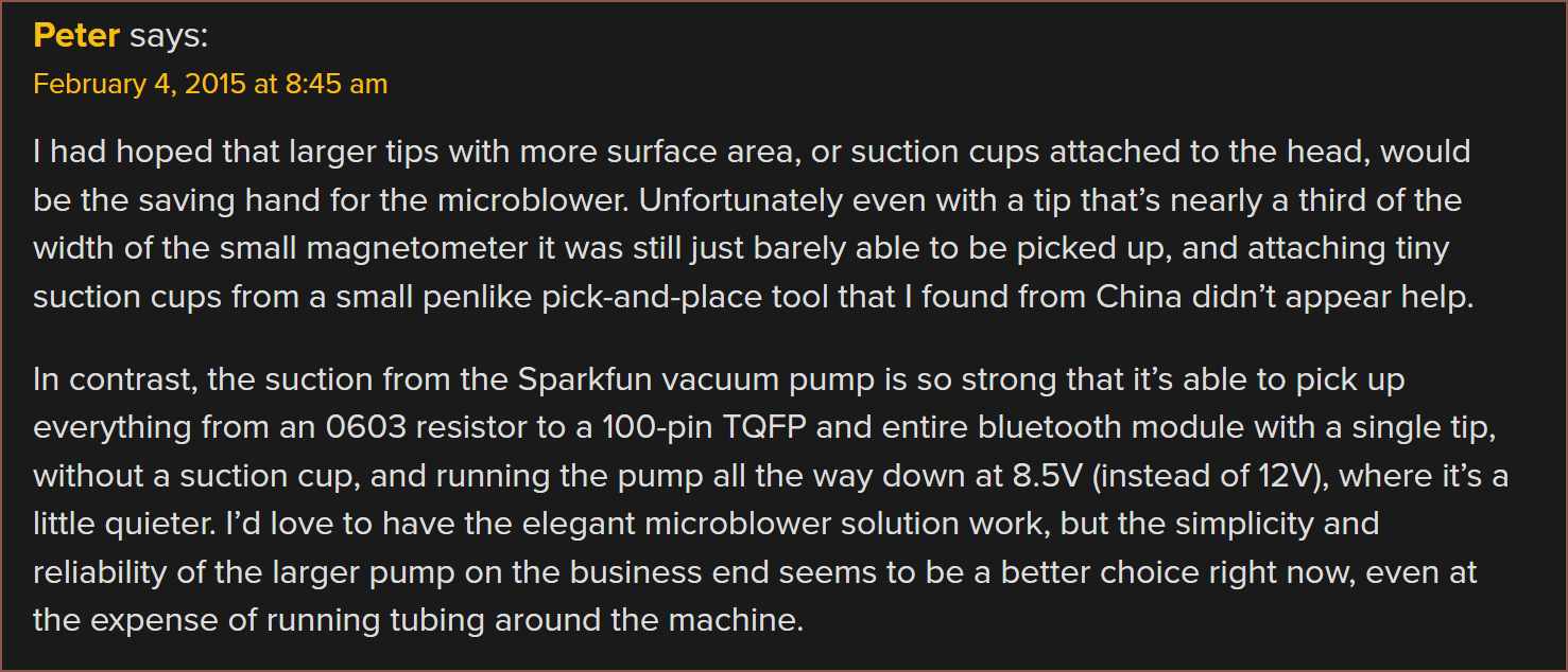
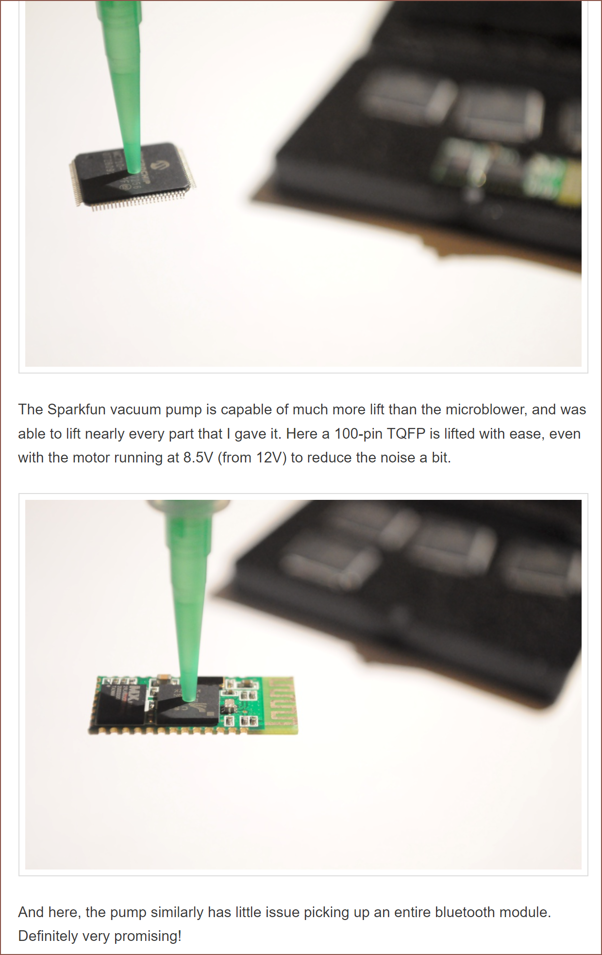
Anyway, I've realised that I don't need to limit the Z height of the paste/fibre head to the same height as the roller, since as long as it's under around 65mm in Y, it can be fully moved out of the way. Thus, I'm researching PnP grabbers to see if I can fit it in the head and eliminate the arm entirely. I was worried about having to have multiple nozzle for different sized components, but as you can see from that hackaday commentor's experiment above, it's likely a non issue.
Researching silver paste
I also need to decide how heat would be applied to the components and silver paste. I might have to find a room/low temperature silver paste. Doing some light research suggests that the question of solder paste vs silver paste adhesive has been asked before.
This gives the impression that it's possible to not need the former and that the components would stay on the substrate well enough to be moved into a curing oven (in my case, probably a food dryer or a heated 3D printer bed with a bowl on it).
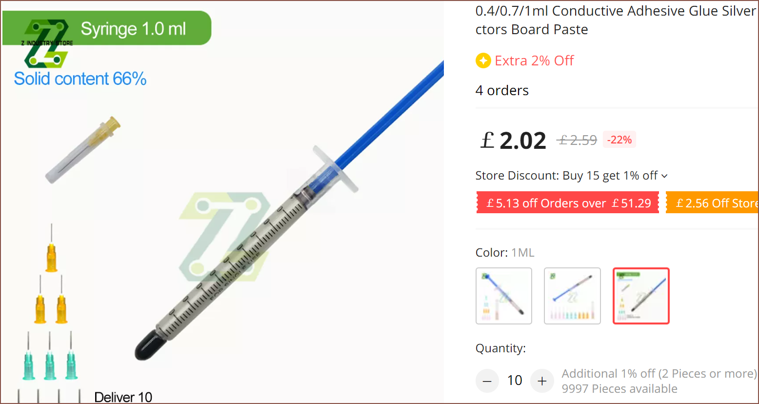
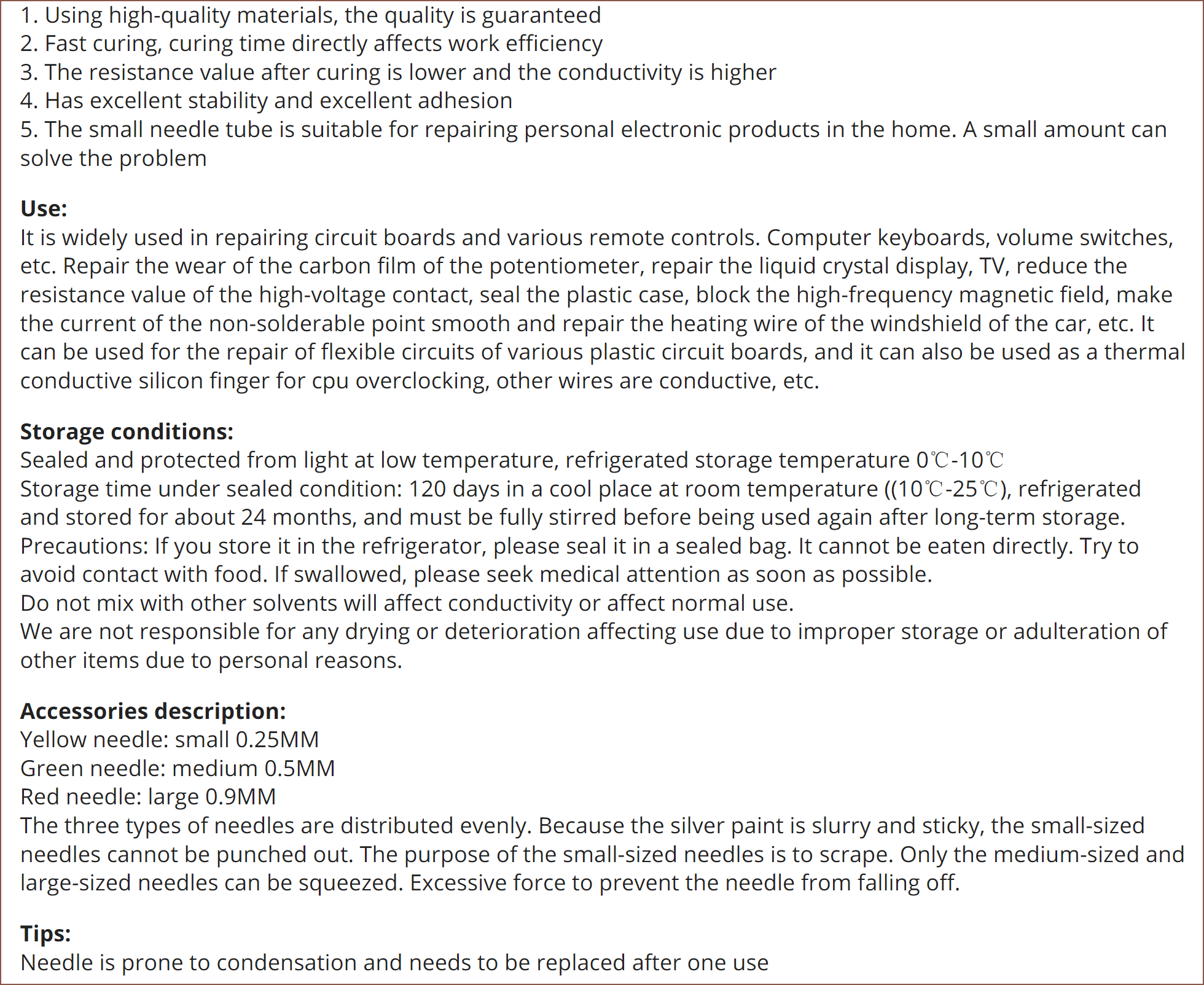
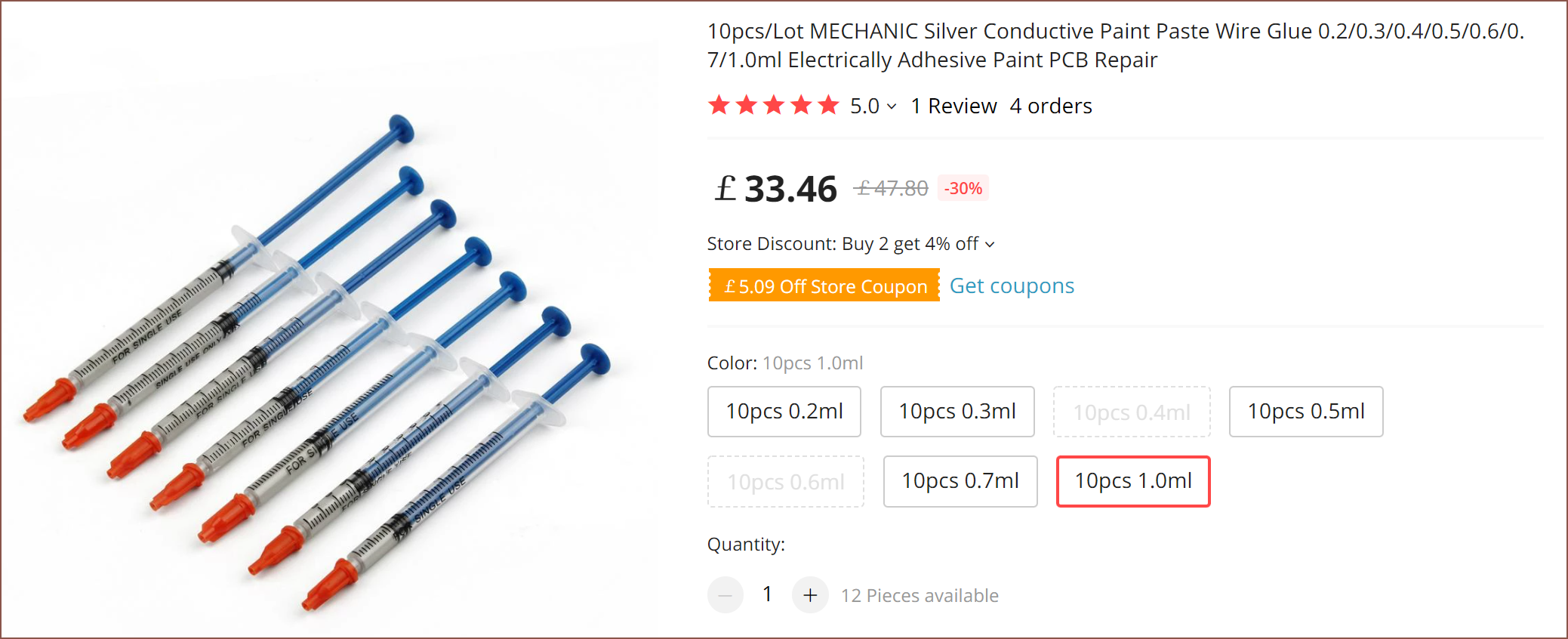
Oh. It's that easy. Wow! But doing more looking, it seems that AliExpress sellers don't just sell the same generic noname paste like I originally thought so I should look around.Hold up it's only £6 delivery for 10ml @ £2 each. That's like £3.12/ml after tax -- way under the £4.50 I estimated the PCB cost with. The description also has a wealth of information:So this one has a potlife limitation and apparently can't be extruded through a 250um nozzle. I wonder what ECA the researchers used as they were able to get track widths of 134um, so I was aiming for a 100um nozzle for 120um traces.The multimeter is on the 200 ohm setting, so I believe they missed a "." in the caption. Still, 5.5 ohms for a track of that width seems kind of high. Nice to see that it'll work fine on flexible PCBs.This answers the question I had earlier up in the log.
Back to the research paper, they used a 250um nozzle and I didn't see the "and height" part of the below sentence:
EJ4110 has <=20um particles while EJ2189 has <=45um, so I was like "yeah that makes sense how the line width of one is slightly over 2x the other. Any line widths over 200um is a no-go-zone, so I'm thinking of going with a 150um nozzle and finding a less viscous silver paste so that I can hopefully get 160um line widths and 40um layer heights.Left:EJ2189, right:EJ4110
https://unimtech.com/pastes-for-printed-circuit-boards/ has pastes that can go as low as 50um line width and >150mm/s print speeds with a viscosities of <350 cP and particle sizes of <8um. The issue is the high cure temperatures and no indication of price, so it's probably £££.
Concluding thoughts
It seems that implementation complexity is something that I'd have to visit at a later date, since I'd need equipment to conduct my own tests. For now, I've got a general idea of the system, so I can make a concept placeholder for the design. Due to favouring probability-of-success and wire management over saving a £ here or there, I'm going back to the M8P + Monster8V2.
Due to the fact that this printer is targetting the consumer and light prosumer, I'm expecting that most components won't be bought in enough quantities to come on a reel. The PnP would pick the components from trays similar in size to the PnP wheel.
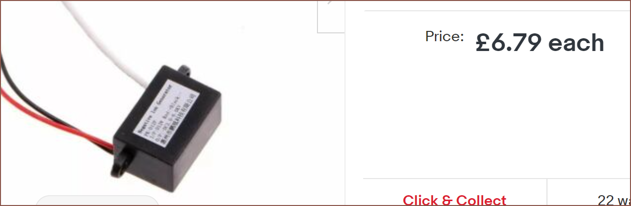
This means that I can use the negative ion generator modules I found across Ebay and AliExpress.
I wanted to calculate how much electromotive force (aka voltage) I'd need to wrip-n-tear excess resin (aka finding the force exerted on a molecule of resin and seeing if it's greater than the surface tension) but it's seems that it gets really mathematically intense really quickly. Thus I've just gone for the -2 - -6KV version over the -0.5 - -3.5KV generator. The other potential problem is that the LCD is within a few centimetres away from the charged plate, so I'd rather not have a higher voltage than necessary. Speaking of the charged plate, I'm wondering if turning it on whilst the resin is laminated onto the film would increase uniformity as if by negative gravity.
https://patents.google.com/patent/CN101659785A/en Now this sounds like a patent for me. Wow, environmentally friendly, nontoxic, based on water and alcohol (aka ethanol most likely) so this run could actually work.
At the modelling rate I'm going at, and with other projects I still have to tend to, it's not looking like I'd be able to receive parts and start building until the second half of September, so I'm slightly sadly scrolling through Youtube, seeing what could be printable with the Suspense. I actually wanted to have a design ready and start ordering parts on Aug 1, so I'm at least 3 weeks behind that goal.
I'm noticing that there's a few things that could use some integrated conductive traces.
With the supreme conductivity of silver paste and my research suggesting that its use would be affordable, I'm thinking that coils could be back on the menu.
With things like the PnP wheel (video below), and the fact that products from Voltera and Nano Dimension exist without PnP functionality, it seems that 0 to being able to 3D print PCBs is a more valuable jump than 3DPCB's to auto populated 3DPCBs.
The roller assembly is no longer needed, but that really just leaves a void of space that could be better utilised with the silver paste extruder. I'm also thinking that it would be possible to fit the fibre applicator on there too instead of on a scara-like arm.
The first benefit is that conductive and fibre paths can be placed in the print up to around the build height back when I was using a roller. The second one is that I'm much more likely to be able to pull of 120 or even 80um silver tracks with a cartesian motion system as no angles are involved in positioning.
Then there's the fact that it's more space efficient, meaning that the SecSavr SuspenseSmall could have this installed. Additionally, moving the fibre tool onto the gantry would increase the amount of space for the PnP tool if it ever comes to fruition.
Speaking of which, it should still be possible to implement my magnet stacking reusable supports with the degaussing electromagnets I was going to use in #SecSavr Sublime [gd0036], and I'd like to see if it's possible to implement placing SMD resistors and capacitors since they're symmetrical in 2 spacial planes. It would use the same motor as the fibre tool.
The kinematics to be used is CoreXY. Hopefully I can fit all that and the unsupported MGN9 rail in a 60x102mm footprint, but it's probably going to be twice as long. Oh and I might add a screen on the front for some visual flair. I'm thinking that this is going to add around £50+ back onto the BOM, but I think it's well worth it.
I'm going to refine this, but this is what I came up with.
Originally, when I thought about using servos, I planned to use 2 -- one for each arm. However, once I got to thinking about the torque requirements for keeping the LCD down and problematic powered-from-off states the arms could be in, resulting in component damage, I wanted to revisit the idea of using 1 motor for both.
The idea I had going into it was some kind of incomplete gear solution.
I was worried about the modelling complexity (and that's the reason why I had the servo idea instead of using a stepper), and I didn't like the idea of relying on magnets to keep the panels up when the drive gear wasn't in contact with the driven gear of said panel. Additionally, I may need a high torque motor to prevent the LCD panel being pushed back up.
Whilst scrolling though all 507 mechanical movements on the site, I had the idea to use a groove track, like:I'm not sure how much friction these kinds of things have, so I've just used a 5x14x5 bearing in the design for now. It is very most likely going to be replaced by an 8mm smooth rod/steel dowel.
Movement explained
The track has 2mm long horizontal sections after a movement for lower tolerance requirements of the servo. Additonally, I'm thinking of moving the servo somewhat slowly (180 degrees per second) to cut on noise.
This configuration starts with the LCD panel all the way down on the surface of the film and the Charge panel at 45 degrees. As you can see from the Charge panel will almost completely cover the expected light path of the UV lamp.
Leftwards movement of the groove track from 0 - 10.18mm will slowly move the Charge panel until it is parallel with the expected light path and thus completely out of the way. The LCD panel hasn't moved. This is to control how much of the screen is exposed to UV light in an effort to increase longevity when only part of the screen is needed to expose a part of the layer.
The next 9.62mm of movement will (relatively quickly) move the LCD panel so that it is also parallel to the expected light path on the other side. Now the configuration is in a position to cure the layer.
Moving the track another 12.8mm will move the Charge panel down against the film. As you can see by the horizontal move in this part of the track, any force that attempts to push the panel up will be counteracted by the force exerted on the bearing pushing on the side of the track. This is the same for the LCD panel, thus the holding force of the panels are not dependent on the torque of the motor.
I've typed up all the tasks I could remember from the computation to get me from my current point in Fusion 360 to the modelling finish line, but not in order:
The last time I did this was the #SecSavr Skyrise [gd0092] and I had a full Fusion 360 model in 3 days. I don't know if I'd be able to do the Suspense in the same kind of time, but it means that I'm at a point where I've got confidence in what I need to model.
This to-do list hasn't dealt with the specific implementation of the fibre applier or PnP head.
I've also been cleaning the BOM file, and I'm at 26 motors total. A few weeks ago, I was expecting 26 motors for the Suspense alone, but now it's 26 for both systems. The current incomplete BOM price is looking pretty favourable now.
£649 for the SuspenseSmall looks to be in the cards, and I might have a shot at £599.
The only issue I know about is that BTT has said that their CB1 can only do 4096x2160px instead of the 4096x2560px the screen has. I can't find anything saying that the CM4 can do any better. HDMI 2.0 is on both, and places like wikipedia say that it should be possible for 5K@30fps, so I'm just going to buy it and try it. I only need something like 10Hz refresh. Since I get the full Y axis length of pixels, the solution would just be less efficient when limited to 84.3% of the LCD, and the X axis may be reduced by 16mm.
A compute that has failed has been the desire to have a resin cartridge that can be sealed-like-a-bottle. This is because it wouldn't be possible to pump in collected resin into the cartridge tank without a way for the air to escape. I think I have a solution which would also eliminate the application pump--
My mental compute as I'm writing this log:
The compute... fails, due to the following confliction:
- The X axis will not move a sufficient amount (>3mm) to
  be able to change the state of the proposed spring
  loaded seal
A new compute is being processed...
A compute... succeeds.
Ok, as I was saying. I have a solution which eliminates the application pump, resulting in the reclaimation pump doing everything. This reduces the moving parts on the cartridges and the amount of motors needed. I'll explain again once I have a concept modelled, but for now I'm going to have to describe it via text.
Instead of my original idea to have both the reclaimation -> tank and tank -> application ports on the bottom of the tank, the reclaimation -> tank silicone tube port will be at the top of the tank and trickle in as seen on the self filling vats that are appearing on printers these days. This is to prevent noise and bubbles.
Source: Elegoo
The silicone tube length between the application silicone tube port and the new application minivat (explained further below) will be long enough that the volume in the tube exceeds the volume pumped into the tank when the layer is reclaimed from the film. This is so that the resin can be retracted to milimetres before the application port before reclaimation (the air would exit through the reclaimation port) and by the time all the resin has been reclaimed, the resin in the application tube would be pushed to the application minivat.
There are two "minivat's" in the design. The first one serves as a buffer for the reclaimed resin to reduce the amount of air that is pumped into the cartridge tank. The second one I've thought of now is the application minivat, which is something more like a waterfall tap.
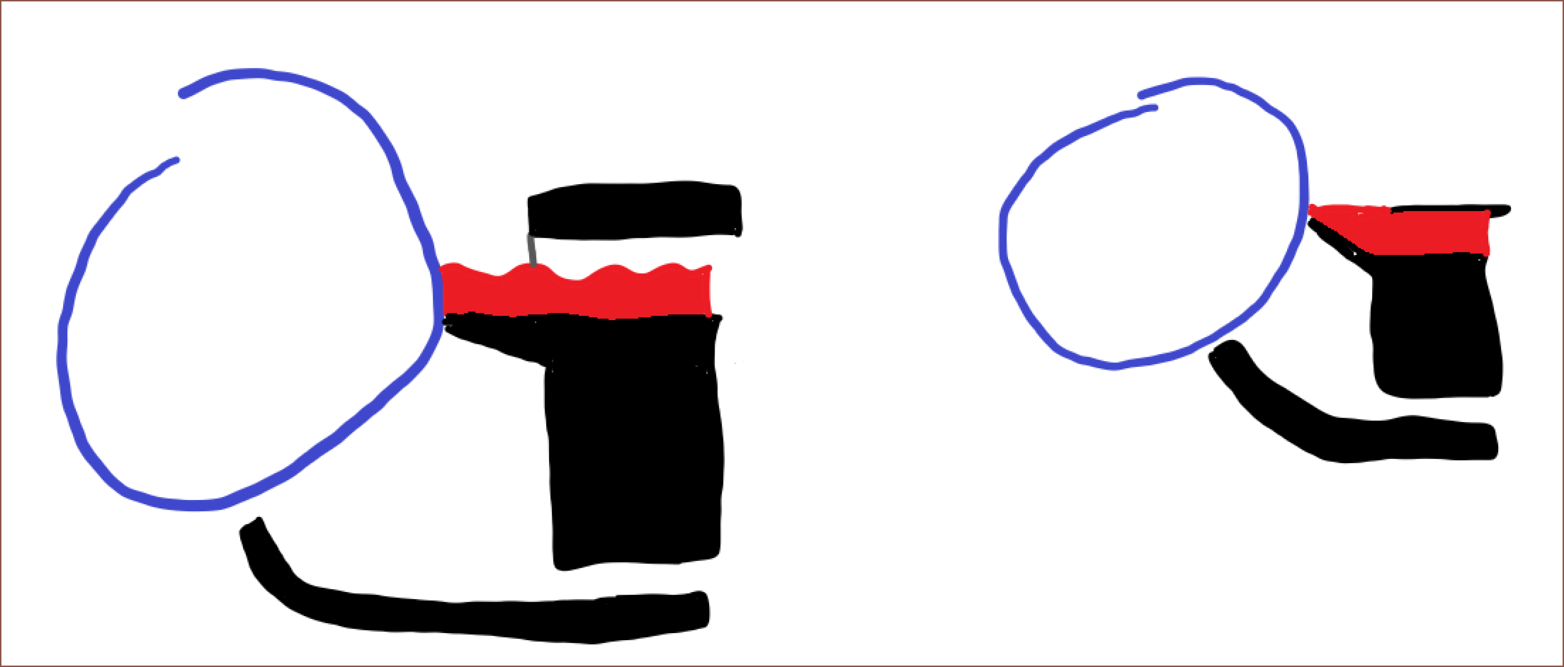
Source: Appliance DirectThe minivat is integrated with the application knife and is sloped such that gravity pulls unapplied resin back into the minivat instead of sitting ontop of the knife. Here's a quick doodle of the before on the left and after on the right.These changes reduce the amount of steppers to 9, but since that's just 1 more than the M8P and the X axis strategy I'm doing prevents me from applying from one side while reclaiming from the other, I'm replacing the £10 EXP MOT + cables with a £2.70 2 channel relay that connects to the 2 pump motors. These motors are actually the only ones that won't need constant power, so is the most fit for this purpose.
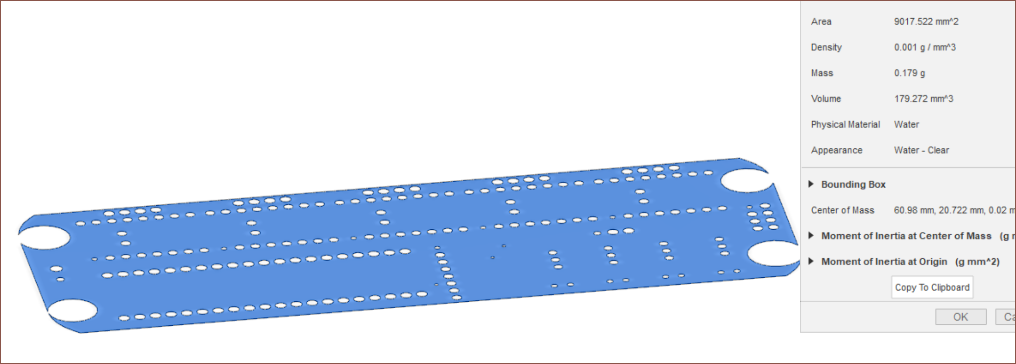
I've been meaning to find out how much conductive silver paste is actually needed for a PCB. I used an old gerber file for a #T^2 Tiles [gd0095] board I never got made. Long story short, Fusion 360 kept crashing when using the svg (converted to dxf), so I just went with a simplified dxf.
I've used water to get the volume, which would be 0.18ml. Multiply this by 2, and it's 0.36ml for a 2 layer board with conductive planes. For the resin minus the 80 microns for the conductive layers, the volume is 7.05ml.
Looking across the internet, it seems that the going rate is £4/ml and up (incl 20% tax).
Then, even with this first-seen-in-industry, as-non-toxic-as-PLA-in-liquid-form resin I found out about yesterday that costs £78 after tax for 500ml, I'm only looking at £1.0998 in material. I'd like to believe that some high temp resin or "digital soldermask" resin would cost less than this.
Assuming the conductive paste is £4.50/ml, the final price is £1.10 + £1.62 = £2.72 for a 122x42mm (5124mm^2) board, which is actually in my league budget. The square area is 51% the size of the 100x100mm boards for $2 at JLCPCB. I had a second revision, 3993mm^2 board fabricated (which was 110mm on the long side so couldn't get the offer), and the minimum order quantity (MOQ) of 5 cost £8.70 with ultraslow shipping, coming in at £1.74/pcb. Extrapolating the above, a print of this size would cost £2.12 and should arrive wayyyyyy faster than 4 weeks. Likely even faster than next day delivery.
These conductive paste's required quanities and prices per ml mean that it's also not favourable to use the L^3 method. I imaginee that the lowest end minimum fill level for even a silicone-tube-only (no tank, but collector pump straight to application pump) cartridge would be >15ml.
To start of my research, I looked into laser toner viscosity which didn't really find anything viscosity wise, because it turns out toner is a powder and a very fine one at that. There's even magnetic versions, suggesting that it may be better to have magnetic particles in the resin instead of magnets on the printer. As I guessed, the charged and magnetic solution could be combined for dark resins, which should result in even greater cleaning performance.
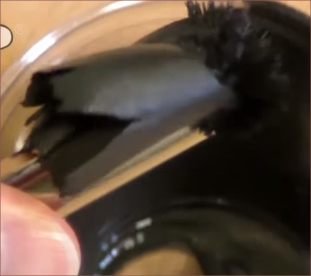
Then I looked into magnetic paints. I found out about erasable crayons and dustless chalk, but then I found this:
Ok... the paint just got rip-n-torn clean off the bottom of the transparent cup. This'll work, 100% no doubt about it.
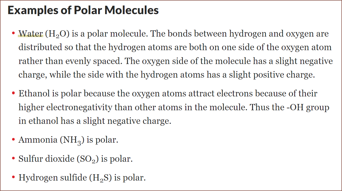
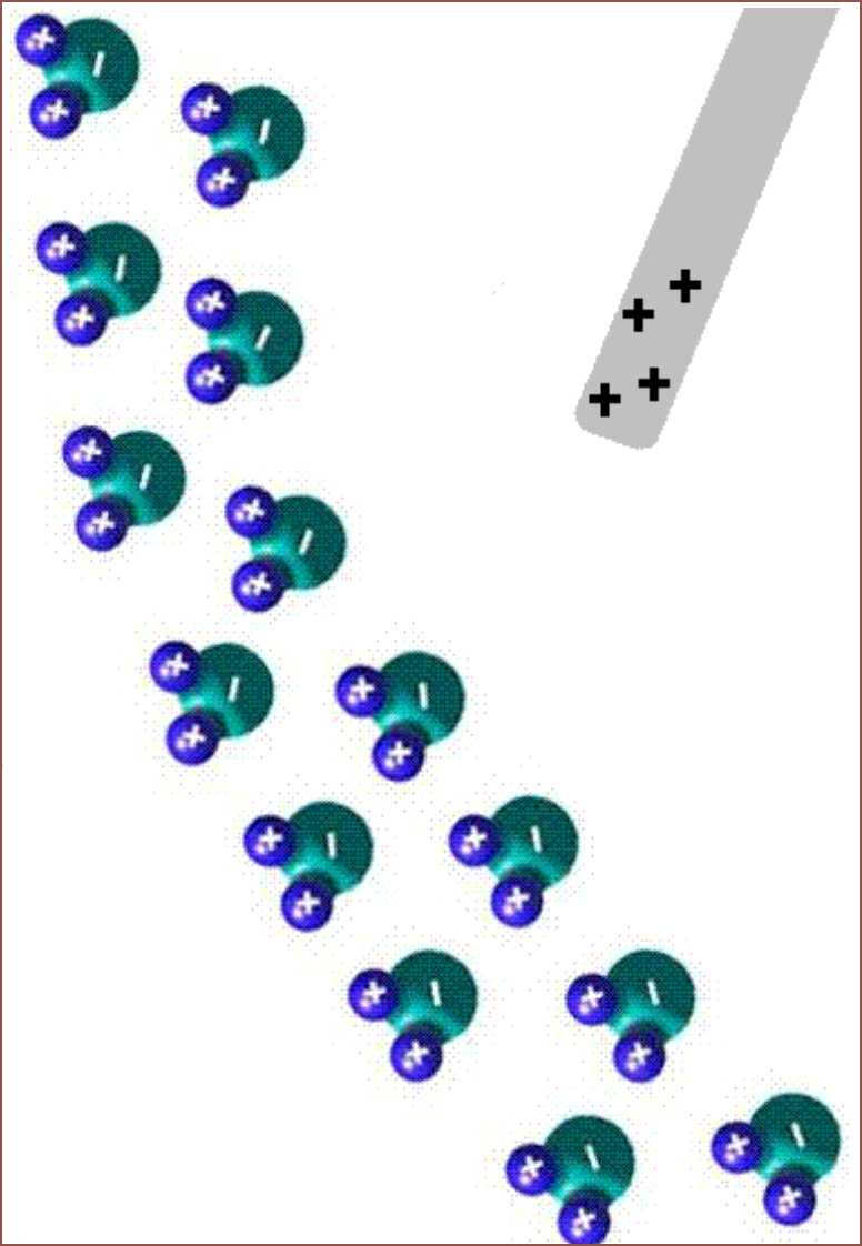
Now that the magnetic solution has been validated, I went back to researching about an electrostatic solution. I found a webpage that explained this school experiment I've long forgotten about involving a water stream and a charged rod:
The page says that polar molecules have a greater effect than regular dust. Speaking of water, it sounds like the relative humidity should be low, but that may only apply to generating static electricity by rubbing. Here's a video I found, and the force seems pretty strong even at a distance magnitudes further away than what I need:
I wouldn't imagine a vacuum being this performant at the same distance.
I also found another one that shows a cheap way to generate the charged plate needed for the printer:
This board can be powered from 3 cell batteries. From reading the comments, I was able to deduce that this one creates negative static charge. The commentor deduced this by seeing that the diode is pointing away from the output.
Conclusions
I can cut the LCD stepper motor (and slightly complex gear arrangement) solution I originally thought of and go with 2 light servo motors that only need 2 pins on the motherboard and no stepper driver controllers, since there isn't any high angle precision required (unlike the Arm Attachment). This reduces the motors needed for the Suspense + Arm Attachment to 19 and, more importantly, the SuspenseSmall to 11! Since 8 steppers are used for the Arm Attachment, they can all be mapped to the Monster8 and the main system can entirely be on the Manta M8P + EXP MOT. My eyes are now set on reducing the cartridge pumps from 2 to 1 per cartridge, and I'll write more in a future project log.
It seems that I'm going to push some of the required development to the chemical team of the project (which is just me some time in the future) and hope for a resin with embedded polar molecules. The attraction from the plate should work fine in small pockets (80um square, but ideally 40um), where mental simulations for trying the same pocket with a vacuum fails. All attracted resin goes back on the same PET film it came from, so the dream of "every single drop (minus probably 50-150ml for the minimum fill line) makes it to the print".
Also, I'm thinking that it might be possible to partially cover the side of the LCD with the charged plate, reducing UV exposure to the LCD and hopefully increasing its usable life. I need to do more research to see if this would work or if the still-exposed section of the screen would still deteriorate at the same rate. My current understanding is similar to silicon wafer yields, in that covering the screen reduces the area on the LCD that could be damaged, thus reducing the probabilty that there would be damage anywhere on the screen.
My mental simulations suggest that the current roller solution would be unreliable, and it's likely the reason why my modelling speed has slowed this week; the roller assembly moves other assemblies around. I'm thinking that the resin may stick to the roller, but there is a probability that some resin is further pushed down along the edge of the part.
The simulation assumes that the top of the exposed area is fully cured, thus the only location for uncured resin is the boundary between solid and liquid parts. It should be possible to roll the X axis over the section to be printed to prevent the resin being compressed between the LCD and another material in the same layer, though this requires 2 applications on the PET. For a single application, it might be possible to move to press on the part, roll off to expose a different part of the layer and then roll back, pushing out the resin.
The simulation is using 0.2mm layers because I want to be able to draft print if possible and the higher the layer height, the harder it is to clean.
Possible solutions
The ideal solution is one that obtains a result similar to a cookie cutout of dough, whereby everything exposed sticks to the part and everything else sticks to the film. Additionally, the LED strip is ommitted, instead making use of the hight powered UV lamp that already exists overhead.
Since the LCD is light, thin, and for this printer, small, it shouldn't be too much of an ask to install it on a trapdoor.
For non-conductive materials, I'm thinking of electrically charged resin and something on the screen-side of the PET attracting the resin. Something like a toner printer maybe?
Wait... things are getting real close to a laser printer now. The differences is that the laser step is ommited and the "fuse" (read: expose) step comes before the transfer (back to the film) step.
For conductive resins, I'm thinking of adding ferrous powder and having magnets on the screen-side of the film. I have a better feeling that this would work (magnetic putty is just an extremely viscous liquid, right), but the bigger question is making affordable and highly conductive resins. I still believe that liquid deposition into channels would be for the best. Silver paste may be expensive, but only a 1 layer (40um) thick trace would need to be deposited and would still exceed conductivity of 2oz copper traces, and the silver is only deposited where it's needed. I don't have to worry about reclaiming excess paste or the metal particles reflecting most of the UV light if it was in a UV curable resin.
Compute conclusions
Both solutions may allow the "every single drop makes it to the print" ideal that BCN3D and those 2021 researchers talked about. It should also be more gentle on small features, since there shouldn't be any contact (and if there is, very lightly).
As the X axis may now be responsible for cleaning and curing, the application rollers may be brought back for speed improvements, but right now I need a minimum viable product not a max velocity printer. Thus, this solution should remove:
4 stepper motors
(so all the cleaning roller related motors and 1 motor is repurposed to move the LCD instead of the cleaning thread)
2 stepper drivers
UV LED strips
Most bearings and pullety from the design, as well as some 2GT belt
The cleaning roller and the hand-cut aluminium channels
Long strands of thread as a consumable, and the associated maintinance downtime
This was one of the things holding up a compute. The problem was being able to get the thread into position and how the thread bowden would get to/leave from the roller assembly.
2 linear rails
Additionally, the Z height is likely to increase by 20mm.
Now I need to research how to negatively charge liquids and what voltages would be needed for the anode.
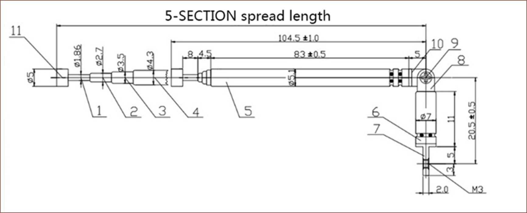
One of the comments in here talked about using telescopic antennas. Looking at build plates for SLA, especially top-down designs, it seems that resin prints can tolerate gaps, so I looked into a full-bed solution. Telescopic antennas would allow a finer height adjustment than stacking magnets (and magnetic cylinders of the same size and thickness in an alternating pattern so that the stacks don't push each other apart).
I found some 27p/each antennas that extend up to 37cm, though in practice with many antennas, I expect the safe height to be 36cm. The end cap looks similar to the face of a magnet and flat enough to print on.
However, that's not an OK price. Apparently, the system in the hackaday article was or is estimated to be $10K, so that's a 10x reduction, but it would need another 10-20x reduction to be financially feasible. If I assume that I can go with a 10mm distance, the price drops to £239.
For this concept to work, I think it would have to be 3D printed in order to get that kind of precision but cut out labour and shipping costs. In terms of material usage, it's a fair assumption to assume that almost all the volume needed for this bed would use resin. Thus, for 10mm square size and print dimensions of 520x170x100, 8.84 litres of resin would be needed. For a reasonable price, that would require £4/L resin. In my opinion, that would be a nice price for the stuff anyway since I've lived the lifestyle of £5/kg PLA filament. The factory delivered 11kg of the 20kg I ordered for £55. 1kg of filament is 1.3kg of weight including the spool and box, so a shipping charge for a 14.3kg delivery was also built into that price.
If conductive traces could ever be printed cheaply, it could even mean that each telescopic pole can become a linear actuator like this.
 kelvinA
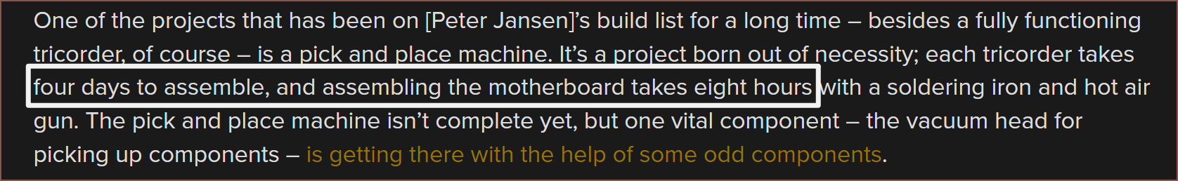
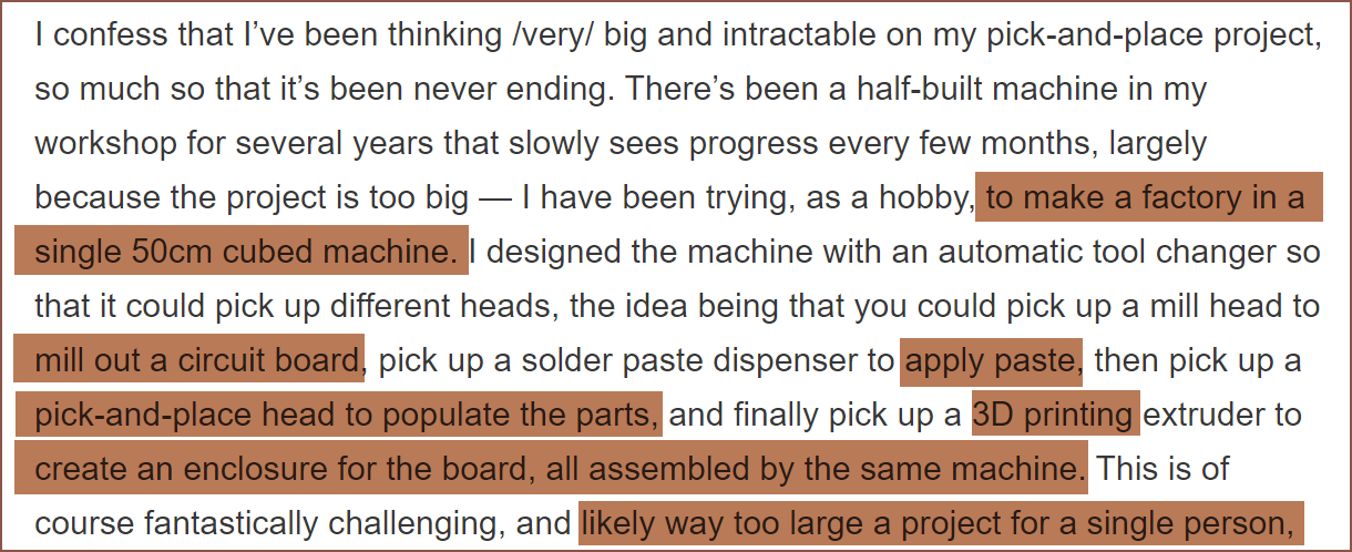 Me, a single person designing the SuspenseSmall in a smaller volume than 125L:
 Wait! This is the hackaday commentor?! Well in this page's comment section, there's someone that sounds like they started FirePick.
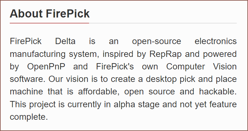 Wait. It's been 7 years since the comment. How is it not even in beta?
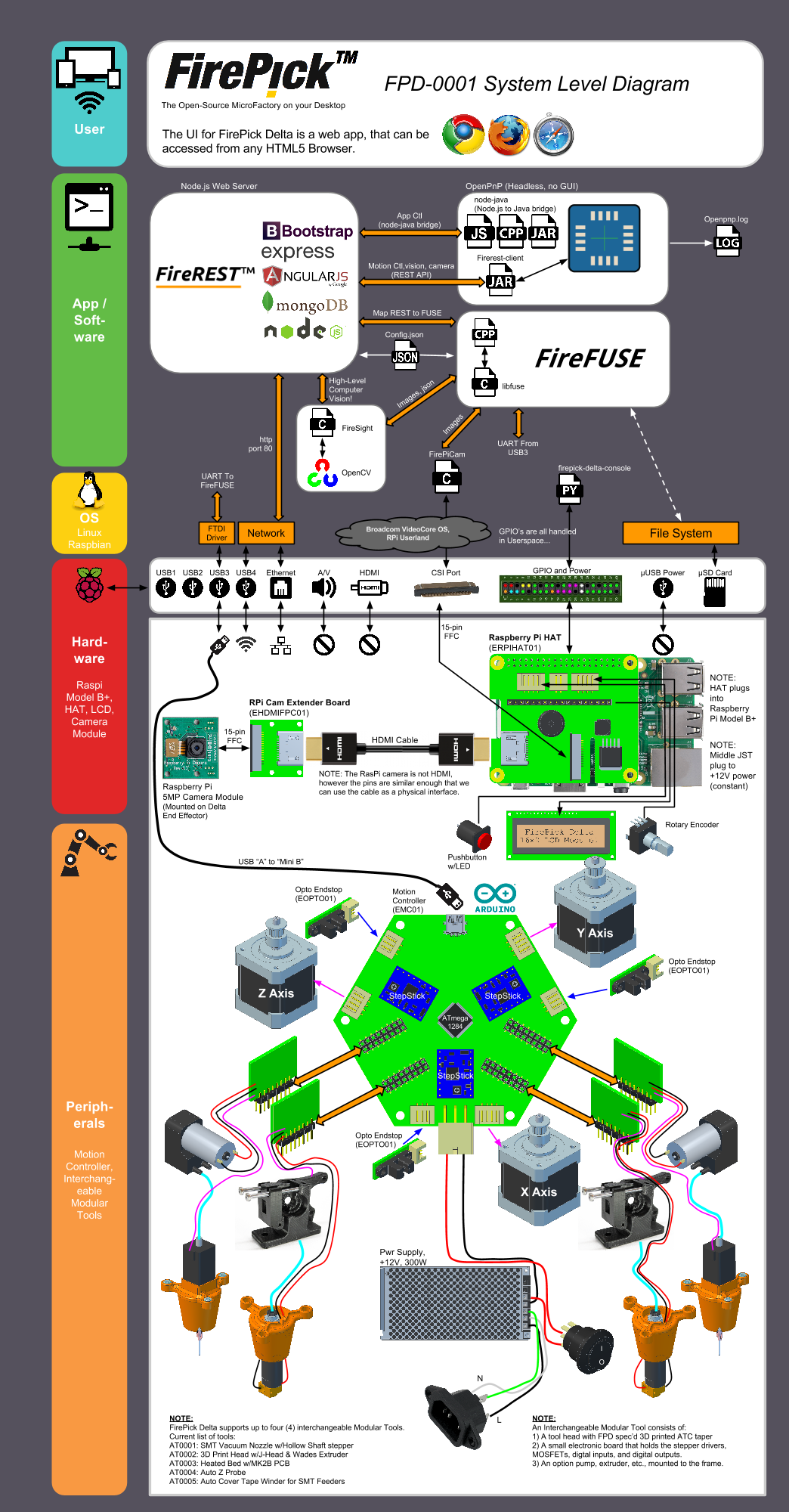 Woah that's actually a lot of stuff.
 Last seen 7 years ago. Oh.
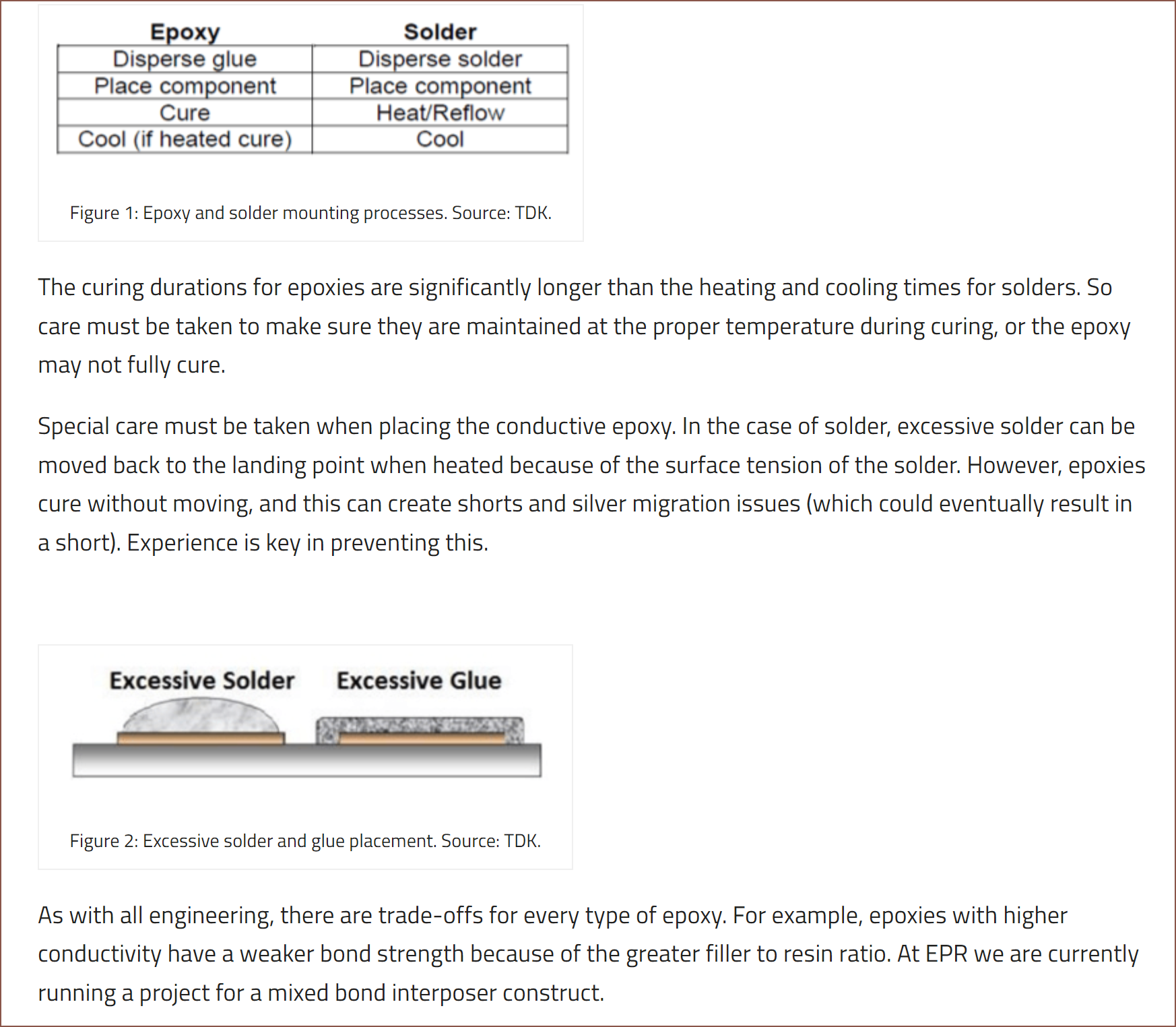

 So this one has a potlife limitation and apparently can't be extruded through a 250um nozzle. I wonder what ECA
 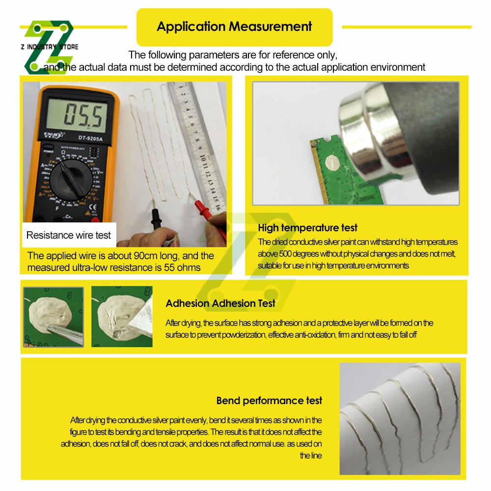 The multimeter is on the 200 ohm setting, so I believe they missed a "." in the caption. Still, 5.5 ohms for a track of that width seems kind of high. Nice to see that it'll work fine on flexible PCBs.
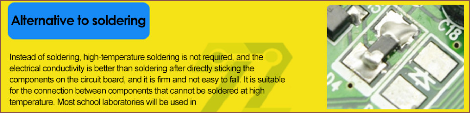 This answers the question I had earlier up in the log.
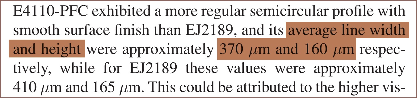 EJ4110 has <=20um particles while EJ2189 has <=45um, so I was like "yeah that makes sense how the line width of one is slightly over 2x the other. Any line widths over 200um is a no-go-zone, so I'm thinking of going with a 150um nozzle and finding a less viscous silver paste so that I can hopefully get 160um line widths and 40um layer heights.

 I wanted to calculate how much electromotive force (aka voltage) I'd need to wrip-n-tear excess resin (aka finding the force exerted on a molecule of resin and seeing if it's greater than the surface tension) but it's seems that it gets really mathematically intense really quickly. Thus I've just gone for the -2 - -6KV version over the -0.5 - -3.5KV generator. The other potential problem is that the LCD is within a few centimetres away from the charged plate, so I'd rather not have a higher voltage than necessary. Speaking of the charged plate, I'm wondering if turning it on whilst the resin is laminated onto the film would increase uniformity as if by negative gravity.
 With the supreme conductivity of silver paste and my research suggesting that its use would be affordable, I'm thinking that coils could be back on the menu.
  I'm going to refine this, but this is what I came up with.
  I was worried about the modelling complexity (and that's the reason why I had the servo idea instead of using a stepper), and I didn't like the idea of relying on magnets to keep the panels up when the drive gear wasn't in contact with the driven gear of said panel. Additionally, I may need a high torque motor to prevent the LCD panel being pushed back up.
 I'm not sure how much friction these kinds of things have, so I've just used a 5x14x5 bearing in the design for now. It is very most likely going to be replaced by an 8mm smooth rod/steel dowel.
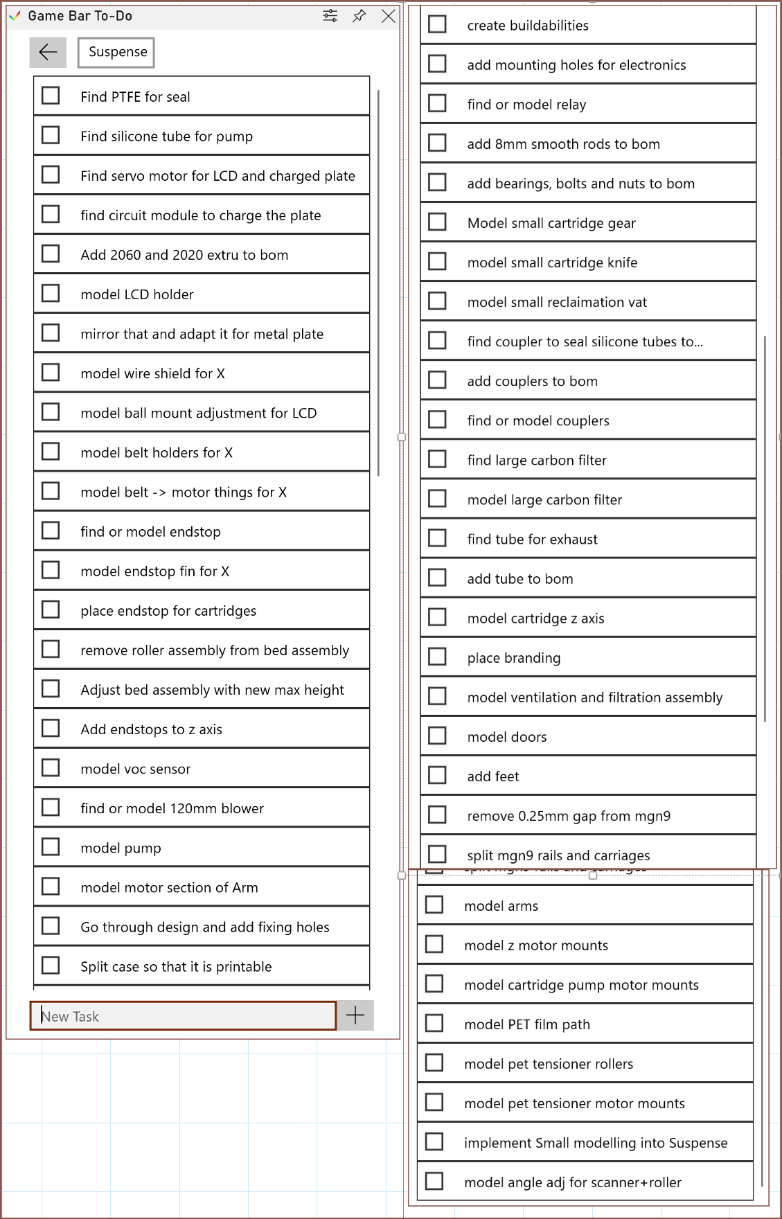 The last time I did this was the
  £649 for the SuspenseSmall looks to be in the cards, and I might have a shot at £599.
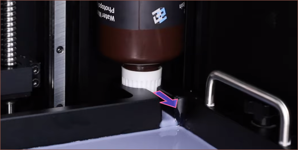

 These changes reduce the amount of steppers to 9, but since that's just 1 more than the M8P and the X axis strategy I'm doing prevents me from applying from one side while reclaiming from the other, I'm replacing the £10 EXP MOT + cables with a £2.70 2 channel relay that connects to the 2 pump motors. These motors are actually the only ones that won't need constant power, so is the most fit for this purpose.
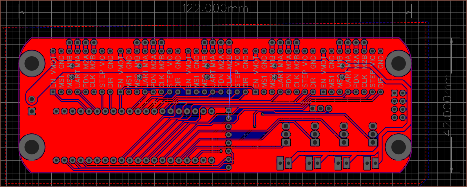
 I've used water to get the volume, which would be 0.18ml. Multiply this by 2, and it's 0.36ml for a 2 layer board with conductive planes. For the resin minus the 80 microns for the conductive layers, the volume is 7.05ml.
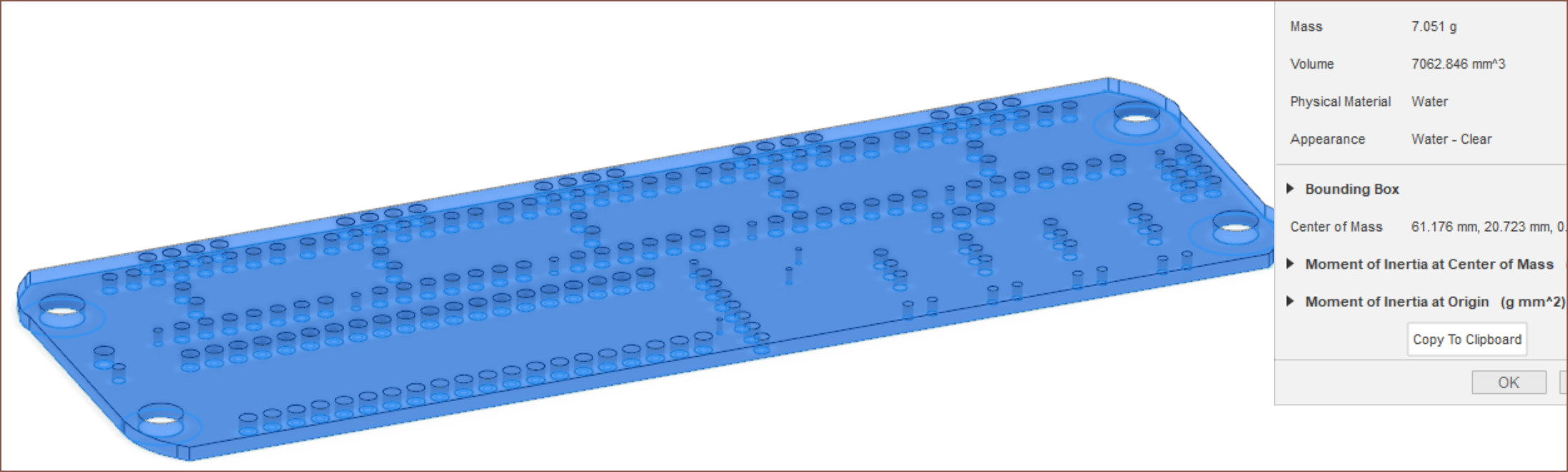
![The steps of xerography [12]. | Download Scientific Diagram](https://www.researchgate.net/publication/269476121/figure/fig3/AS:669991582044186@1536749849632/The-steps-of-xerography-12.jpg)
 Wait... things are getting real close to a laser printer now. The differences is that the laser step is ommited and the "fuse" (read: expose) step comes before the transfer (back to the film) step.
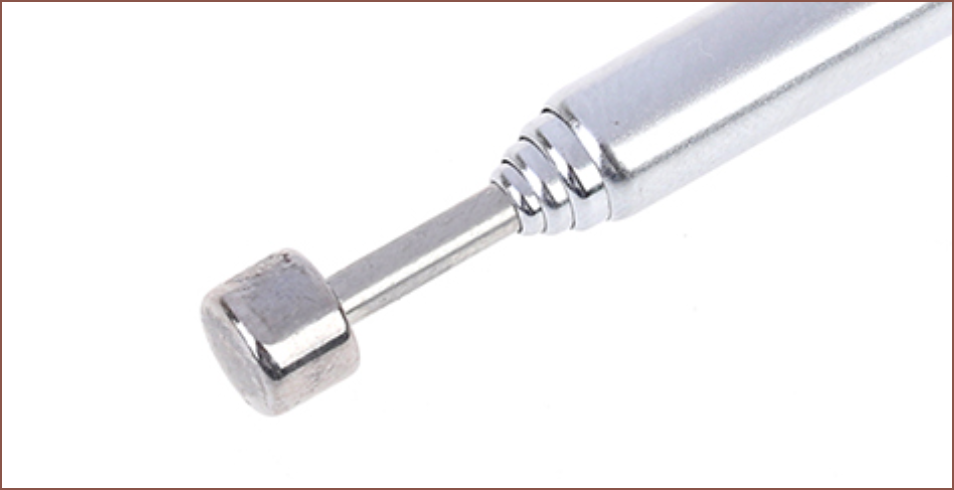 I found some 27p/each antennas that extend up to 37cm, though in practice with many antennas, I expect the safe height to be 36cm. The end cap looks similar to the face of a magnet and flat enough to print on.