 kelvinA
Media
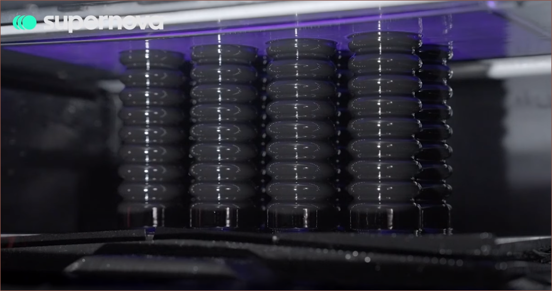
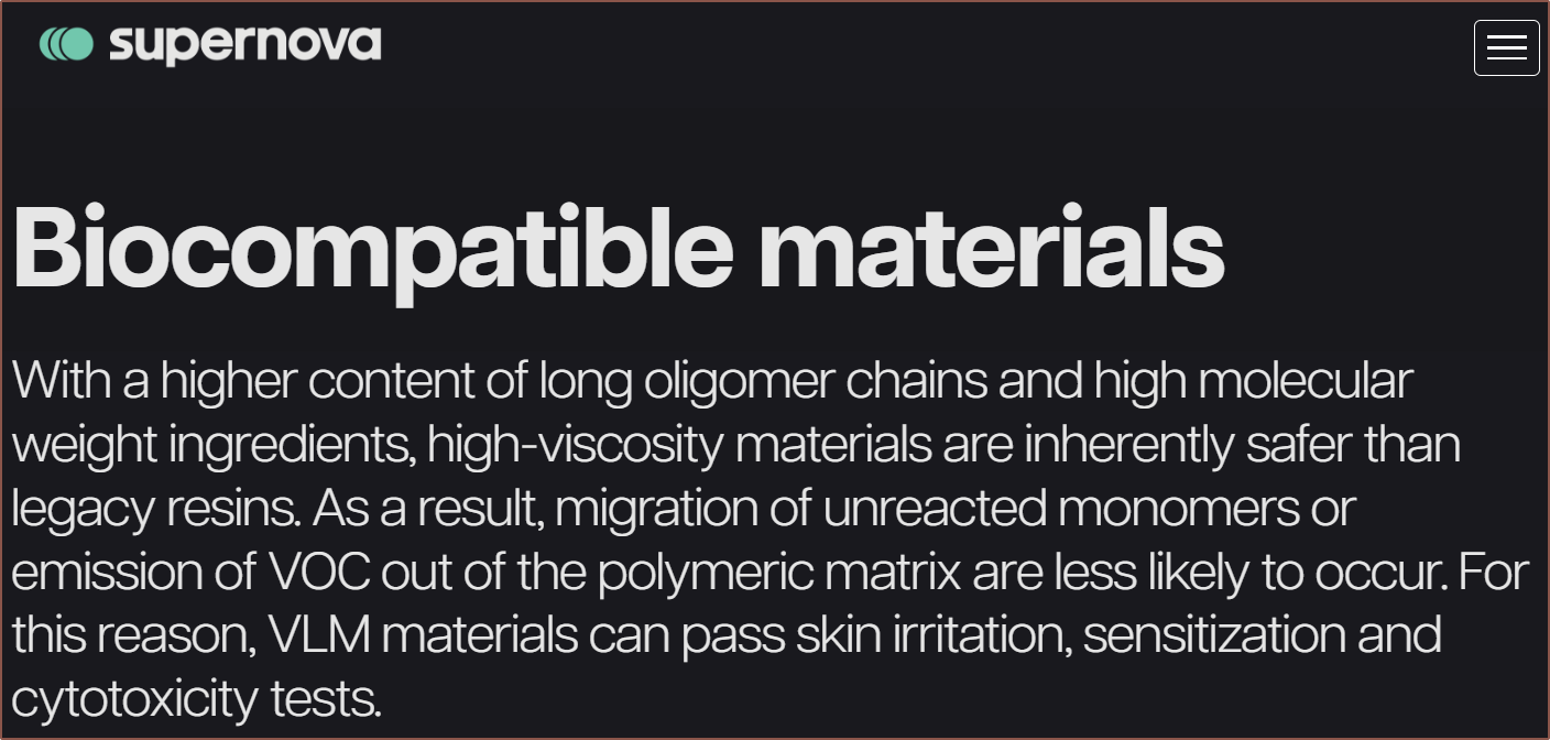
Inspiration and/or examples of working principle
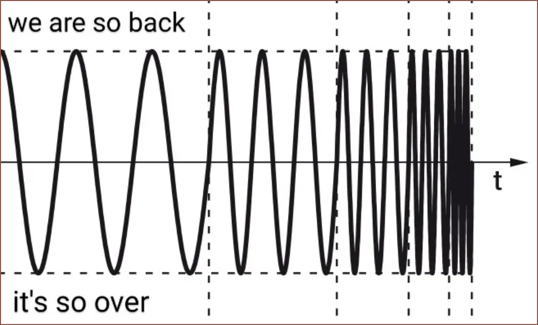
The background music is also the music I mentally associate with this project.
Navigation
The title tag system is explained here, and the most up-to-date is used (so there may be differences compared to the tags actually present in the log's title). Notable logs have bold white text.
Read more »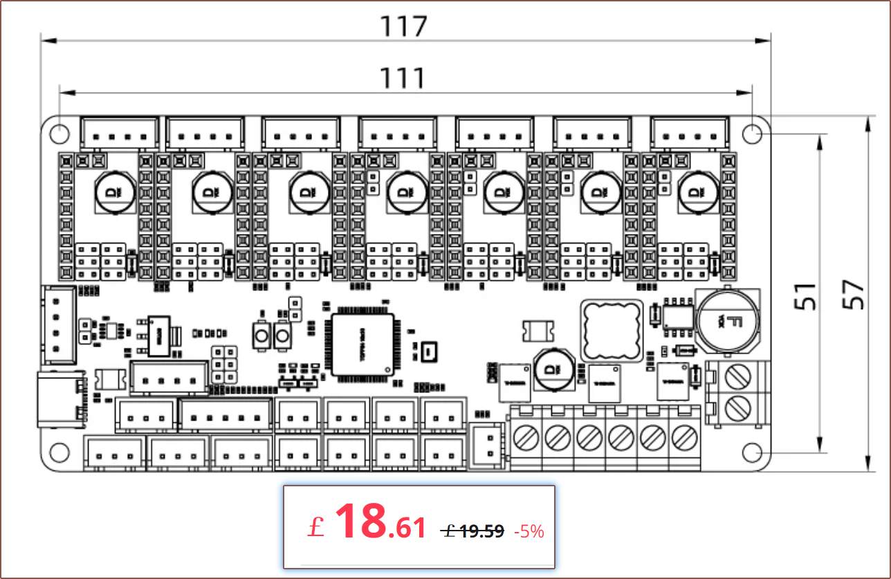
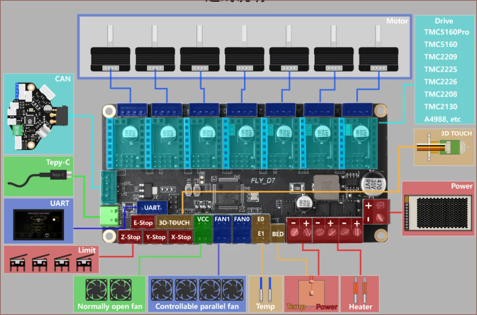
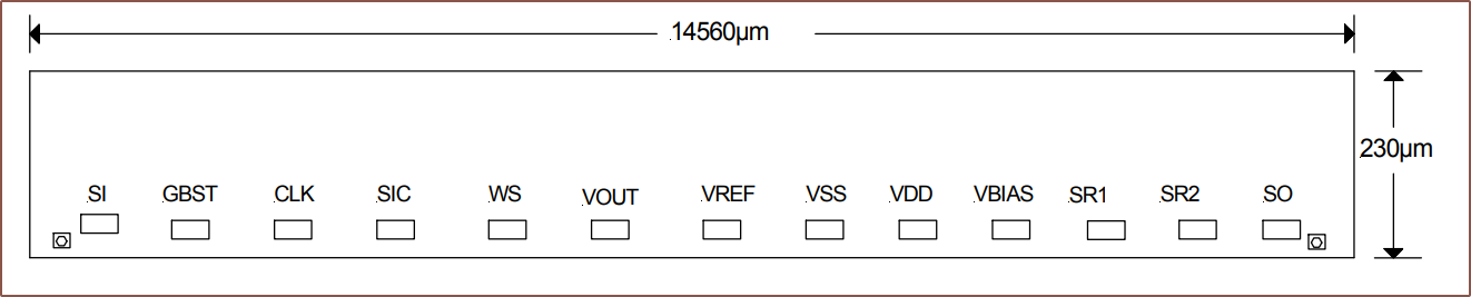
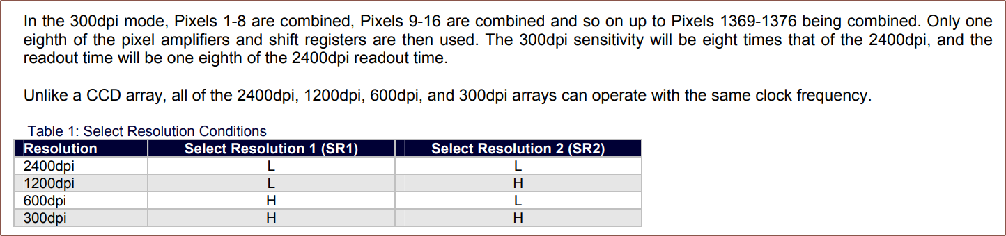
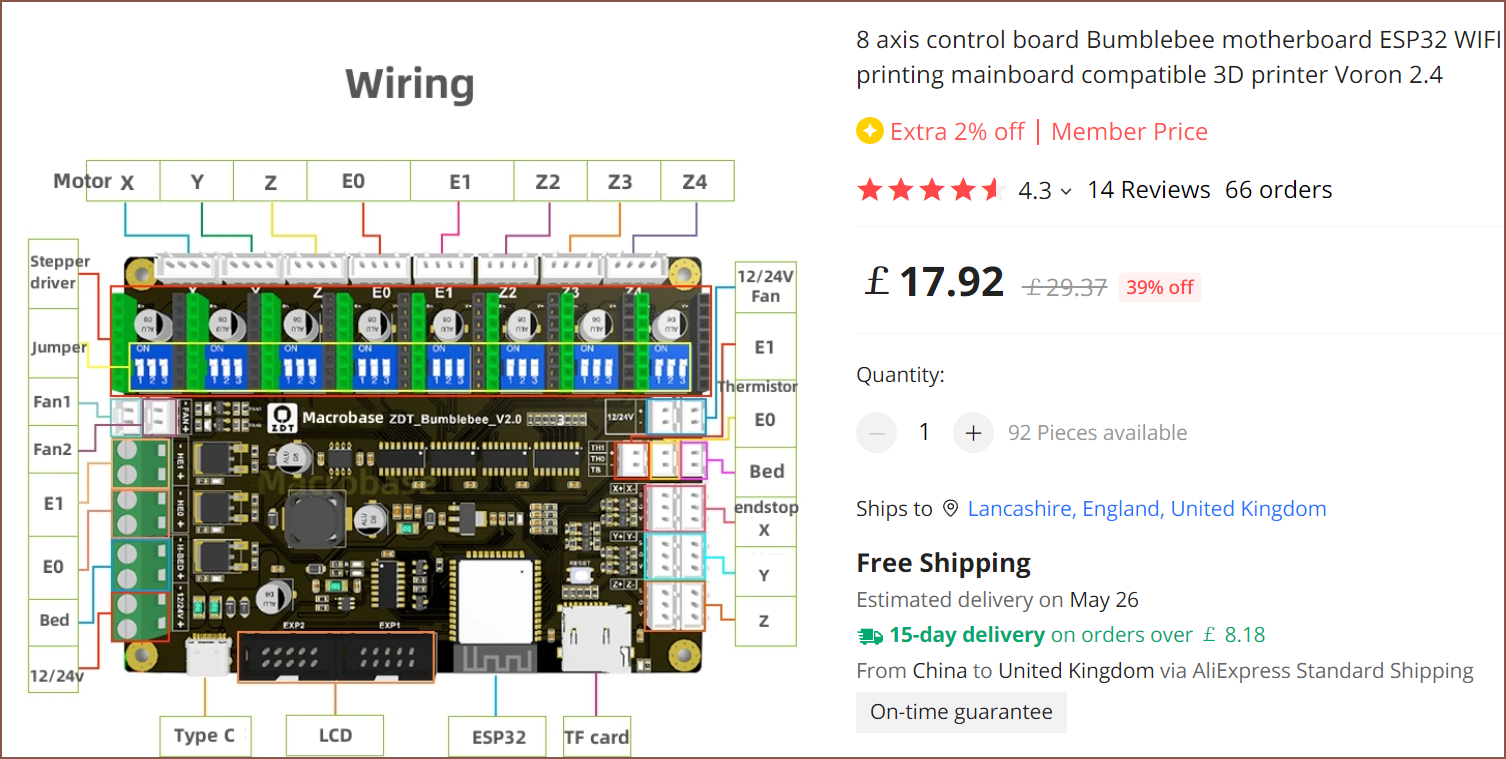
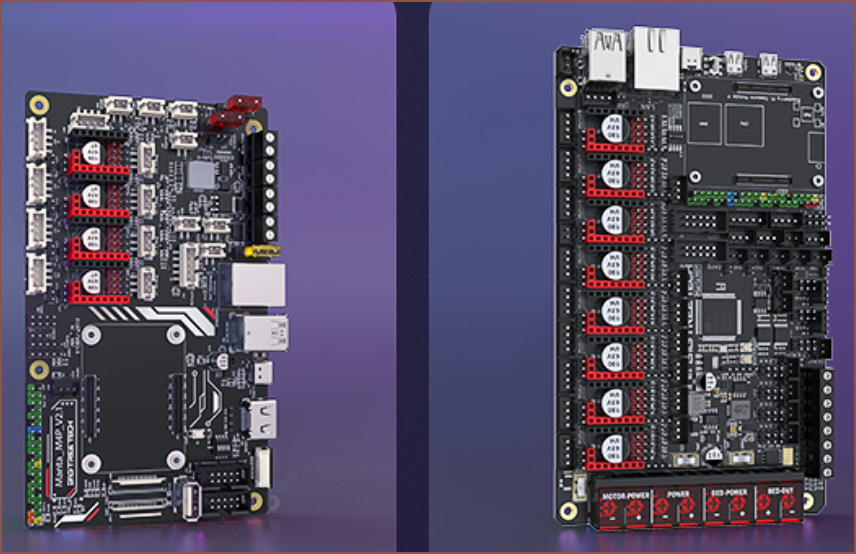
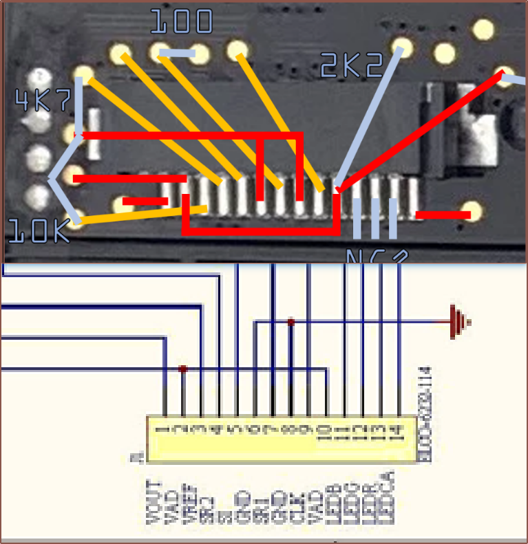 I looked at the pinout here and many of them lined up with the pinouts determined in


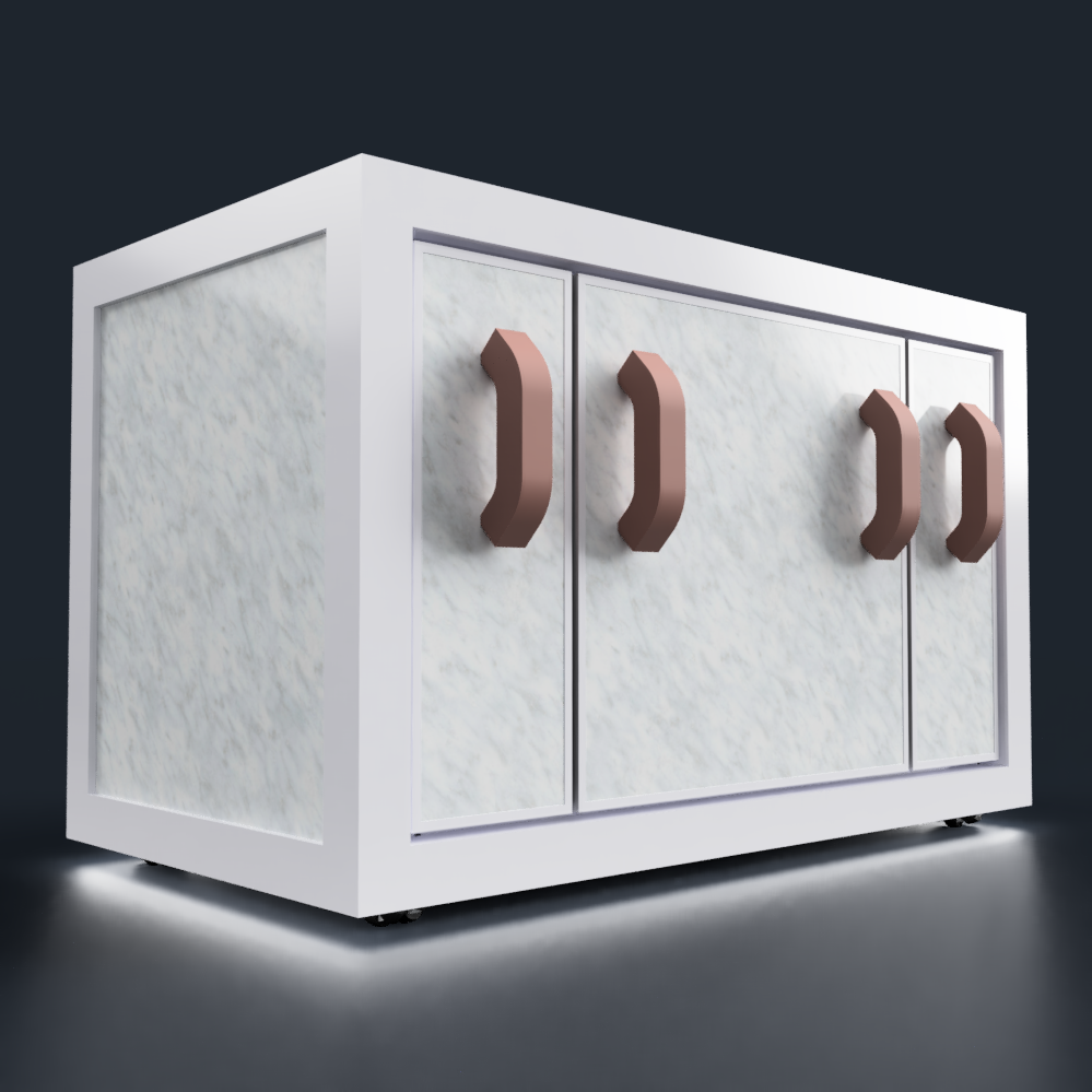
 Remember that interesting looking 3D printers are less likely to be "mass consumer" friendly, even though I doubt any mass consumer would be spending in the ballpark of £1500 (and potentially higher) to print AI generated 3D models.
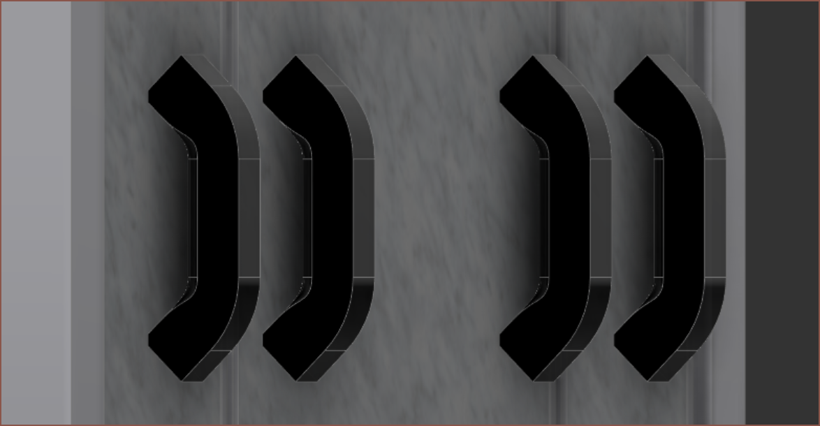 Mn... not sure I like the look of that fillet.
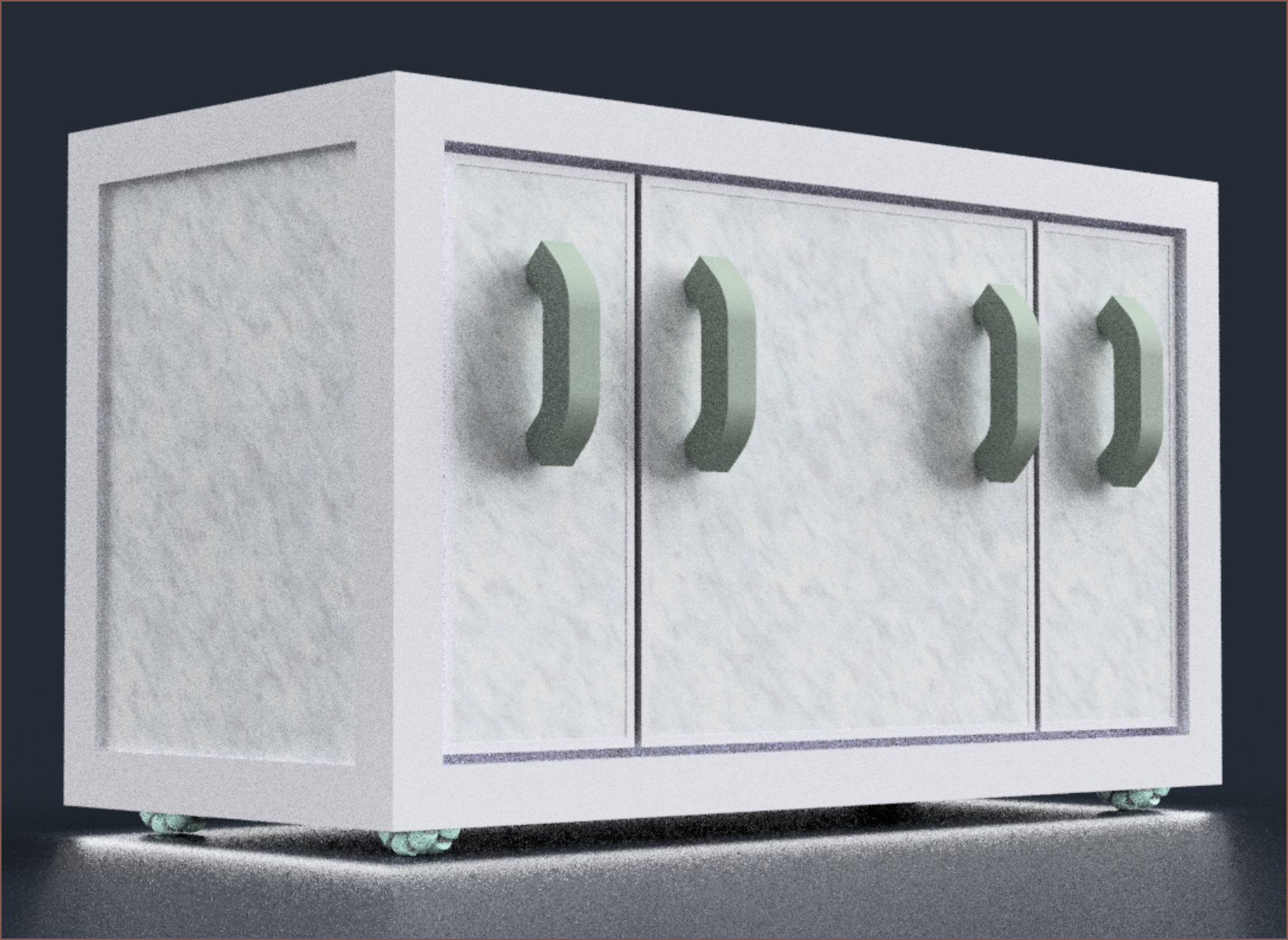
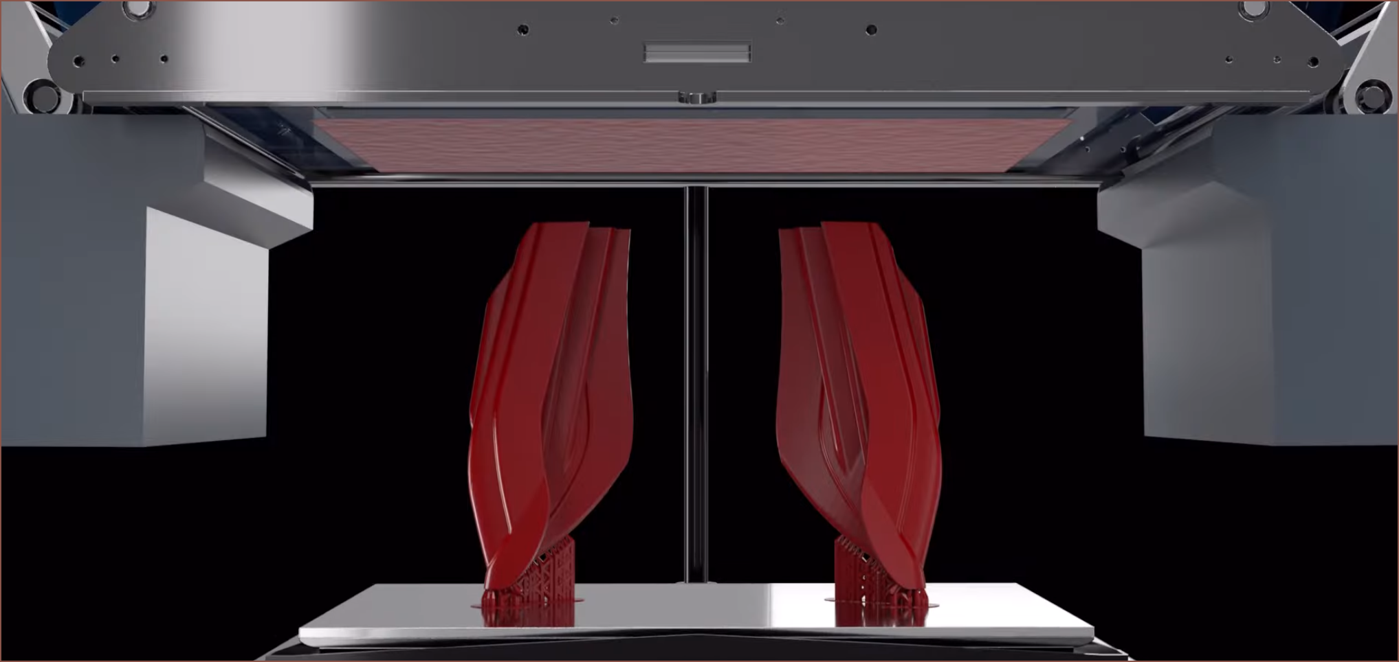
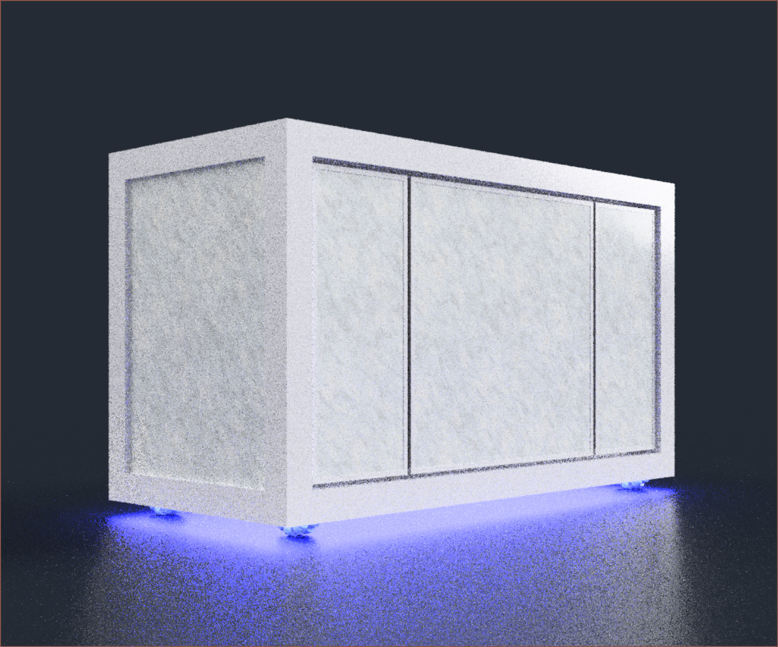
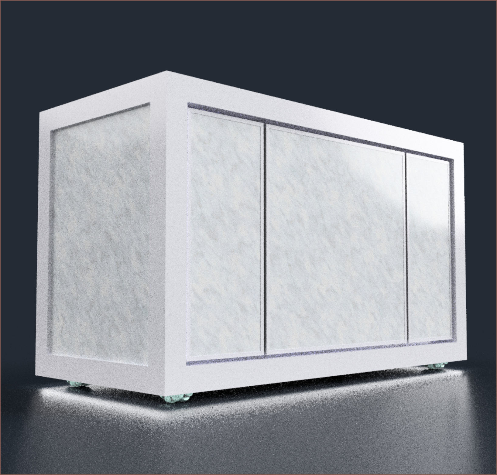
 Wow. This looks SO much more professional and worthy of its £1.5K+ expected BOM pricetag. Print volume aside, you have to realise that my indirect competitors are printers like the RatRig V-Core, Prusa XL, E3D Toolchanger, UltiMaker (if you squint), Raise3D, Voron, Anycubic M3 Max and probably a few others. The printer should look like £2Ks worth of kit.
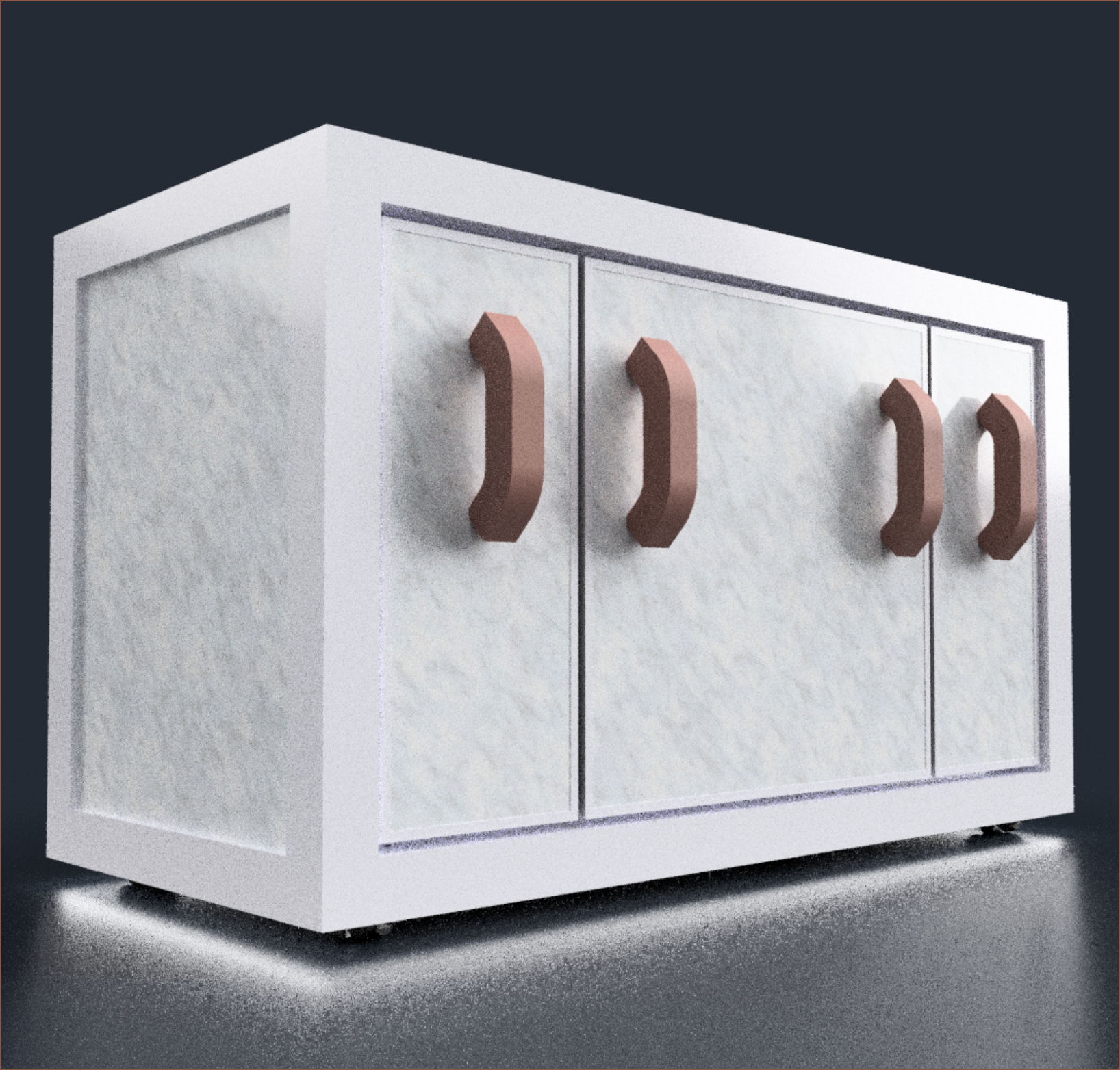
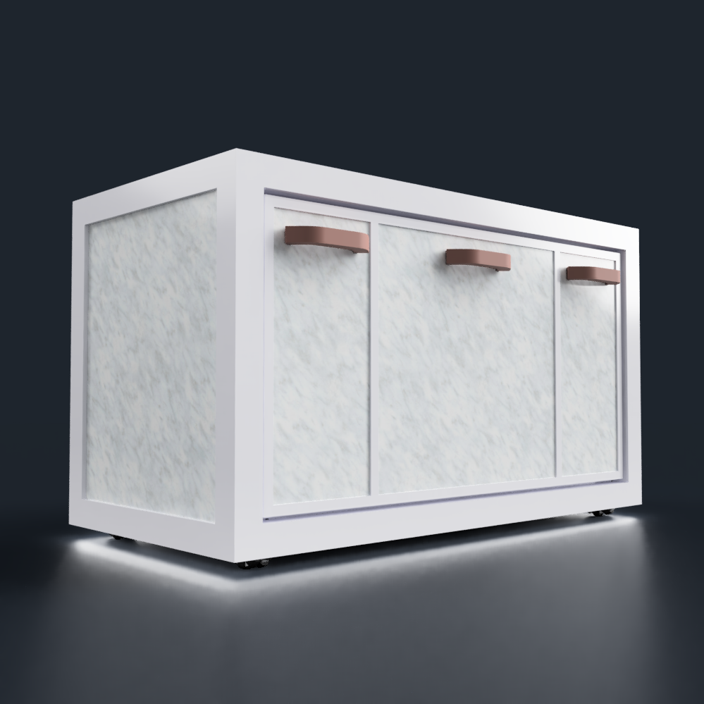 Doesn't look as glamarous but those are the ergonomic rules and consumer expectations that I'm not about to go against. Now I know it looks like 3 seperate doors, but it's actually 3 seperate tiles in a single door, since each tile is 60 x 60cm and the printer is now 64 x 128cm in floorspace.


Hello, I just found this article here that made remember of your project: https://pubs.acs.org/doi/10.1021/ac403397r
Dunno if you already saw it, but I think it is worth the read :)