Close
0%
0%

RR1: Real Robot One - a DIY Desktop Robotic Arm

RR1 is an open-source, 6+1 degrees of freedom desktop robotic arm, mostly 3D-printed with joints powered by custom planetary gearboxes.

Public Chat
Similar projects worth following
RR1 has 6 (6 joints + 1 for the gripper) degrees of freedom and is powered by stepper motors. It is fully closed-loop, i.e. every joint has its own encoder and at any time we know the current angles of all joints. The important feature that distinguishes RR1 from other similar projects is that each joint has its own custom-built 3D-printed split-ring planetary gear reducer. The robot consists of two parts: (i) the RR1 arm itself and (ii) a control computer called Real Box One, or RB1 in short. This allows for having lot of electronics separated from the arm and supports modular design.

The first prototype, called "revision 1" is already running. The second prototype "rev. 2" is on the way (you can try to guess its color). As I gained huge experience during the assembly of "rev. 1", the second prototype "rev. 2" (the orange one) will be much improved in many aspects.

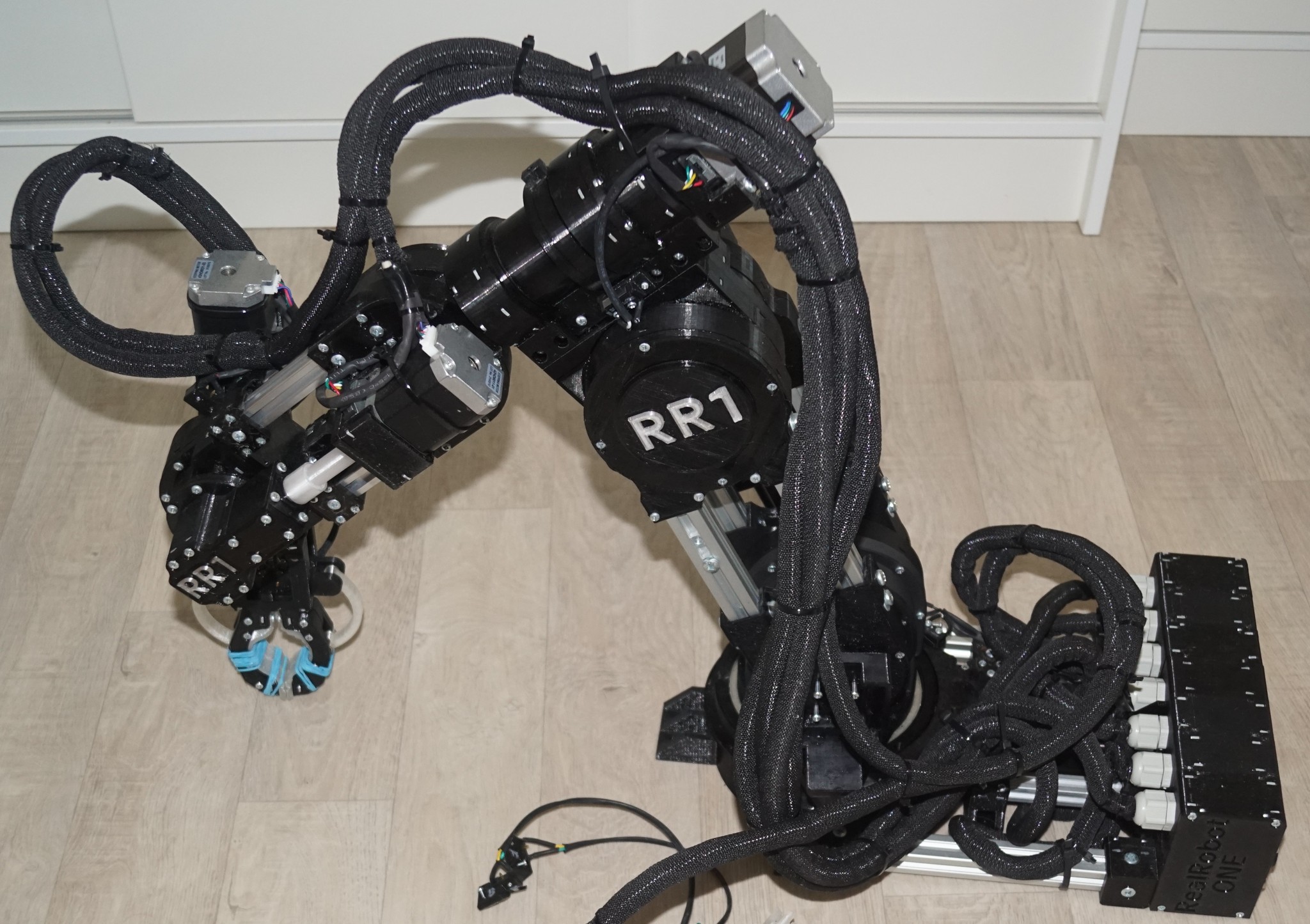
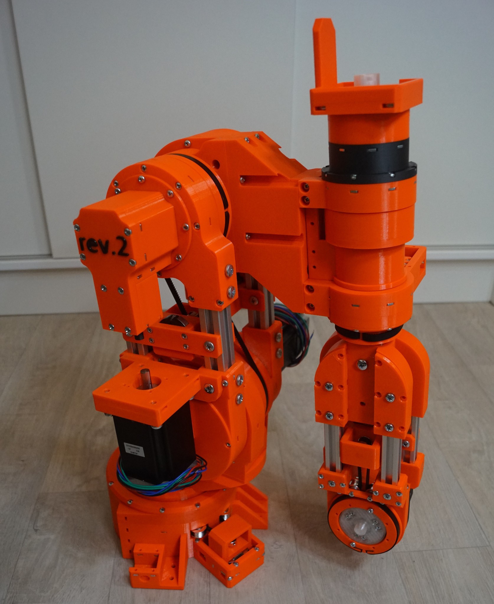
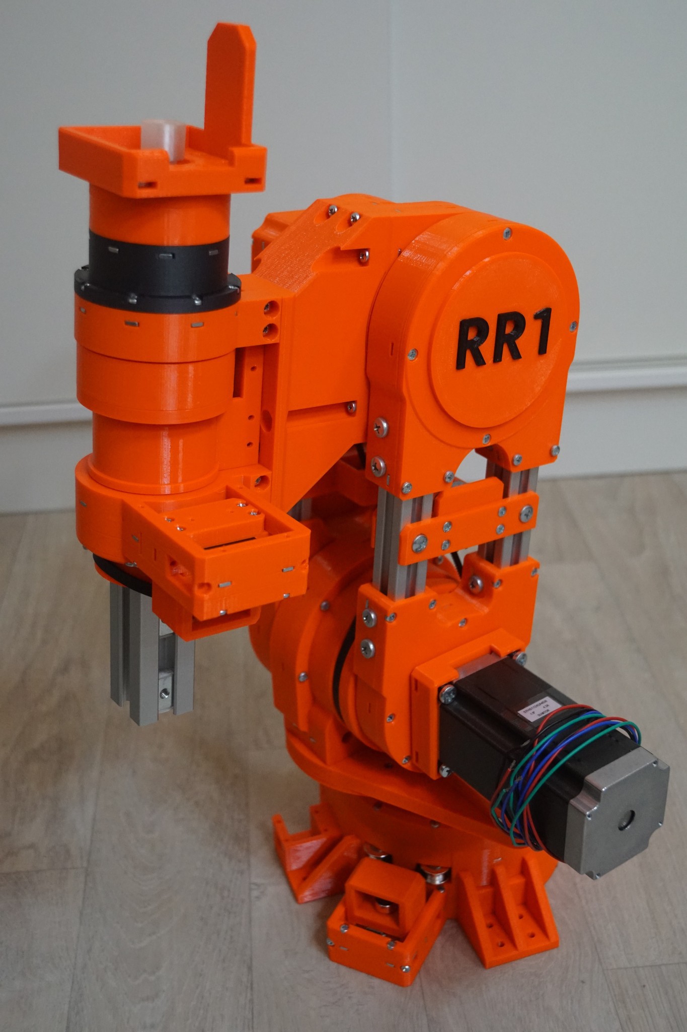
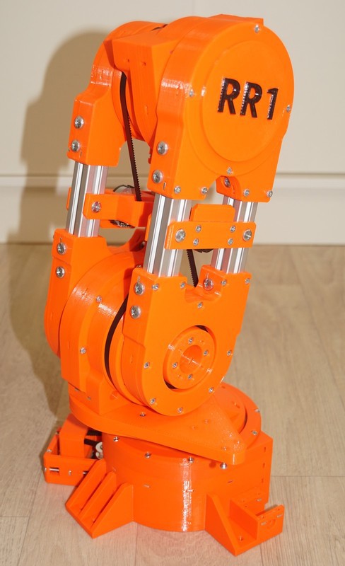
RR1 is a DIY desktop robotic arm, my big project in robotics. The overall design follows the idea of being able to produce more of these robots so that multi-robot coordination on the desktop is possible. I think, having a small scale Industry 4.0 on the table could be great for research and testing.

The robot itself is bigger and more capable than toys but it is not too big like industrial robots and not that expensive so you don't need to have a budget for building a factory if you want 10 of these robot.

Thanks to its small size RR1 is not dangerous like industrial robots that need to be enclosed in an inaccessible area. RR1 can be well used as a collaborative robot.

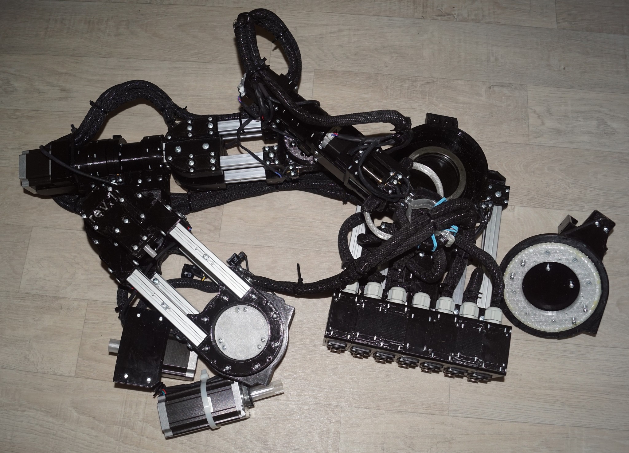
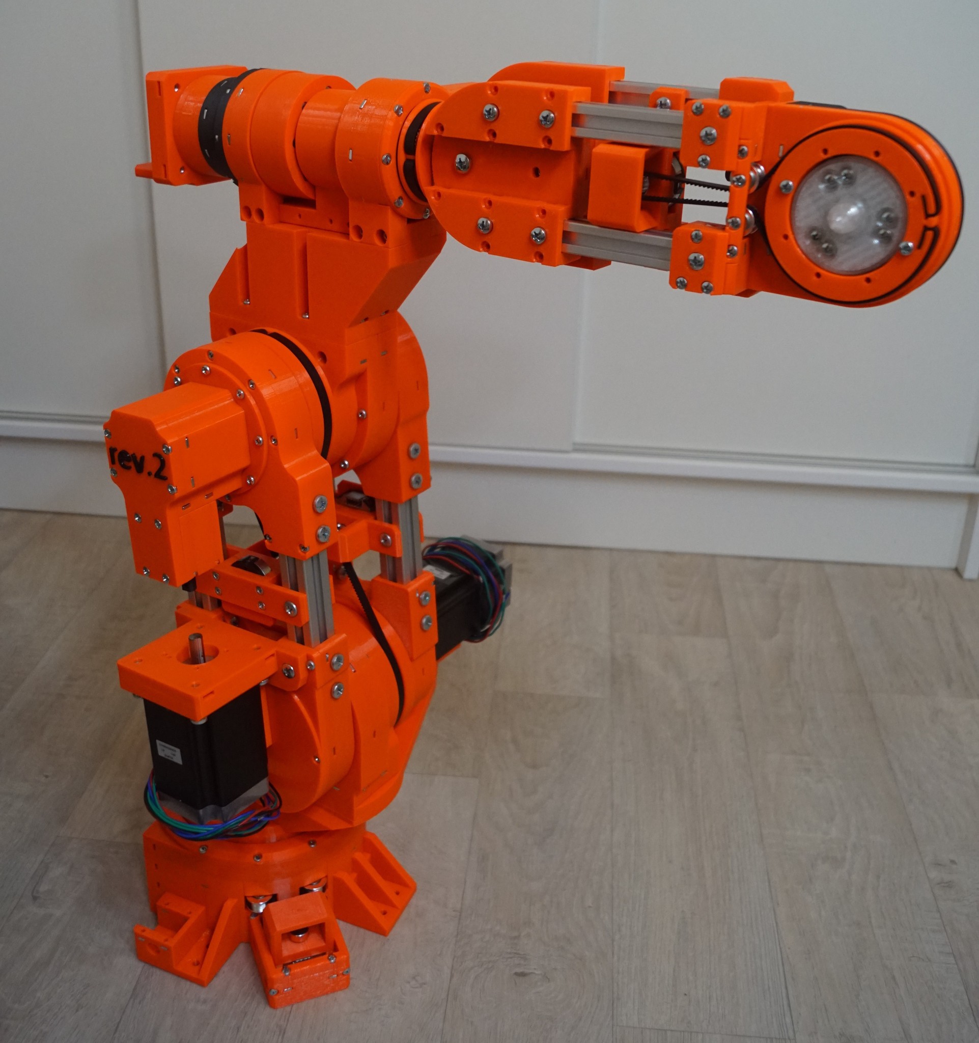
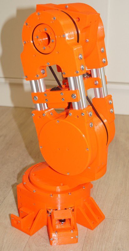
Unlike other robotic projects of similar size, RR1 does not use any belt for torque transmission. All the torque transmission in RR1 is done via gears. All reducers are custom built based on 3D-printed split-ring planetary gearboxes. Each joint has its own planetary gearbox, so altogether there are a total of six similar gearboxes of various sizes across the robot. In addition to this, there are three bevel gearboxes to transmit torque through 90° from the motor shaft, also mostly 3D-printed.

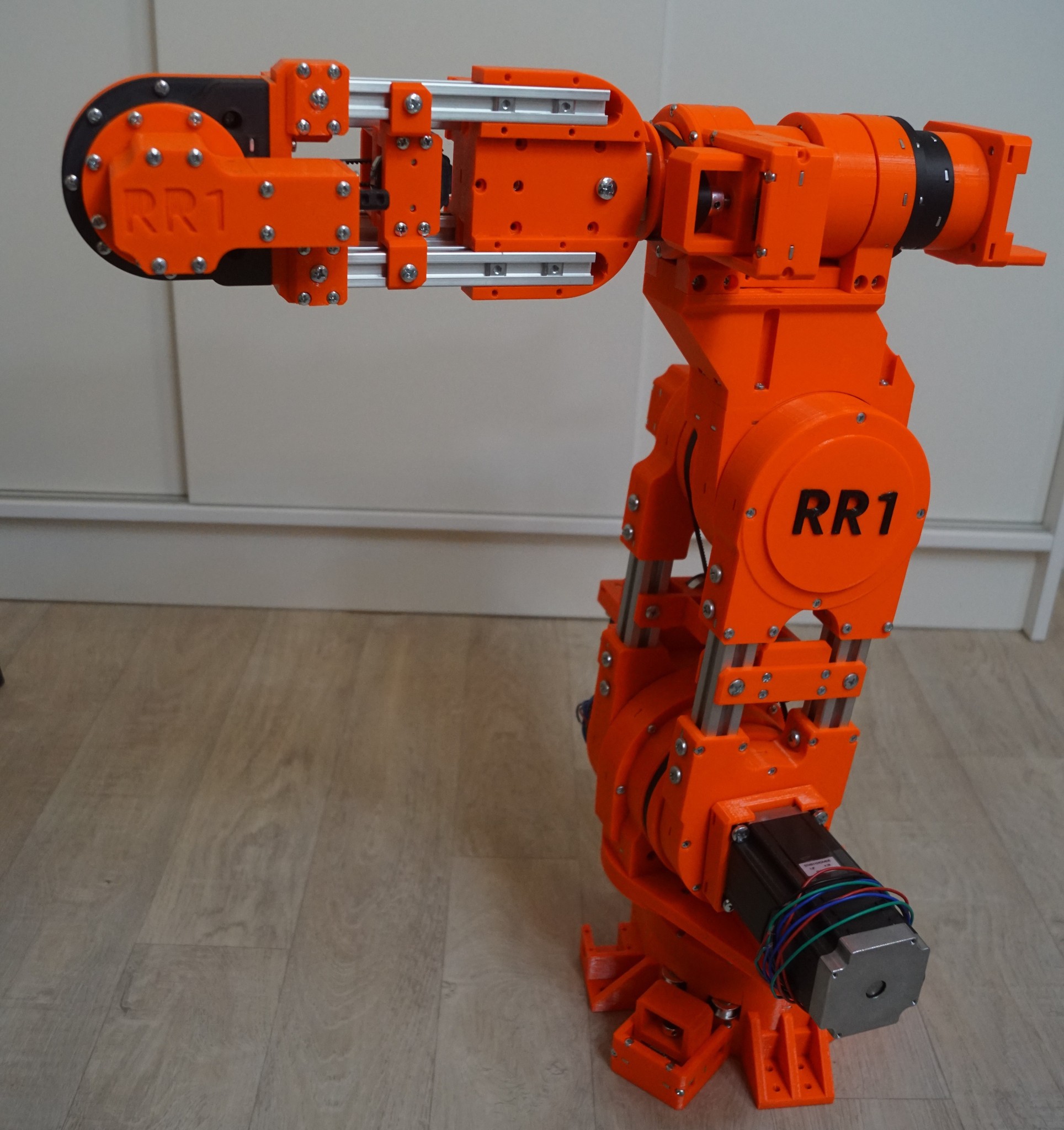
The robot is powered by stepper motors, 4 big (nema 23) and 3 small (nema 17). The lower main joint is powered by the biggest nema 23 stepper motor available (112mm length) generating 3Nm connected to 1:40 reducer which in theory generates torque of 120Nm in the main joint, pretty enough to move the robot.

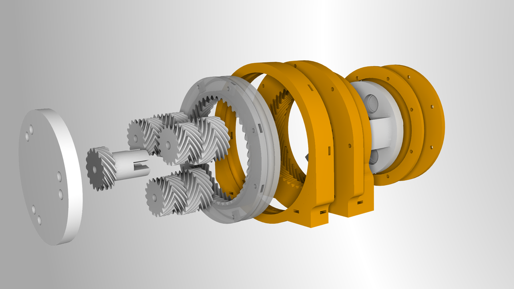
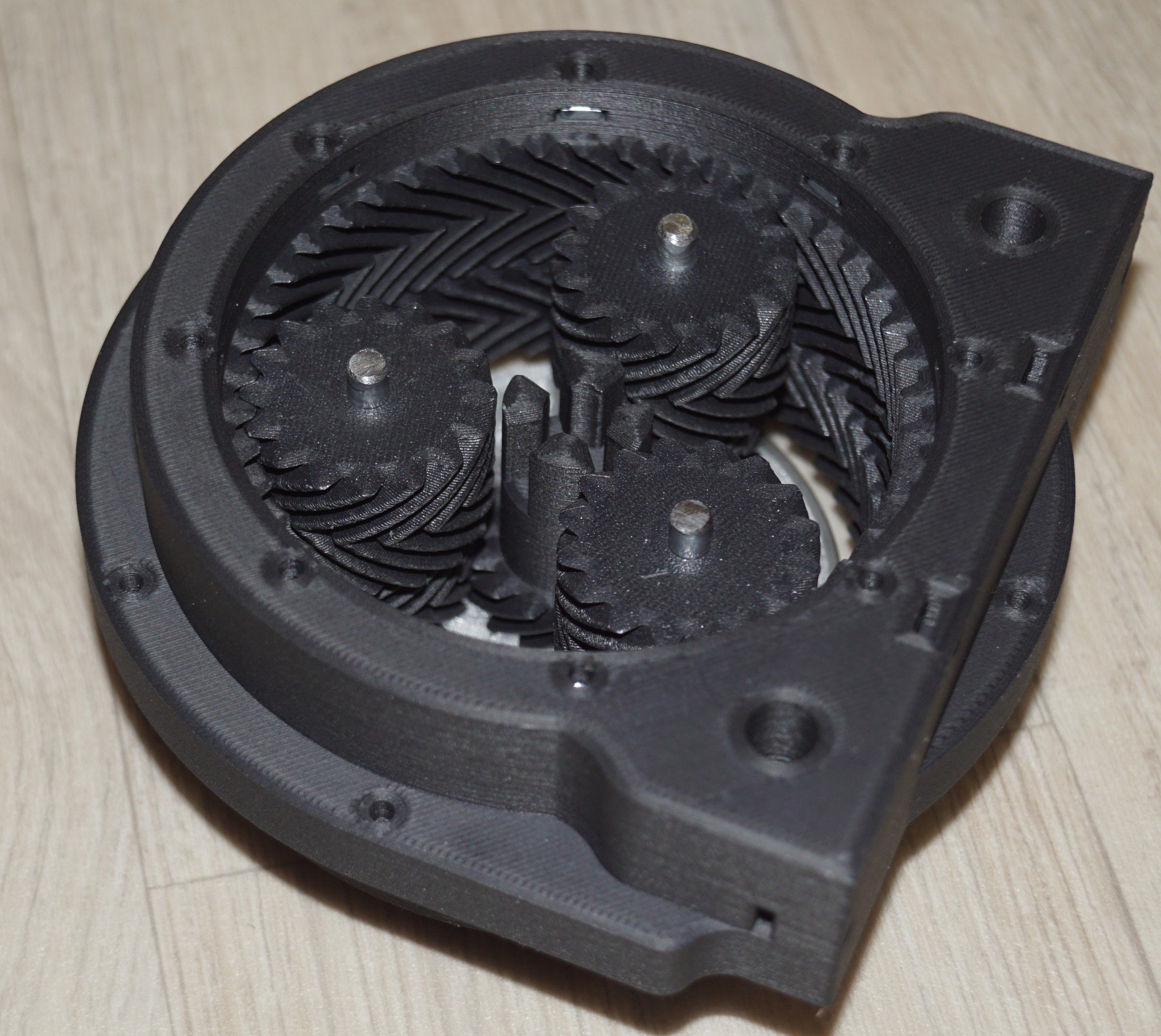
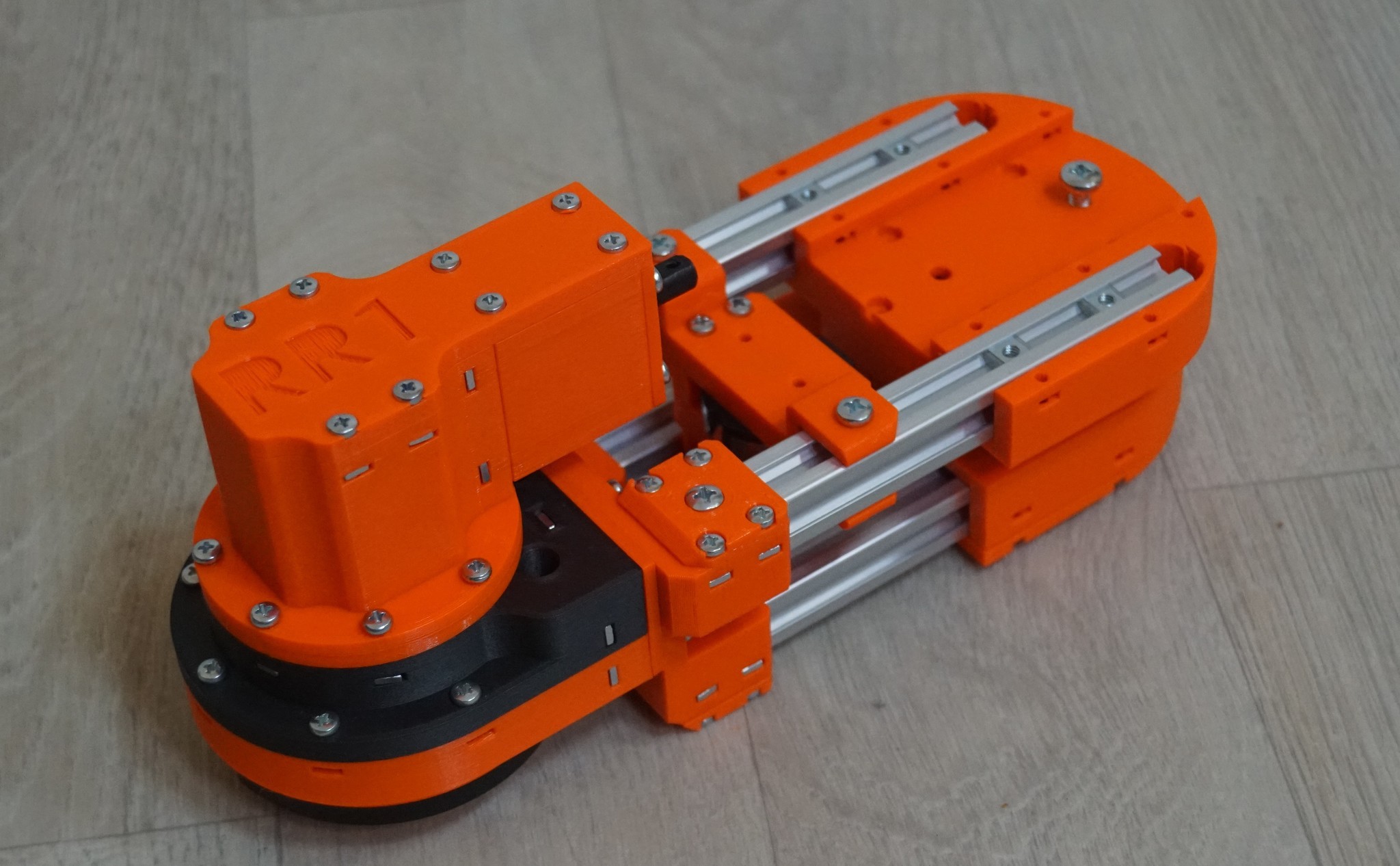
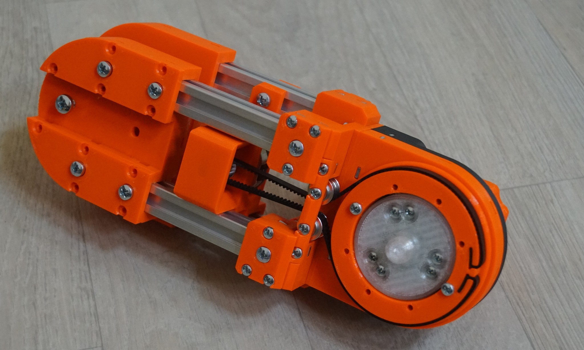
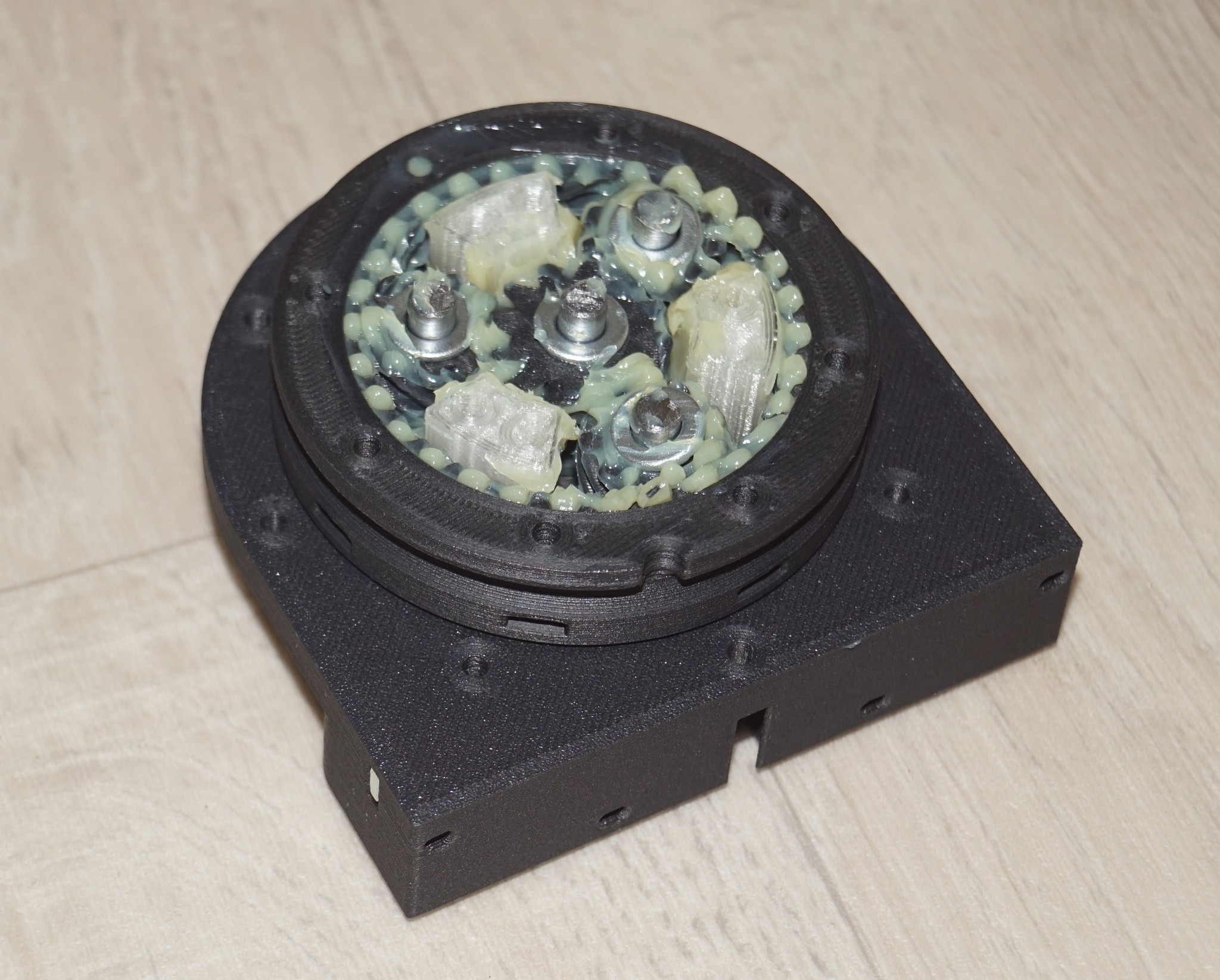
The reducer for the main lower joint is shown in the following figure. It is a split-ring planetary gearbox consisting of 3 planets - herringbone gears - and one middle sun gear connected to the motor axle. There are two ring gears - one fixed (the orange one) and rotating (the grey one). The rotating ring gear that moves the arm is fixed using bearing balls into the groove in the front orange part (balls and bolts are not shown).

NOTE: I often use the term planetary gear box for the split-ring planetary gear box. There are only split-ring planetary gear boxes in RR1 rev. 1 and also in RR1 rev. 2. The advantage of splitting the rings in the gear box enables higher reduction ratios.

The following video shows the assembly of the split-ring planetary gearbox from 3D-printed parts.  The assembly process focuses on smooth rotation and backlash elimination at the same time which is a very challenging task.

The robot currently exists as the first prototype called "revision 1" or "rev. 1" in short. There is still some backlash in the joints of "rev. 1", I expect to eliminate it in "rev. 2" (almost zero backlash has been indeed achieved in the above video). The repeatability is still improving.

Tests and findings with the first prototype "rev. 1" are posted below.


The first test, called the "Coca-Cola Test" is focused on the dexterity of the robot where all 6 joints plus the gripper are employed. RR1 is lifting 330ml Coca Cola and simulates pouring. The can is full and it turned to be somewhat slippery for the robot's gripper. This can be mitigated by the blue rubber bands on the gripper which has anti-slip effect. It seems I should add more anti-slip components into the next revision (rev.2) of the gripper so that rubber bands can be eliminated.

Another video showing articulation of the robot follows. This test is also focused on checking if all cables are long enough to allow the arm to twist round.


I also did some preliminary weight-lifting tests in which RR1 lifts a water barbell. I was wondering if the robot can handle the full 1kg barbell - in theory it should. The following videos shows the test. The next video shows motion test with an empty barbell - this is very easy to lift:


And the full 1kg barbell test in the next video (Sonic the Hedgehog has been caught by the robot too). As the video shows, RR1 is capable to lift 1kg in its gripper, that is using its wrist. It seem we can meet the projected...

Read more »

RR1_3D-printed-parts-bundle_rev.2.zip

3D-printed parts for RR1 rev.2 in the STL format.

x-zip-compressed - 20.61 MB - 08/21/2023 at 22:16

Download

  • 1 × Nema 23 Stepper motor 112mm
  • 1 × Nema 23 Stepper motor 80mm
  • 1 × Nema 23 Stepper motor 76mm
  • 1 × Nema 23 Stepper motor 54mm
  • 1 × Nema 17 Stepper motor 59mm

View all 9 components

  • All STL files for 3D-printed parts of rev.2 in Github

    Pavel Surynek08/21/2023 at 21:59 0 comments

    I am happy to announce that all STL files for 3D-printed parts of rev.2 are published in my Github reposity: https://github.com/surynek/RR1. I have not yet published the source files in CAD, I will send them on request for a specific part (sometimes parts need to be adjusted by a few tenths of a millimeter for a specific 3D printer). The design of the RR1 robot represents lot of work for me, so I don't want to make the sources completely freely available (at least for now).


  • RR1: The Documentary

    Pavel Surynek08/13/2023 at 20:38 0 comments

    Together with my colleagues from the Faculty of Information Technology, ČVUT, we filmed a new documentary about the RR1 robotic arm in our well equipped faculty studio. Unlike my previous videos, this one is more professional, better lit and shot with better cameras. In addition, I show things in the video that I have not shown in other videos.

  • Gripper for the RR1 rev. 2

    Pavel Surynek08/06/2023 at 13:38 0 comments

    I finished assembling the gripper for the RR1 rev.2. Most notably each finger of this new gripper has two parts connected by a joint, so it is much more dexterous and can grip an object much better than the fixed gripper in RR1 rev. 1. I also improved friction, the inner surface of the gripper has many small inti-slip pads (rubber bands as in rev.1 are no longer necessary). I did a test and, for example, the gripper is perfect for holding a glass or a can. The tip of the gripper when closed can operate as tweezers.

    As for the material, it is a combination of PETG, flexible filament and polycarbonate with carbon fiber. Plus some linear bearings many screws and bolts.


  • Gearbox Replacment after a Crash at Maker Faire Prague 2023

    Pavel Surynek07/01/2023 at 22:27 0 comments

    After running the RR1 rev.1 (the black one) at Maker Faire Prague 2023 for two days, we experienced a crash of the main shoulder gearbox. One of the axles holding the planet gear moved out and the planet went out of its position which resulted in an irrepairable collapse of the gearbox. So I made a new gearbox, now not from PETG but rather from polycarbonate blend with carbon fiber (Prusa PC blend).

    Replacing broken gearbox of the main joint means decomposition of the robot into quite small parts interconnected via cables.


    The new gearbox ready for assembly into the robot.


    And finally everything assembled together again. The new gearbox improved rigidity of the robot which made RR1 rev.1 even better than before. After this incident I decided to replace the big gearboxes of the shoulder and the elbow joints in rev.2 (the orange one) originally made of PETG with new ones made of polycarbonate blend with carbon fiber (Prusa PC blend).

  • rev. 2: The Elbow Link Done

    Pavel Surynek05/30/2023 at 22:50 0 comments

    I have some good progress on the rev.2. The elbow link is finished and mounted on the rest of the arm. The following figures show what does it look like. The elbow link is shown separately, the rest of
    the arm separately (in a folded position), and finally the elbow link and the rest fixed together.

    The encoder nicely fits between the aluminum extrusions on the elbow. Parts of the wrist joint are again made of PC blend with carbon fiber (the black parts) - all the gears and rings in the gearbox. The reduction ratio for the wrist joint is approximately 1:10. Much less than in rev.1 which I believe can make the robot faster without compromising its strength. Another notable improvement from rev. 1 visible in the folded position is that the elbow link can rotate freely without touching the upper-arm link.

    Now it is time for finishing the base turret and the wrist link with the gripper. Some important design changes will come on the wrist link as well.

  • Completing Gearbox for the Wrist Joint

    Pavel Surynek05/20/2023 at 10:29 0 comments

    There is some progress on rev.2: not big but steadily going ahead... I am just completing the gearbox for the wrist joint which is one of the smaller joints on the RR1 robot (the second smallest to be exact). The picture shows well lubricated planetary mechanism for the wrist joint without the disk that will cover everything and the outer ball bearing ring that will go aorund.

    Most notably, I switched from PETG to polycarbonate with carbon fiber (Prusa PC-Blend Carbon) for some machanic parts of rev.2, namely for gearboxes on the elbow and the wrist which seems to give much better results. Gears made from PC are very tough and feel like even not plastic. If I compare big shoulder and the elbow joints on rev.2 where mechanic parts were made from PETG, this is big improvement. Ovearall backlash is reduced in the mechanism and visual look and feel is much more pleasing than PETG.

  • New Base Turret with Encoder on the Base Joint

    Pavel Surynek04/07/2023 at 09:19 0 comments

    The progress with RR1 rev.2 is not as fast as I would like it to be, but at least I can show some new designs concerning the base turret. Currently the main link connecting the base joint (shoulder joint) and the upper joint (elbow joint) is mounted on the redesigned base turret as can be seen in the photo below.

    The main new feature of the base turret is that the encoder is moved from the motor shaft directly next to the base joint. The torque is transmitted to the encoder via belt that goes all around inside the base turret. The belt is directed out of the base turret towards the encoder by two pulleys (see photo below).

    I expect higher precision from this design and as I wrote before, also increased collaborative ability.

  • Moving Encoders from Motor Shafts to Arm Links

    Pavel Surynek02/12/2023 at 23:57 0 comments

    The revision 2 of the RR1 robotic arm is progressing. The experience from rev. 1 tells that having encoders on motors shaft does not give enough accuracy, so I decided to move encoders from motors to arm links as shown in pictures (the pictures show two main joints of the arm and the link between them). Fortunatelly the design of RR1 is quite flexible so this change could be smoothly integrated in the current design.

    The encoders are fixed to aluminum extrusions representing the link above or below the corresponding joint. The torque is transmitted to the encoders via belts from the rotating part of each joint. There is a significant reduction ratio between the joint rotation and the encoder rotation to increase accuracy.


    In addition to redesigning the encoders, there are multiple improvements in gearboxes of the joints. The rotating parts are fixed with more bearings around which slightly increses the weight of the joints but significantly reduces the backlash.

    The precise rotation tracking with the new encoders will futher contribute to reducing any backlash in the joints. I also plan that the new design will allow for more collaboratives modes of the robot such as lead through motion recording.


  • Assembling the Planetary Gear Reducer

    Pavel Surynek08/21/2022 at 12:53 0 comments

    Reducers are a key component of the RR1 robot arm. I use my own custom built 3D-printed planetary gearboxes. The following video shows assembly of the gearbox for the upper joint (elbow join) for the second prototype of RR1 ("rev.2"). There are a total of 6 similar gearboxes of various sizes across the robot.

    As the gearboxes in RR1 use herringbone gears for smoother rotation, the assembly must be carried out exactly as shown in the video. All gears must be meshed together well so that there is not much friction and not much backlash at the same time which is especially difficult to achieve with herringbone gears. The video shows that the assembled gearbox rotates smoothly and has no detectable backlash. Such an achievement requires lot of experience and a very good 3D printer (I use Prusa i3 MK3S+).

    And as you can see "rev. 2" will be orange.

  • Speaking about the RR1 Robot

    Pavel Surynek08/14/2022 at 12:06 0 comments

    This is a talk a had at Prusa Lab in Prague in June 2022. It is in Czech so probably only for the Czech audience but at least it shows me how crazy I am about robotics.

View all 13 project logs

Enjoy this project?

Share

Discussions

Similar Projects

Does this project spark your interest?

Become a member to follow this project and never miss any updates