lion mclionhead
Self supporting semi rigid air ducts are $50.
https://www.mscdirect.com/product/details/76930528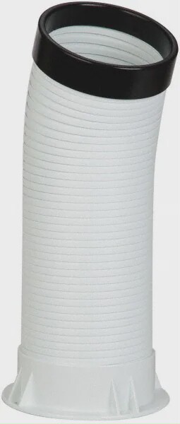
We can make it cost more & automate it.
An update to a mighty air vent
Already have an account? Log in.
To make the experience fit your profile, pick a username and tell us what interests you.
Self supporting semi rigid air ducts are $50.
https://www.mscdirect.com/product/details/76930528We can make it cost more & automate it.
https://www.loftedaero.com/product-page/f-35b-three-bearing-swivel-module-3bsm
3 years after the lion kingdom's foray, the goog started hitting more widely available kits which existed in 2018. Such is the latency of page rank search algorithms.
Feels kind of silly to bother with all these micros, encoders, bootloaders when others are just using normal 180 deg servos & getting faster movement. It may not be as precise. 1 thing it does right is synchronizing 2 servos. This is only possible with a stick controller. This vijeo got 58000 views while the most a lion ever got was 2000.
This kit costs $300, but cheaper servos would get it down to $200.
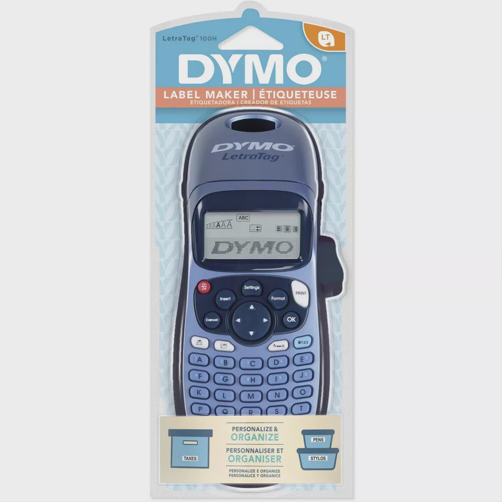
It looks like the label printer is going to be key for some remote control functions.
This is a really trashy label printer, but it was the cheapest. The labels don't stick to anything. The resolution is real low. The refills are a small fortune.
The motors are still browning out, despite using a lot less current than the 1:75's. It could be the wire gauge. It could be cold weather causing parts to bind. The CPUs still aren't browning out though.
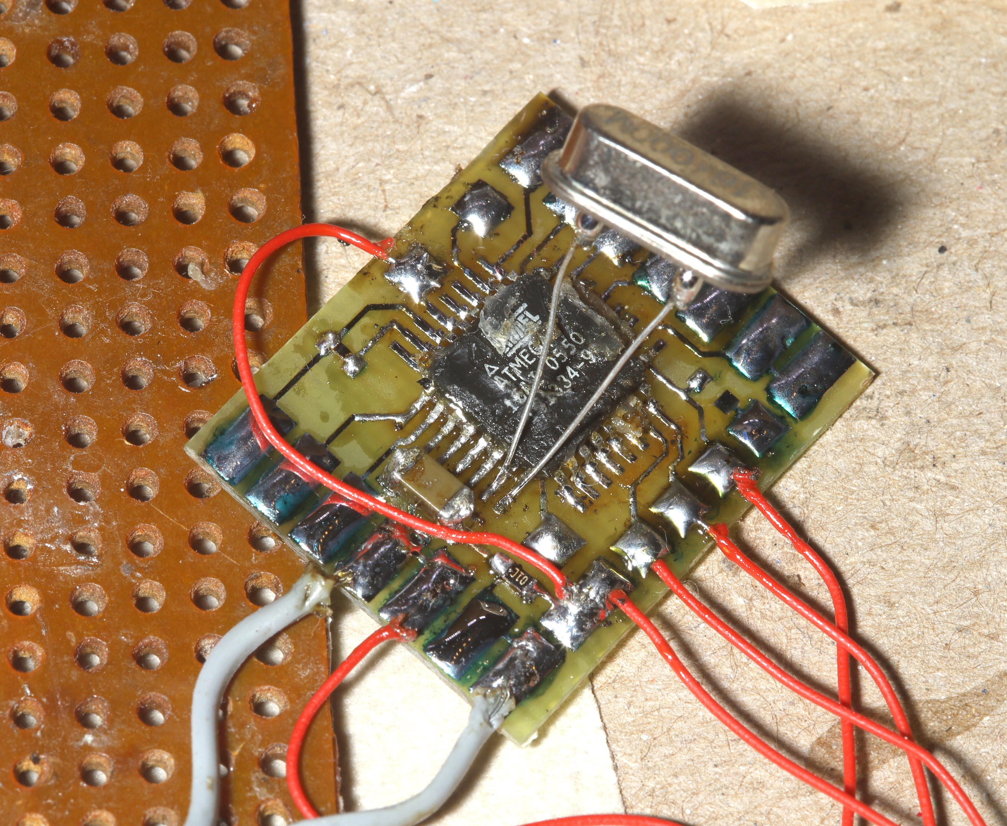
The biggest problem is the encoders drifting. It seems the 8Mhz atmegas aren't fast enough to catch all the pulses. The thing will have to move to faster microcontrollers, but fortunately, it's a lot easier to create a single wire bootloader for a PIC than an atmel.
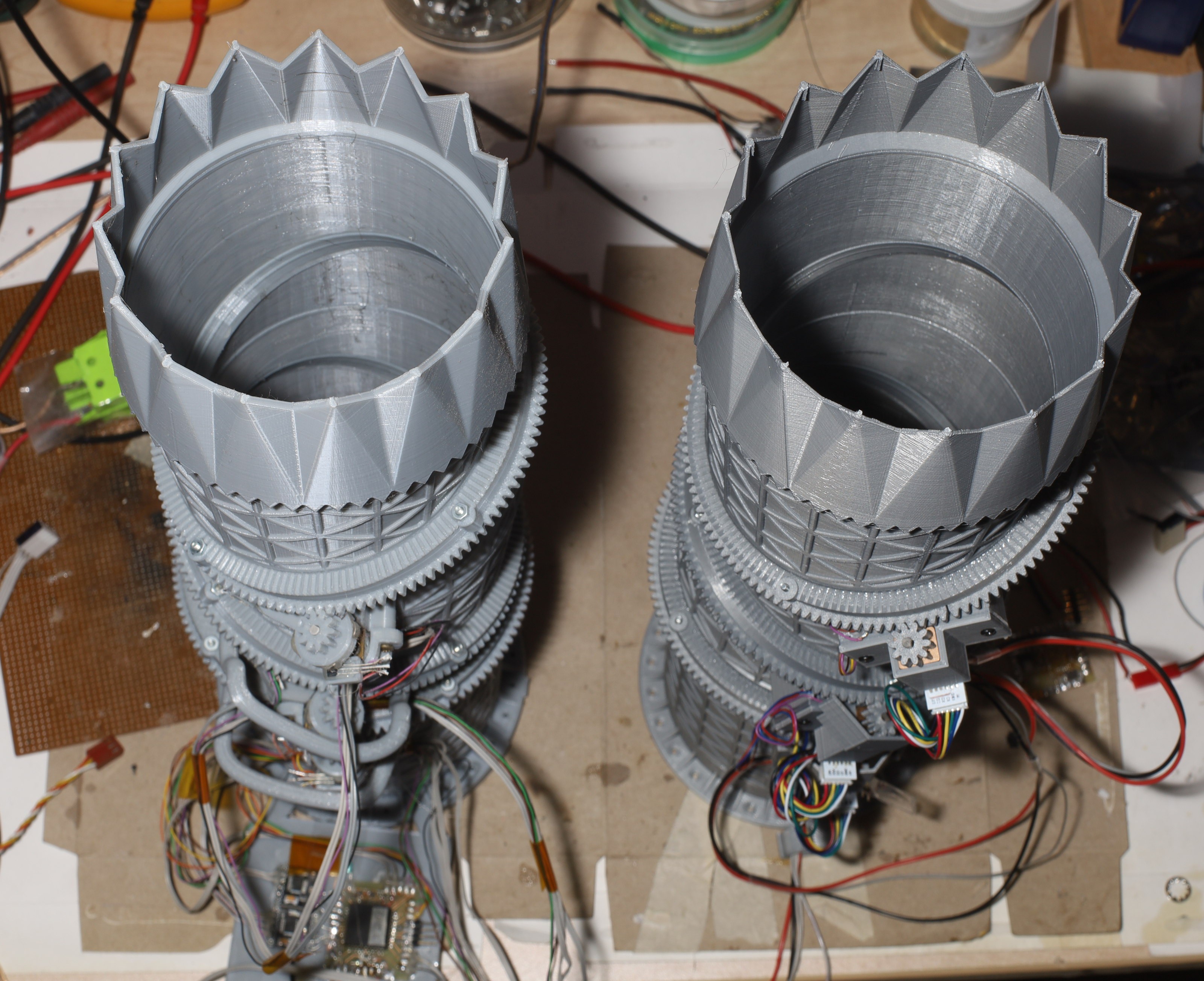
Nozzle 2 is a lot quieter. 1:298 seems to be the required gear reduction for accuracy & braking. The sigmoid curve seems to give the right step size. The slow speed is negligable because large movements tend to be only made by presets. For small movements, the speed isn't noticeable.
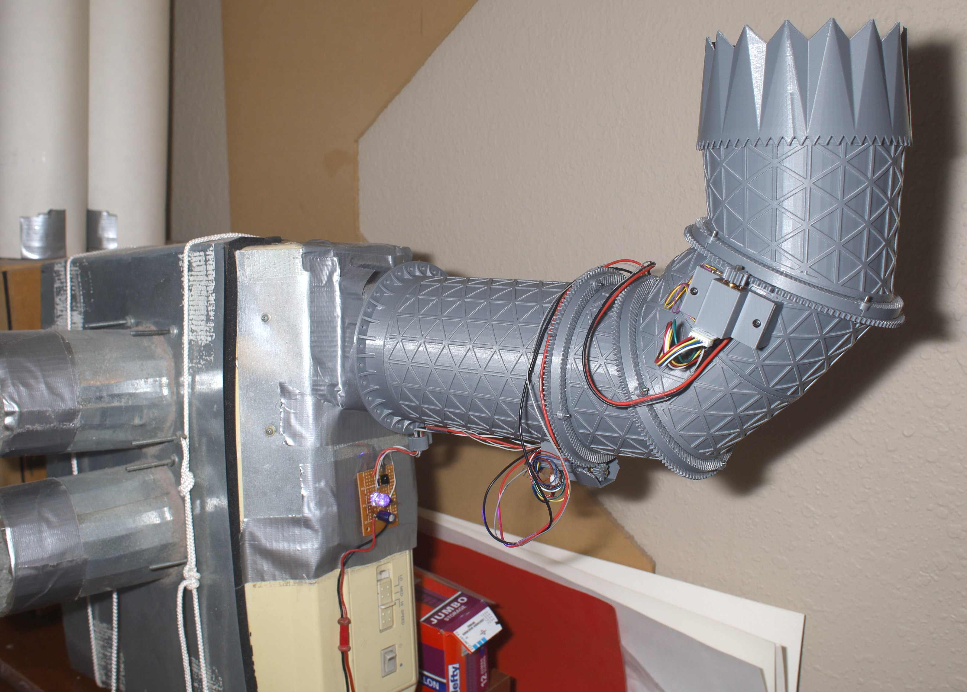
1:75 wasn't enough to hold it in a sideways right angle. 1:298 gets the job done.
It took a long time to enable the full range of motion with nozzle 1 because it requires the user to manually center it before arming it & there was a good chance lions wouldn't remember. After the psychological barrier was broken, nozzle 2 has the same full range of motion.

Nozzle 1 was quickly scavenged. It was the lion kingdom's 1st 3D print & represented the level of skill of a 1st 3D printing design.
There was once a dream of making a manually positionable version of the nozzle. It could easily be done with nozzle 1's remanes. It would need some spring loaded pins in place of the motors to lock the gears. The gears would have to be axially facing. The manually positionable version was intended to become a desk fan, fume extractor, or go near a pool.
There already is a desk fan which works quite well. The nozzle doesn't cover a big enough area to make a good desk fan. There's not enough room for a fume extractor that big. There's still no day job requiring another blower. A blower compact enough to use near a pool would be real noisy & the nozzle wouldn't be as portable as a bare blower on a gimbal. It's generally too big for any application besides what it was built for. It was sized to match a self supporting air duct.
So the lion kingdom reluctantly decided to scrap it. A new one can be printed at any time.
Noted with the sigmoid table that the nozzle zigzags a lot when taking the large steps, but what really matters is getting the maximum precision in pitch, not whether some steps are too small or whether it zigzags when moving.
The decision was made to desolder the programming headers from the 2 pitch motors & install it on the blower. The pitch firmware never had any problems so it won't be receiving a bootloader. 1 final check of the boundary sensors showed a lot more sensor margin with the 2 pitch motors than the yaw motor & the yaw sensor is only used in the position where it gives the strongest signal so that covered any new motor mounts.
Of course, the brain board's programming header breaks all the time. There's kind of a need for either a bootloader or a more robust programming header.
The mane bugs are simultaneous homing of the motors fails when it's horizontal. Boundary sensor 1 glitches when all 3 motors are going, maybe because of the current draw. The homing has to be 1 motor at a time. The glitch is a single analog report in the 140's or the 90's.
The 1st preset after homing goes to a fully deflected pitch before going back to straight & then going to the requested preset. The later presets work.
The segments aren't aligned when pitch is fully deflected. It might need new values for ENCODER_MAX.
Communication needs to be hardened so when it gets a packet intended for another board it waits for the entire packet to finish before waiting for a start code.
These were rare enough use cases to be ignored.
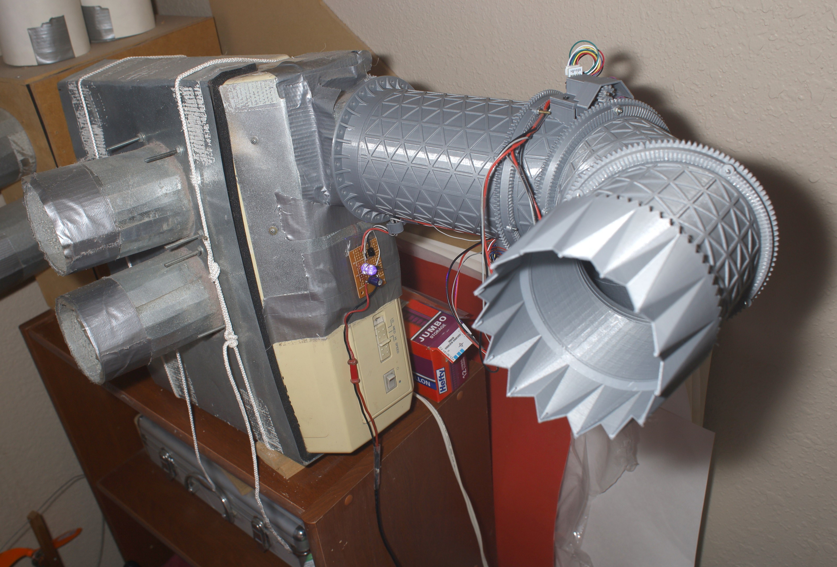
A final view of nozzle 1 before it's sent to landfill.
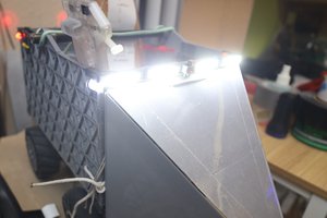
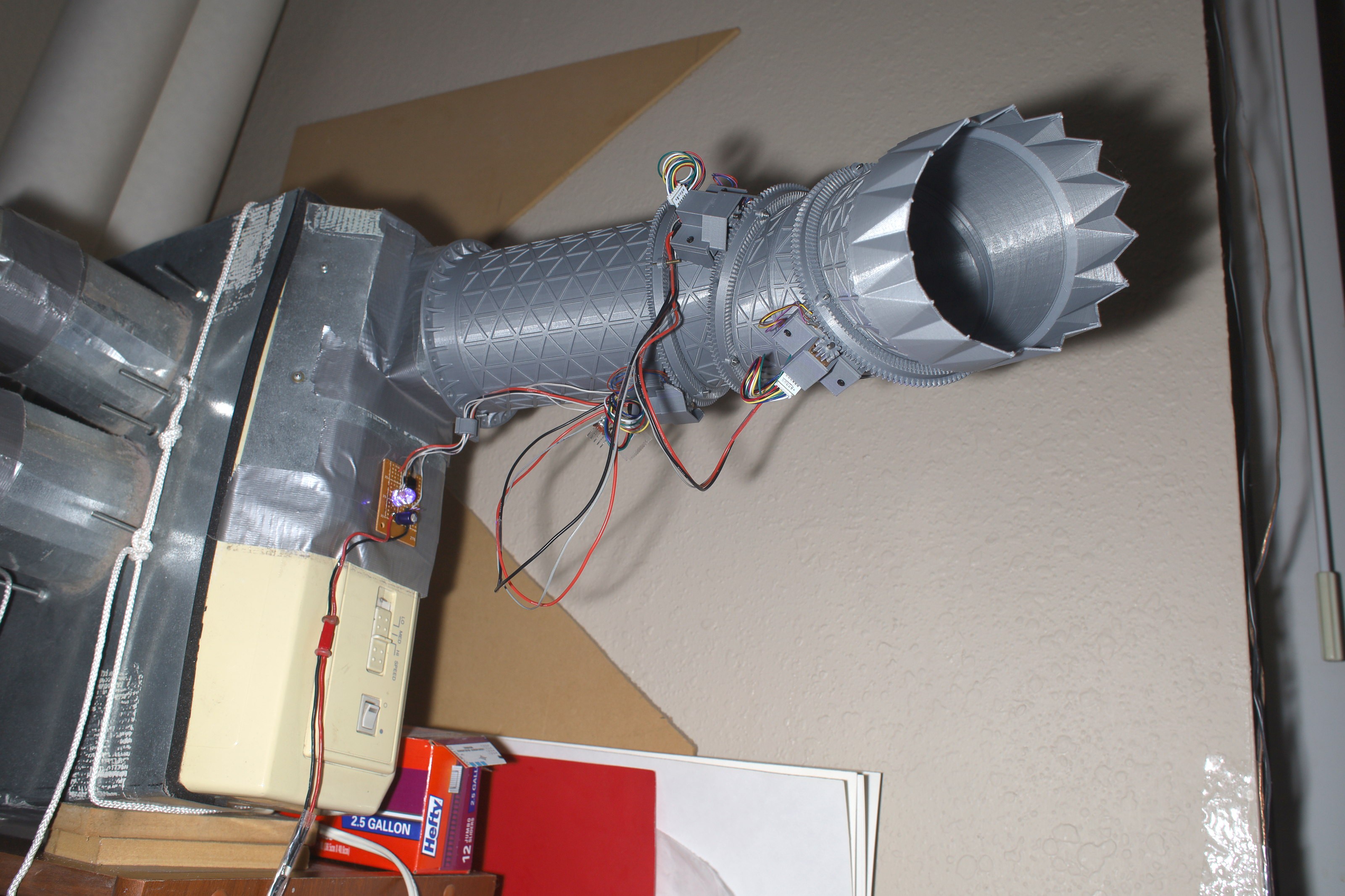
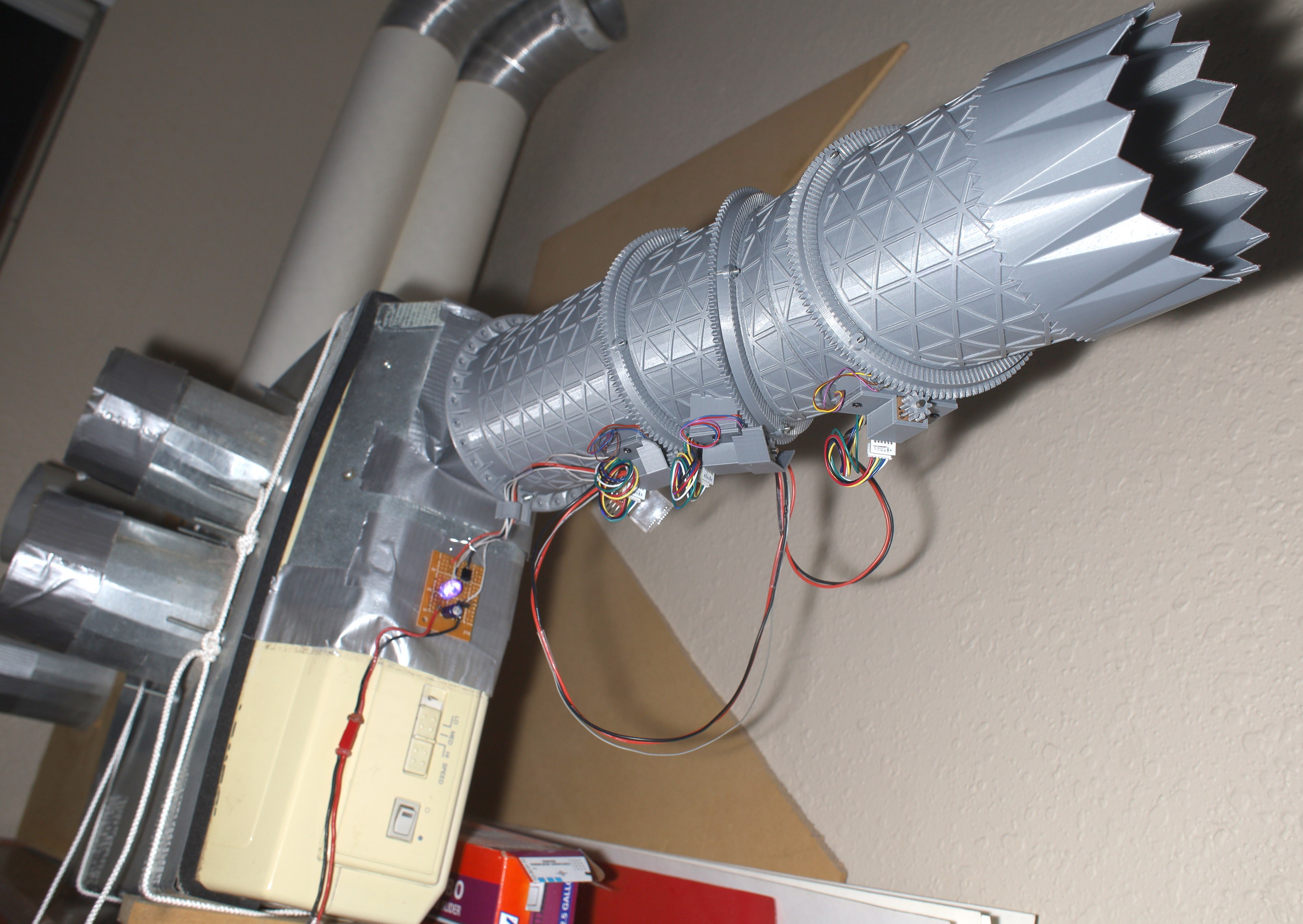
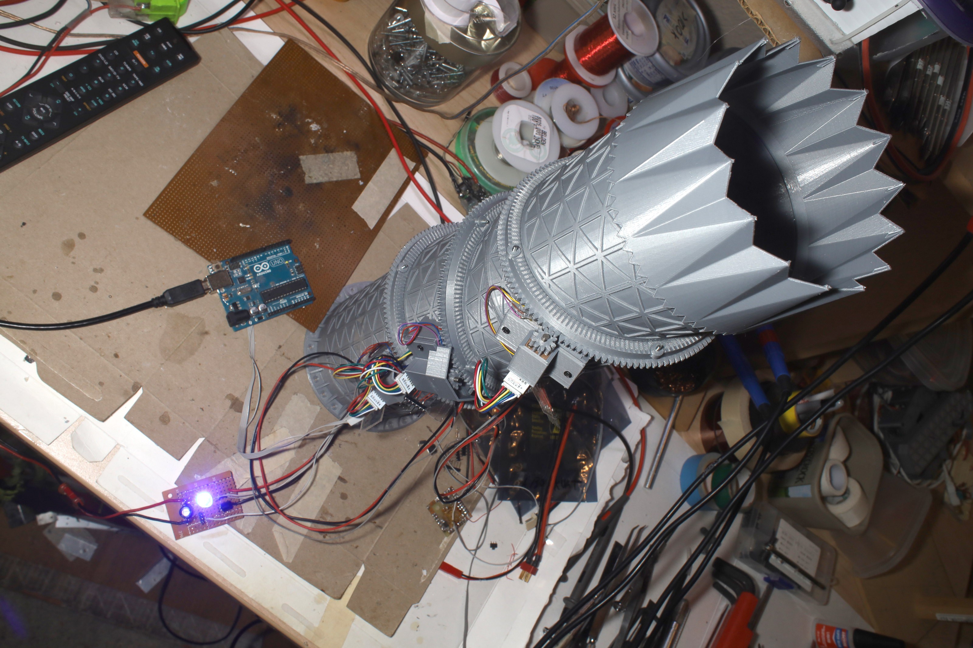
Horizontal mount was resurrected for testing. Any condition not tested on the bench is a failure mode.
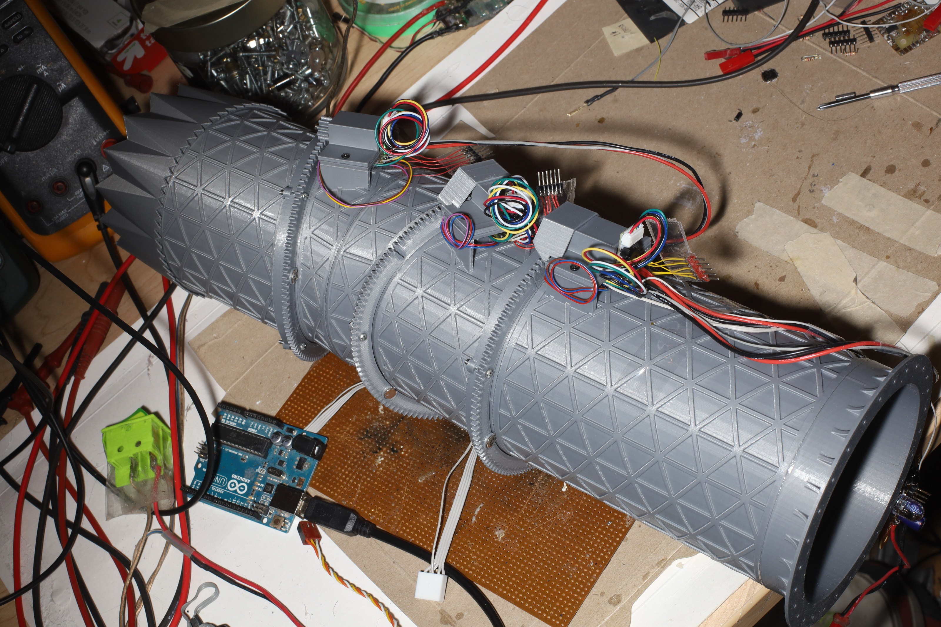
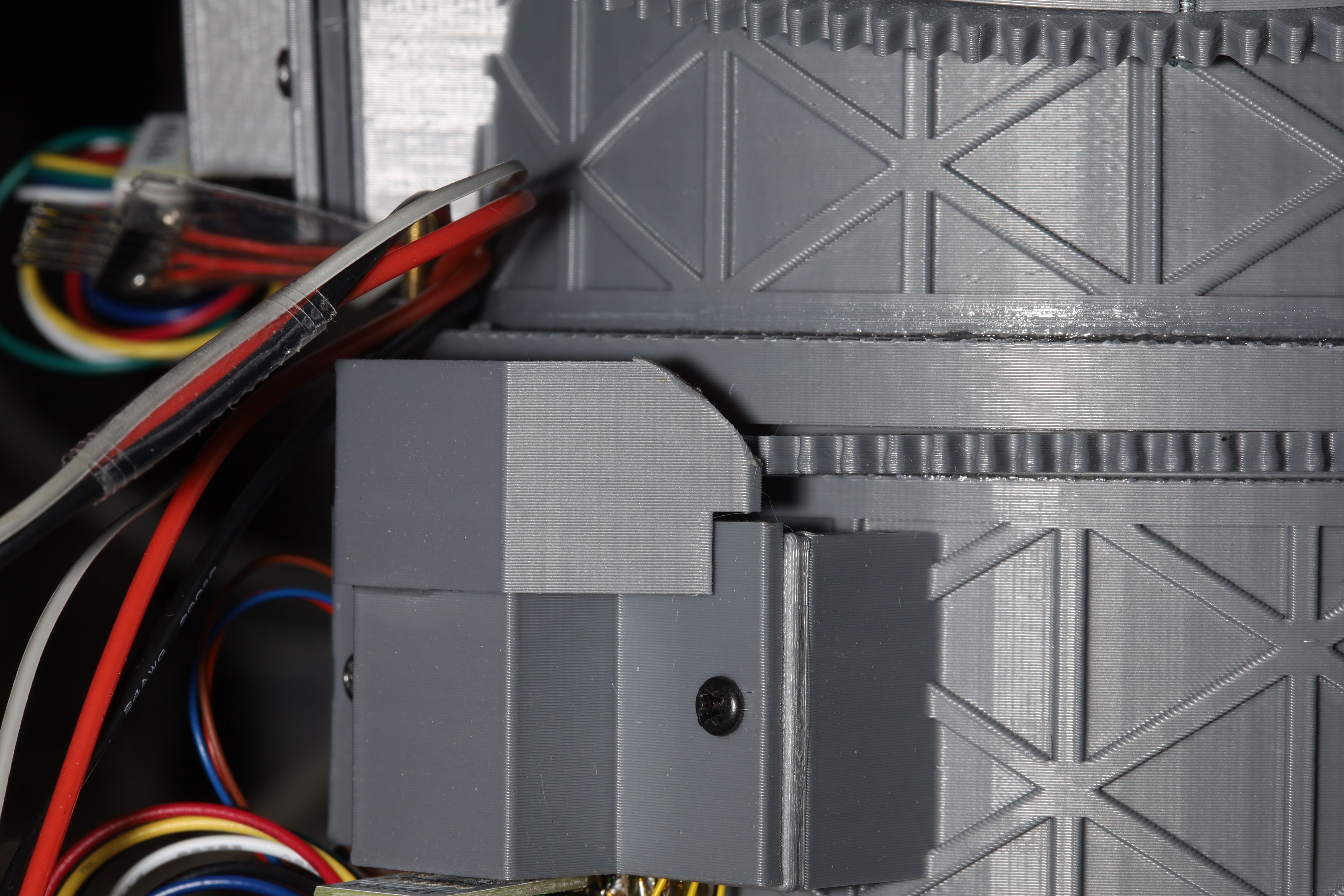
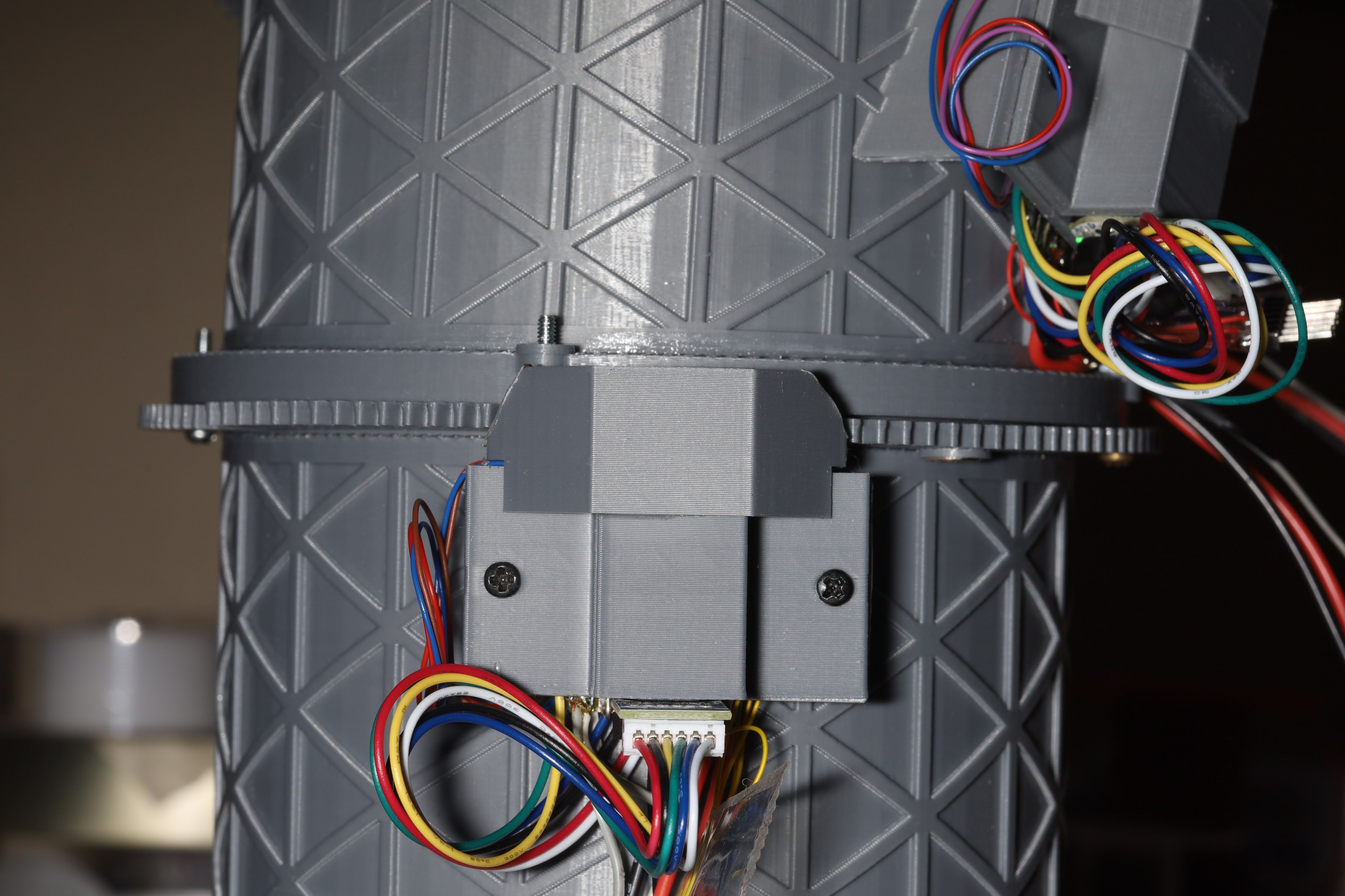
Final installation.
The preset code was manely a straight copy from nozzle 1. The mane thing this did to achieve smooth motion was to poll outside of motor_tracking for motor movement & start the next step if it's reading a preset. The repeat code checks inside motor_tracking for motor movement & then starts the next step if it's repeating. It's sort of a mess.
There was an attempt to move the nozzle yaw & pitch in 1 step but it made the nozzle point in unintended directions for too long. Presets are very slow with 1:298 motors.
There's a lot of back tracking when it finishes a pitch move & starts a yaw move. The motors are overshooting, maybe because they're polled at only 30Hz or maybe because of mass. 1:298 might be the minimum amount of precision despite the slowness.
The next task was using a sigmoid curve instead of linear interpolation to make the pitch movement more even. This sort of evened out the size of the steps, but now some of the steps in the middle are too small. There needs to be ongoing tweeking.
The motor arming got changed to go in 1 step, but this revealed a bug in nozzle 1 where by a motor could find the boundary sensor, reverse direction to find the HOME position, & never stop. It wasn't continuing past the boundary to make sure the direction reverse crossed the boundary again.
It's been an incredibly slow process, on account of the atmega328 tools & the complex 3 board design.
It seems no-one either uses arduinoISP outside a classroom & no-one hacks their arduinoISP to use a higher baud rate, since setting the baud rate to 115200 has been part of the failures. The arduino library might be too slow to handle anything over prehistoric baud rates.
The boundary magnets had to be rearranged again into alternating sides of the motors.
In going from straight to a right angle, the exit tube goes clockwise. The middle tube goes counterclockwise. To reset without manual intervention, the magnets have to be positioned so the middle tube goes clockwise to hit the boundary & the exit tube goes counterclockwise to hit the boundary.
Then since these motors are much slower, there have to be different rules governing motion when a button is tapped & when a button is repeating. When roll is repeating, it needs to keep the roll motor on instead of waiting for the next repeat event. When pitch is repeating, it needs to wait for tracking to finish & set new target positions from the table without waiting for the next repeat event. It also has to make sure the next pitch step doesn't make any motors back up because the encoders lag the motor movement.
This results in some crosstalk when adjusting roll. The pitch motors sometimes backtrack when adjusting roll because they overshot. The 1:298 motors overshoot a lot because they're being moved in smaller steps. The number of pitch steps was increased from 24 to 64. Despite the overshoot, they're getting just enough precision. Anything below 1:298 probably wouldn't have been precise enough, despite the slowness.
During pitch movement when all 3 motors are firing, current goes to 500mA. Quiescent current is 100mA. There's no easy way to measure the starting current.
Noted in the video that the step size varies from virtually no movement when it's near the endpoints to very large movements when it's 45 deg, hence why the lion is stepping it back & forth. Instead of a higher number of steps, it probably needs a nonlinear step size. It still needs the 1:298 gear ratio & encoders.
The 1mm of play in the bearings causes the hall effect sensors to give wildly varying boundary signals. The motor mounts might need a tweek along with the cable shrouds. The cables snare more often because they're silicone instead of ribbon & the new cable shrouds are junk overall.
Fewer symbols & shorter timeouts were the key to the remote control. The algorithm of using timeouts to frame the code & buffering a complete code continues to be the most effective.
Noted that the boundary magnets have to be 90deg offset from the home positions of the motors. That way when all 3 motors are manually lined up before a reset operation, the motors know which way to turn to find the boundary magnets. The boundary magnets are only used for finding the home position & ignored afterwards. That's why the bearing gears are removable.
The outlet magnet doesn't matter. It's only lined up for consistency. There's so much play in the bearings, the hall effect sensor barely detects anything. The motor mounts might have to be reprinted.
Noted the farsteners for the bearings still have to be bolts. 1 of them has to be longer to manage the cables.
The 1:298 motors are so slow, it might have been better off with 1:150, but 1:298 has the most accuracy. Even at 1:298, the position only gets within 100 motor revolutions. Nozzle 2.0 was only built to improve accuracy.
The motor position for nozzle roll is directly taken from user input. Motor positions for nozzle pitch come from a table which was created empirically. Adapting the table to the new nozzle seems to require manually discovering the starting & ending encoder values for the pitch range, then using the tables2.c program to interpolate them into a table.
Helas, the arduino ISP once again died. This time it wasn't generating a reset signal anymore & it didn't come back.
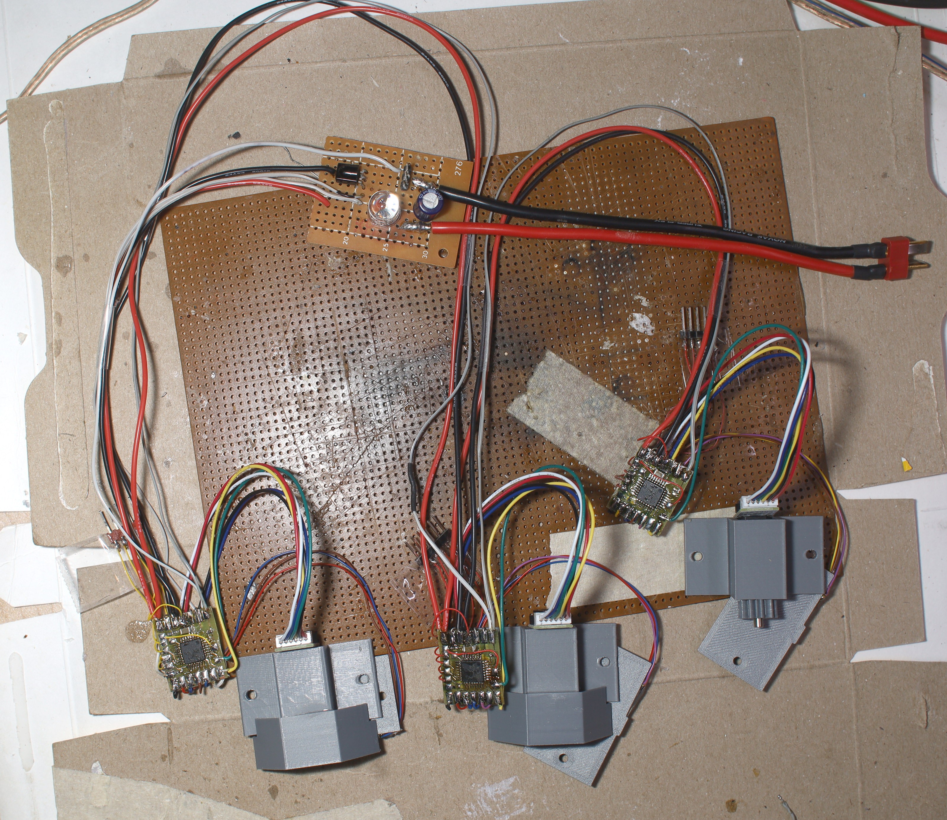
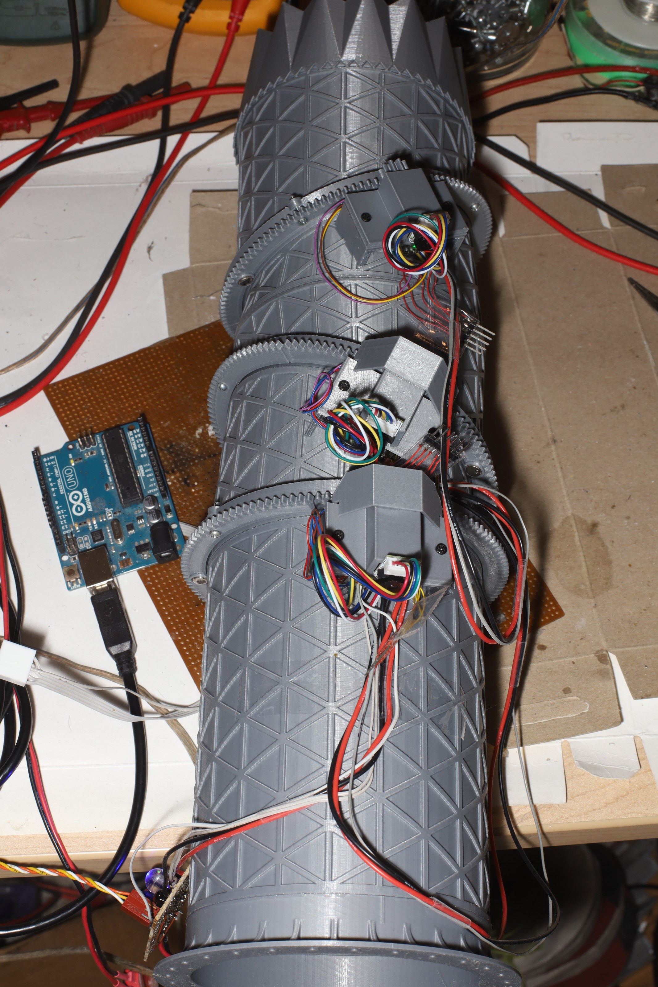
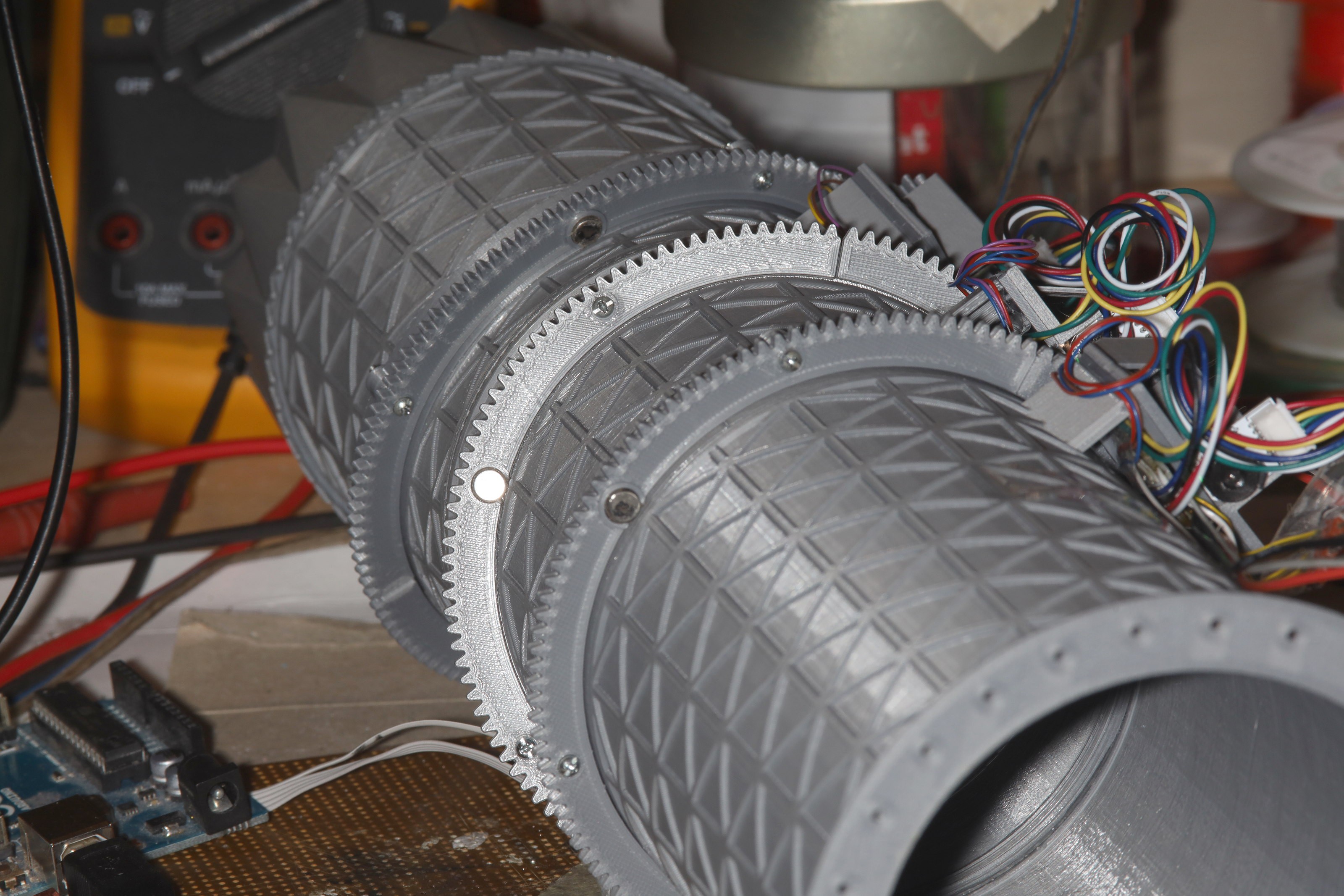
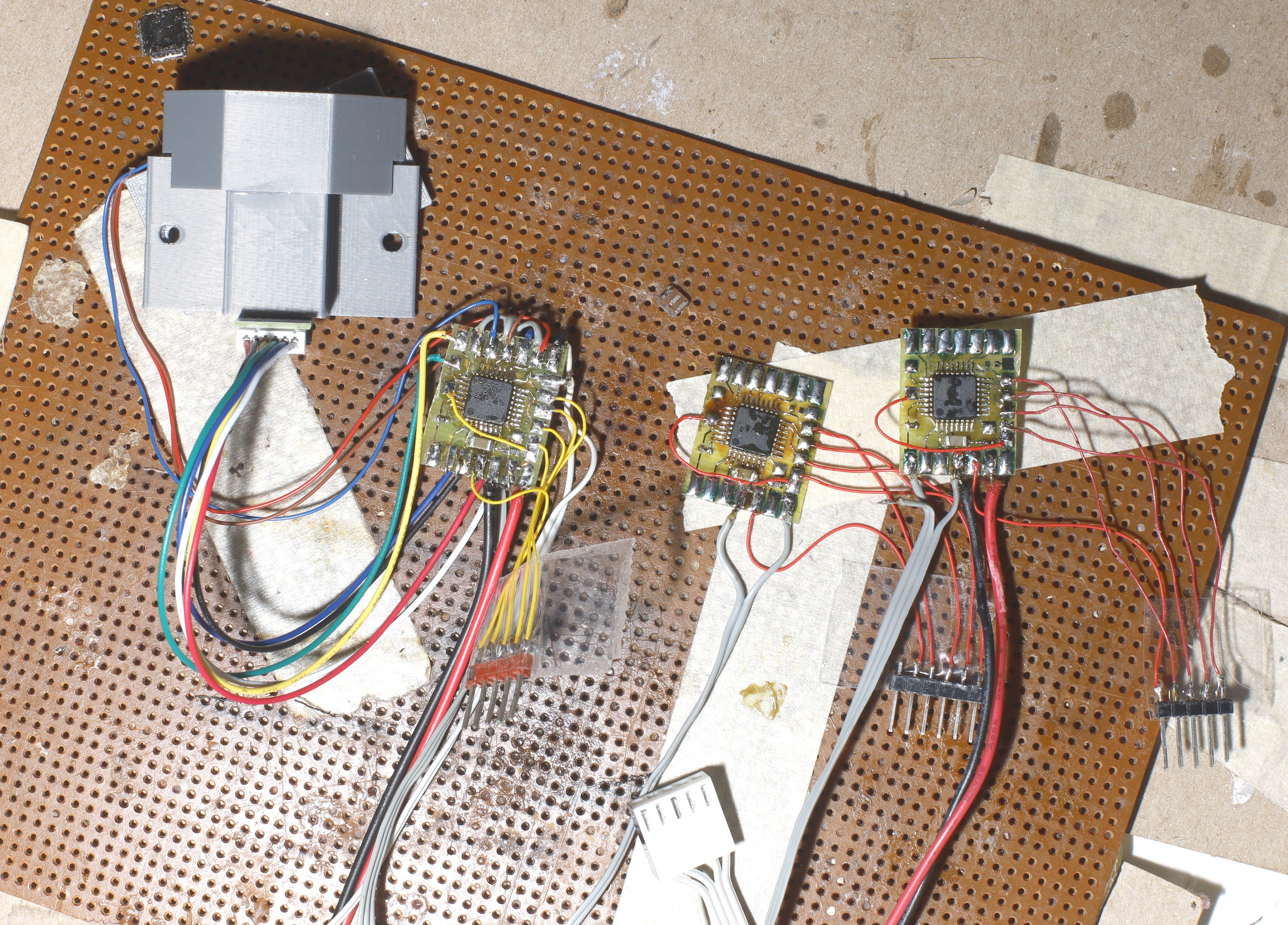
Motor boards all hooked up. User interface board hooked up. Wrong power connector. Lions use JST connectors for 5V & T connectors for 12V. Noted the 2020 revision of the H bridge had a green LED while the 2022 revision has a red LED & bigger vias. All 3 encoders have green LED's, so it's kind of an xmas tree.
The control boards were scotched in to allow future removal of the programming headers.
A bit of sandwiching got them all in.
There was a case of too much motor shroud snagging the cables.
The 2nd motor shroud has so far proven unnecessary, so it hasn't been shaved down. So far, there hasn't been any issue sharing the motor & logic power lines.
The single wire UART scheme worked. The maximum update rate ended up 20Hz per motor. The tricky bit is fitting debug statements between the control packets. Instead of a terminal program, it uses monitor.c. monitor.c filters out the control packets. It still needs to buffer the debug statements separately from the control packets & send fragments of the debug statements between the control packets.
The IR scheme is horrendous since it requires delaying if it misses a code. It needs to go back to an algorithm which continually checks every byte against every code. When the motors are disarmed, the remote control directly controls the motors with the arrow buttons. There are cases where motors get stuck on after the remote control stops transmitting. There's also crosstalk between the 2 nozzles in the room.
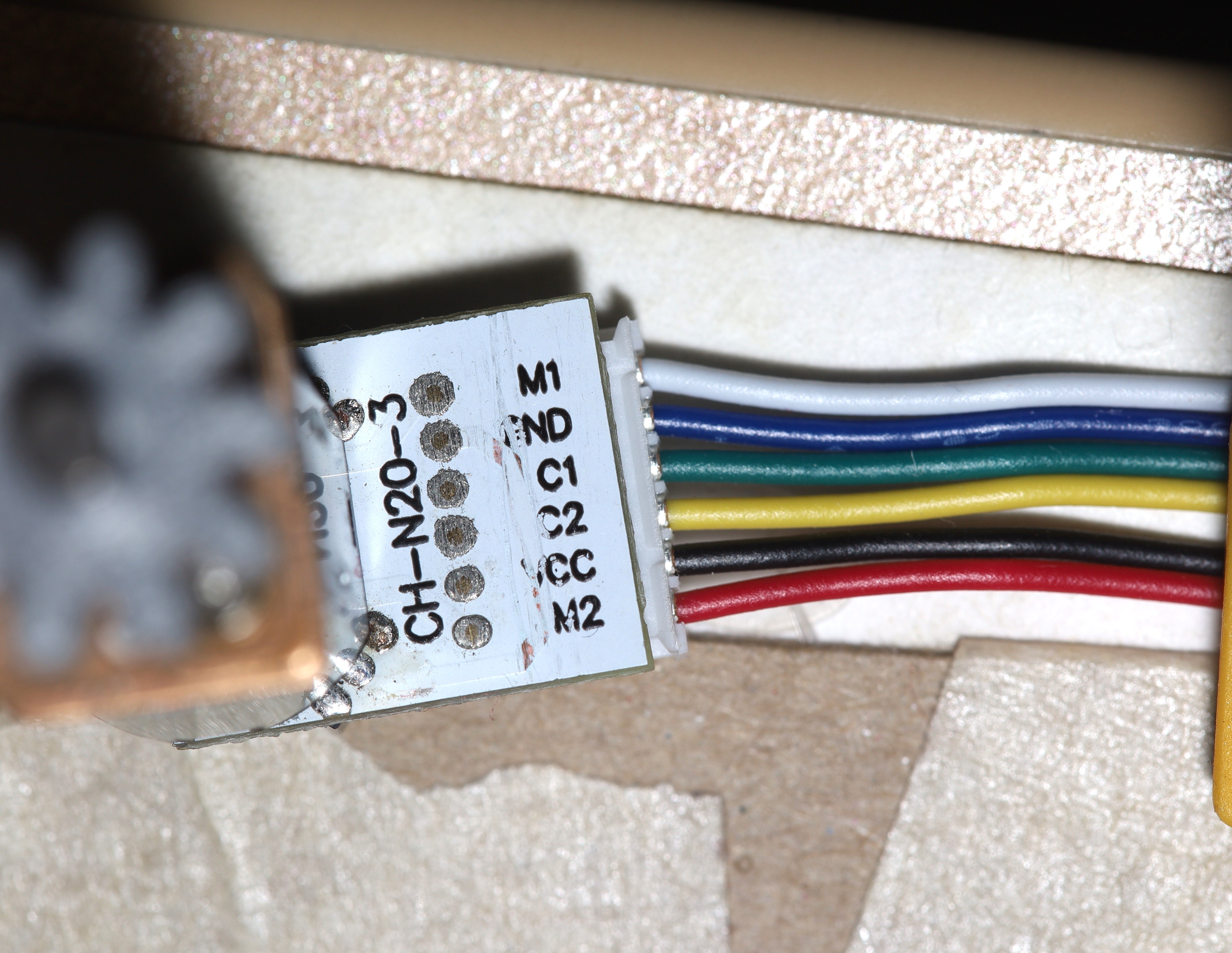
Noted the blue is Vcc & the black is GND for the motor encoder. Reverse the polarity & you get to order new hall effect sensors on the slow boat from China with $10 shipping. The encoder board is soldered onto the motor terminals.
The brain board was just a bundle of wires with a small chip inside. The leading theory was to use lots of excess wire & shorten it over time. A certain amount of excess wire is required to access the boards.
Still insisting on using up all the atmegas, an attempt to recycle some more Atmega8's from dead ESC's resulted in a dead uart transmit pin. It showed a very weak ability to go low. It couldn't go low at all with the receive pin pulled up & was very slow with receive low. Maybe it was damaged over years of driving.
The recycling process also required soldering on a crystal to all of the scavenged atmega's to change the fuse bits. Some of the new atmega328's from 10 years ago also required a crystal to accept a 1st program. Noted they didn't require loading capacitors. Must remember to try that for the bricked ones & put in pads for soldering a crystal.
With a week burned on trying to reuse atmegas, the decision was made to put the last of the new atmega328's in all of them. The next step is connecting the final wiring outside the nozzle, using lengths from the 1st nozzle, then testing all the protocols, motors & signals outside the nozzle. Another idea is making a 4th board for a debugging output, IR receiver, & LED. That would reduce the number of power rail connections on the brain board.
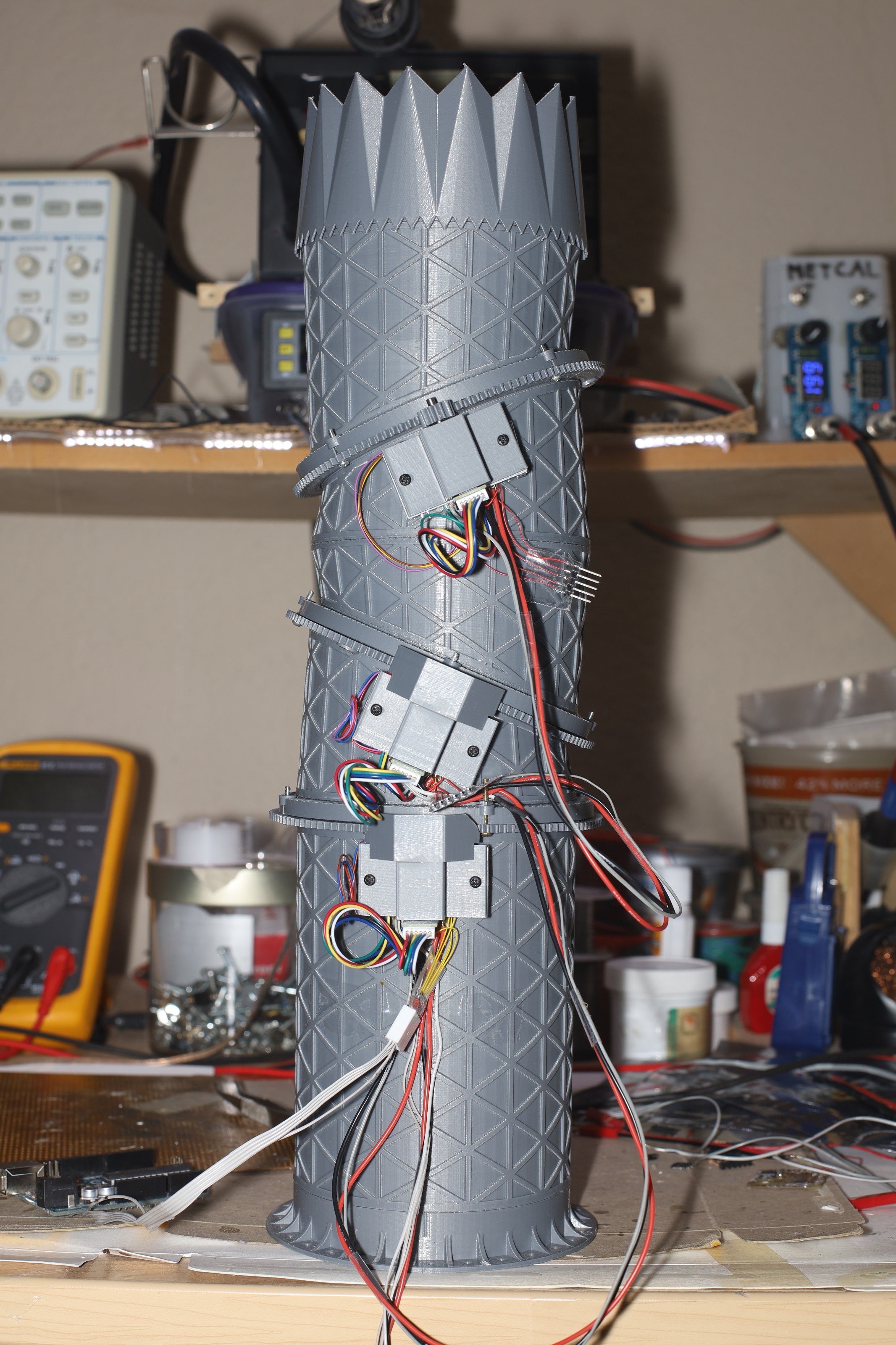
Staring at it for a while, it became clear that the most efficient board placement was not under the motors. The boards could be on the longest part of the tube segments with wires going sideways to the motors. The motor mounts could be narrower. The boards could be hot glued on. 2 more standoffs could be modeled into the tubes for a board platform.
The pinion gears slide too easily off the motor shafts. There could be side ridges to keep the pinions in place.
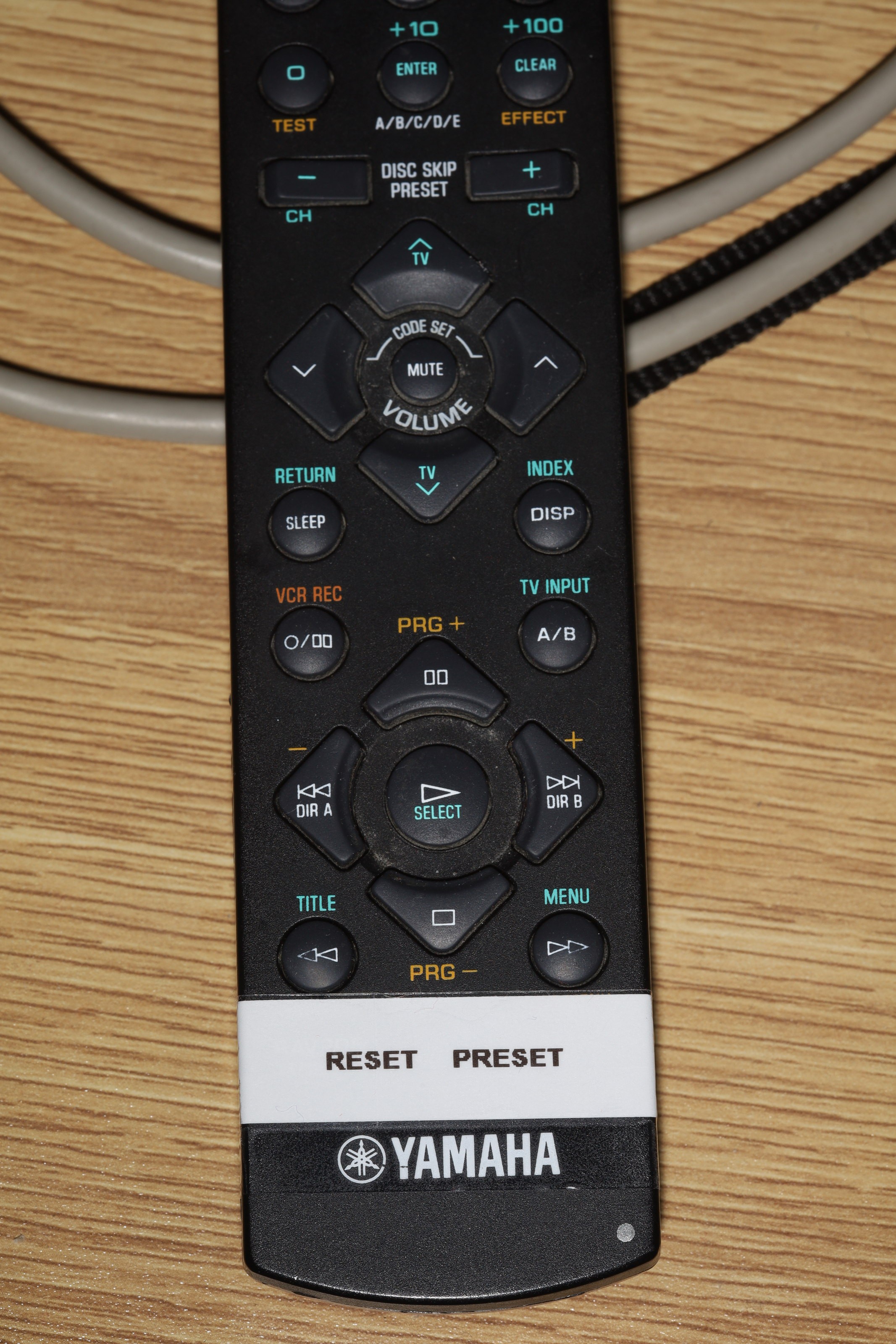
The 22 year old stereo remote control is showing signs of old age. The buttons are fading & have to be pressed a lot harder. The stereo lasted 10 years before its relays went out. Its remote lasted 22 years.


 Matthias Hasenfus
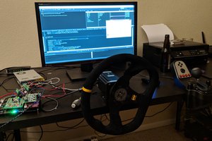
 John Taylor
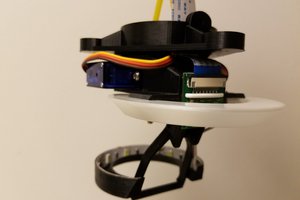
 Daren Schwenke