 mit41301
80C32/8052AH-BASIC single-board computer
The above diagram shows a minimum amount of hardware required to support the 80C52-BASIC chip. Small systems can be constructed with only an address latch, 1K byte of external memory, and the appropriate serial port drivers. With the addition of a transistor, a gate, and a few passive components, BASIC-52 can program EPROM/EEPROMs directly. Both standard and fast programming algorithms are supported.
THINGS REQUIRED:
- FPGA BOARD
- HDL based 8052 softcore
- latest BASIC-52 firmware
- SDCC or Keil assembler/compiler/IDE
- UART TTL-USB board
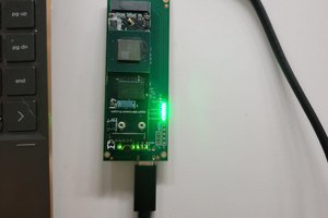
FPGA BOARD
We can go with small form factor and low cost FPGA boards for easy and affordable implementation. Tested with MAX1000 board and STEPFPGA-MAX10 board. Both the boards are 8k Logic Elements.
MAX1000 comes with 10M08SAU169C8G FPGA device
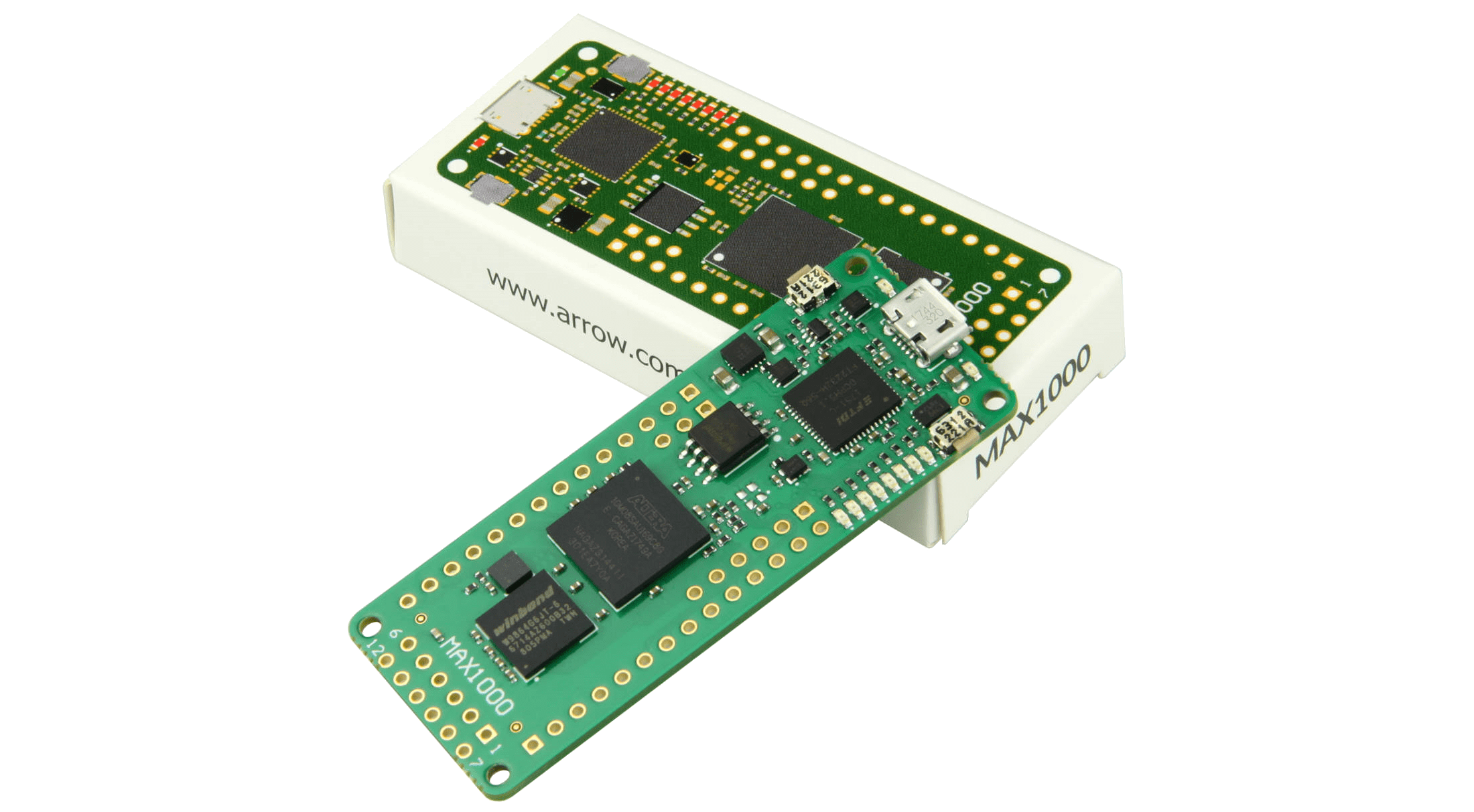
STEPFPGA-MAX10 comes with 10M08SAM153C8G FPGA device
Both the boards are based on Intel MAX10 FPGA. Both the boards have inbuilt JTAG configuration support. There is no external FLASH memory required to store the configuration and user program. We can use SOF for SRAM based configuration and POF for permanent FLASH storage.
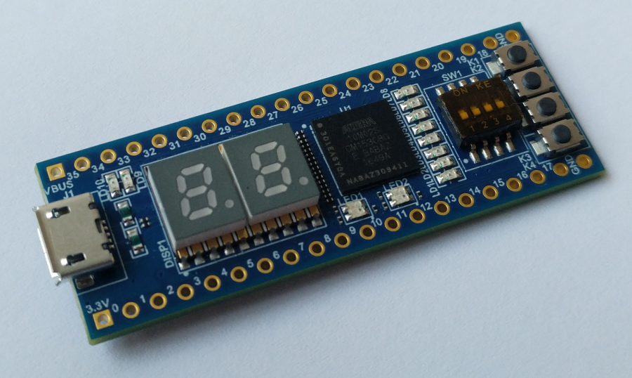
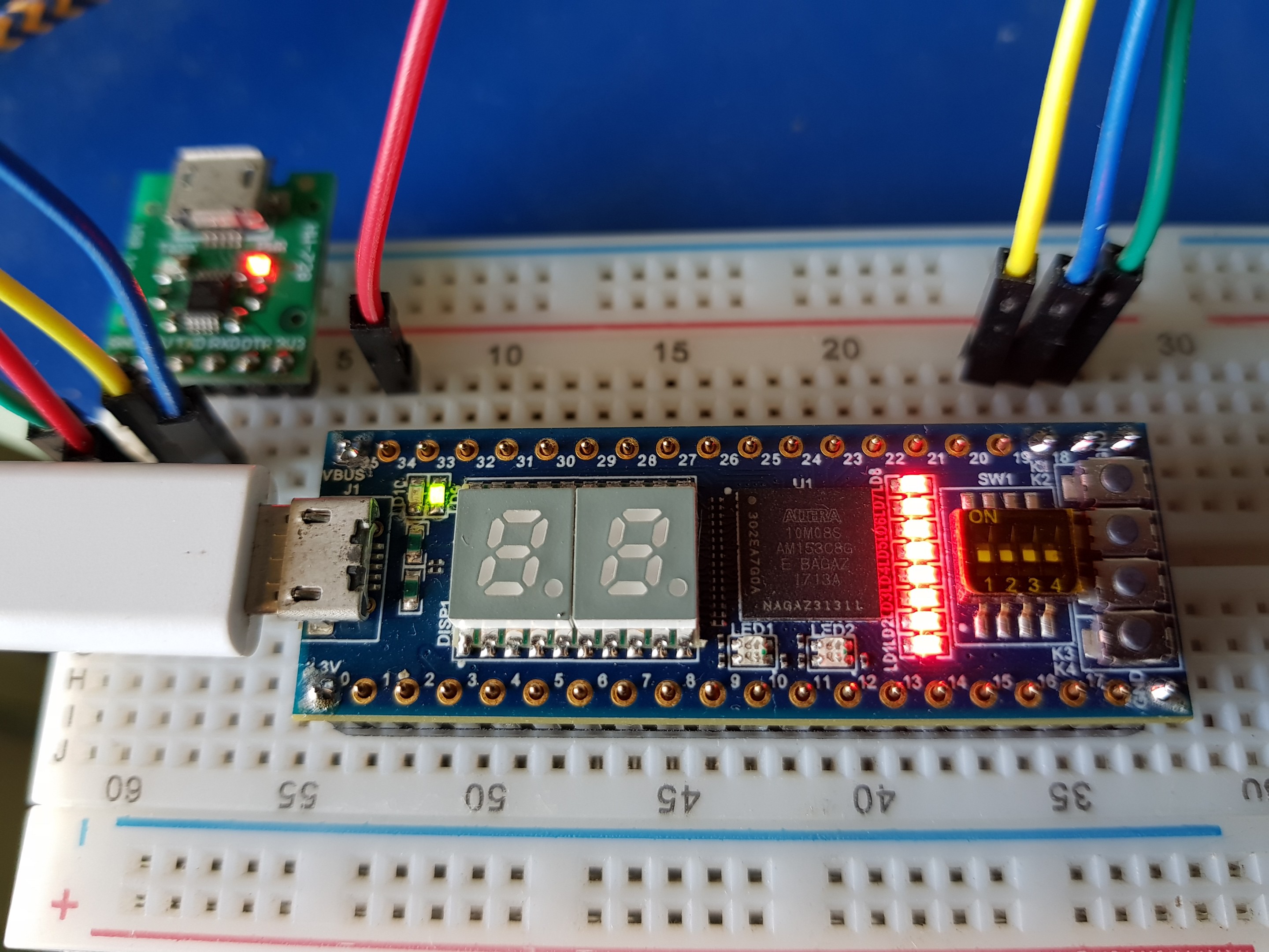
STEPFPGA-MAX10 Overview
- Intel MAX10 FPGA: 10M02SCM153C8G/10M08SCM153C8G/10M08SAM153C8G
- On board USB Blaster programming circuit
- 2-character 7-segment display
- Two RGB LEDs
- Four switches
- Four push buttons
- Eight user LEDs
- Power from MicroUSB connector
- 40 pins DIP connector with 36 User I/Os
The above FPGA board available with 3 different device variants. The tests were performed using 10M08SAM153C8G. This board is very small and compact size comes in DIP-40 size with 600 mils wide.
STEPFPGA-MAX10 pin map
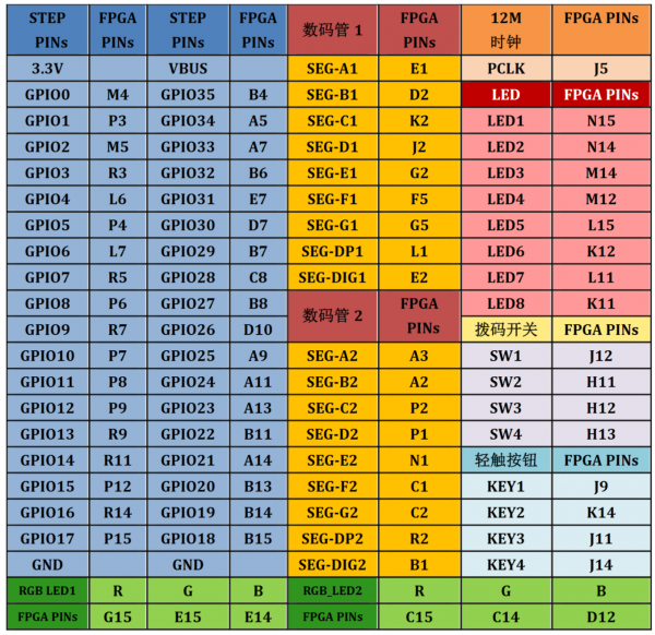
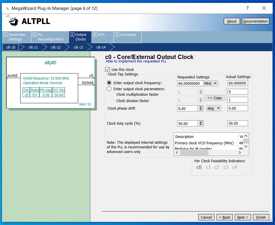
The system clock oscillator is 12MHz. We can run the system as it is or through inbuilt PLL. We can go upto 60MHz clock for C8 speed grade of the MAX10 FPGA
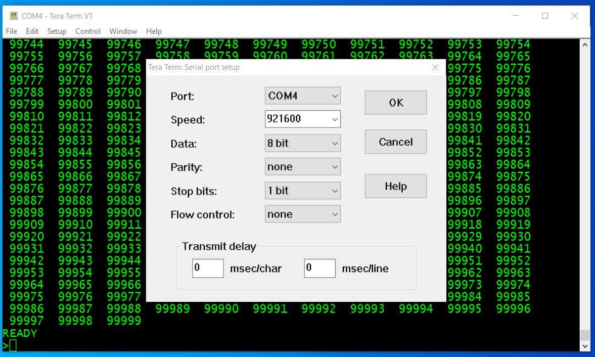
Similarly the serial output was tested upto 921600 baud rate!
T8052 softcore
There are many free HDL softcore available both in VHDL and Verilog. We will go with T51 core and can be downloaded from here. Apart from the 8052 controller we have to implement 8k ROM required for BASIC-52 and 4k RAM for program and variable storage.
We can load the BASIC-52 into ROM using VHDL file or intel HEX file format. Loading HEX file is much easier than converting the HEX file into VHDL.
BASIC-52 FIRMWARE
The latest available firmware version V1.31. Both source code and HEX output file are available. We need to include the path of the HEX file in the init_file for the ROM implementation so that the HEX file will be automatically loaded into the 8k ROM.
We can also have LED blinky project and HEX file for initial testing of the core before loading the BASIC-52 into ROM.
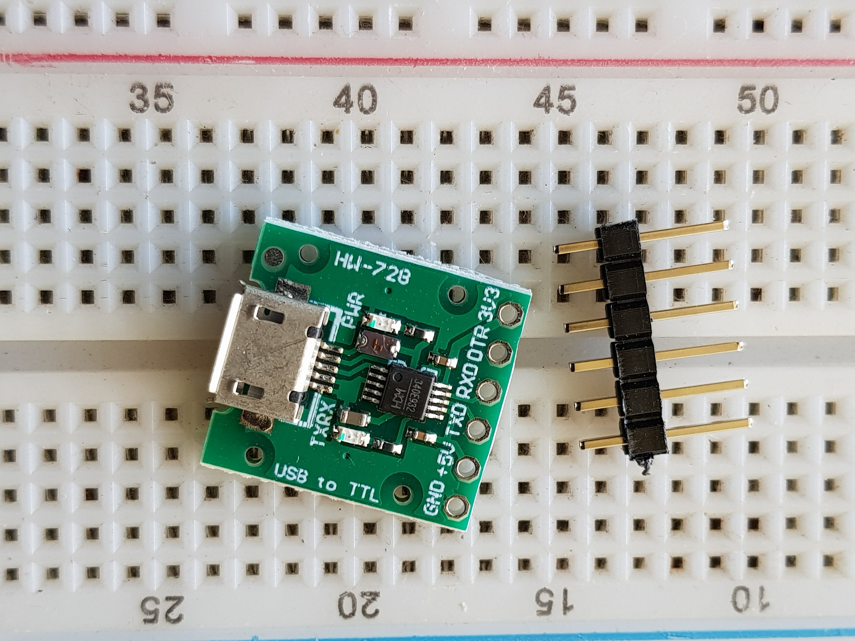
USB to UART TTL Converter
Any standard converter supporting 3.3V level is sufficient. We will be using Tx, Rx and GND signals. If we want to power up the SBC from USB to TTL converter board, then we can make use of +5V from the converter board. By using this we eliminate additional cable.
BOOK REFERENCE
The Microcontroller Idea Book: Circuits, Programs, & Applications featuring the 8052-BASIC Microcontroller by Jan Axelson. Now available as a free PDF.
CONCLUSION
Tested the 8052 BASIC-52 SBC with 60MHz clock and serial baud of 921600. Works without any issues.
The same concept can be extended to other family of processors or controllers.
 Sean Blakley
 SdtElectronics
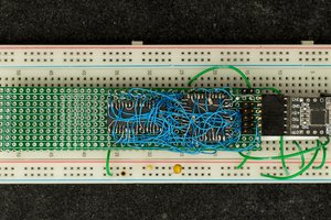
 Plasmode
 Parker
I dont know how to put this, im not well traversed in electro-enginereing. BUT. Im a scrapper. And I recently came across a lot of what you mess around with.
I have an CXM52 singleboard computer fra Intel, designed by Henrik Enig dated 0707 - 87. Additionally, theres an UV eraser, device programmer and what not. Theres still a few cable left, as well as some "homewired" PCBs
Long story short; I have original hardware with loads of random EPROMs, some PROMs. I dont have any interest in it, (other than the scrap value), and It would be my pleassure to mail it if youre interested. I cant garantee theres all you need, but its obvious that the guy who dumped the stuff I have was dabbling in excactly the same as you do now. Onle he did it in the 80.. ish
I would in return appreciate if you can compensate the shipping and possibly lost income from the scrapped goldpins etc. I will not put a price on it, il leave that part 100 % up to you. Im not here for profit, I just came across this site when I searched google for some details.
I know this reply may seem a bit odd, but let me know if theres anything you need to know, if youre interested at all. Im afraid I alrdy scrapped one board, but as an "oldschool" component-source, then theres sill plenty of "juice".
And tbh, it would be a sad day to destroy what is (possibly) electronic history