 RobsonCouto
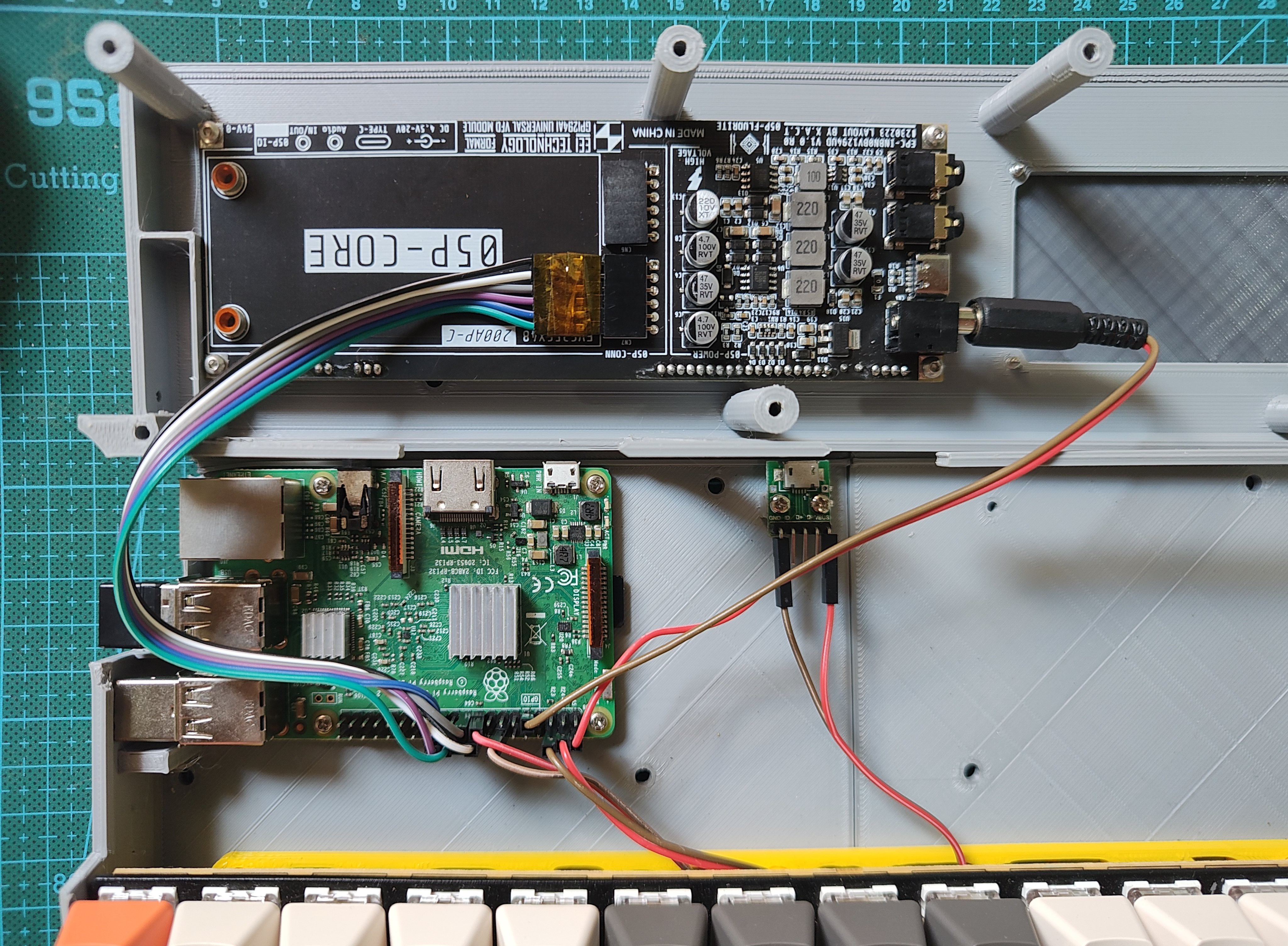
Why a raspberry pi 3?
A pi 4 would be better, but a 3 is what I had available.
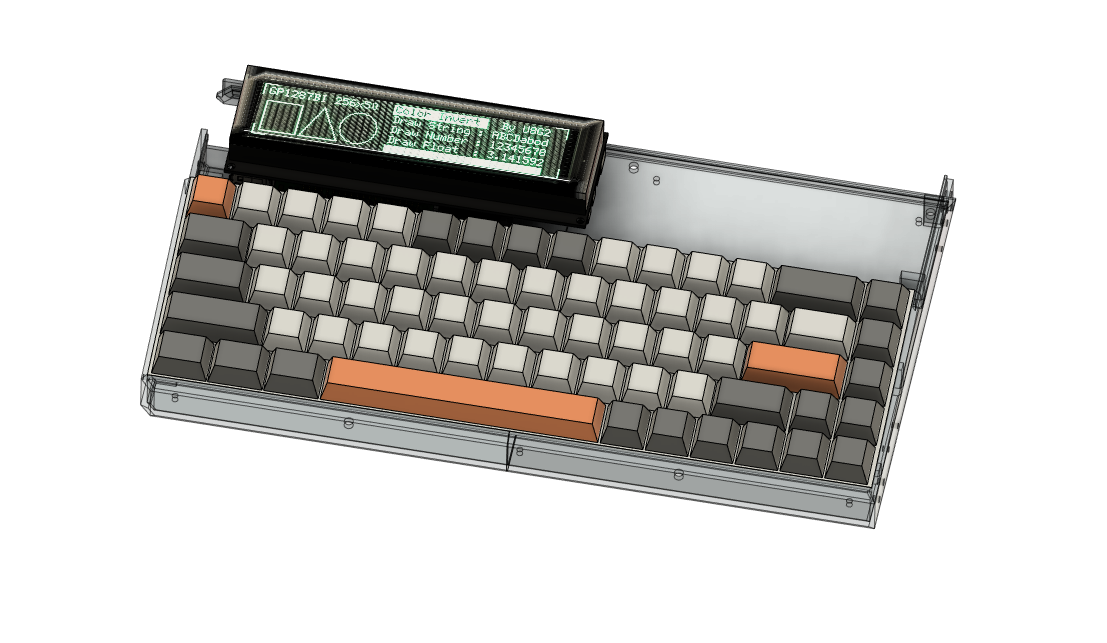
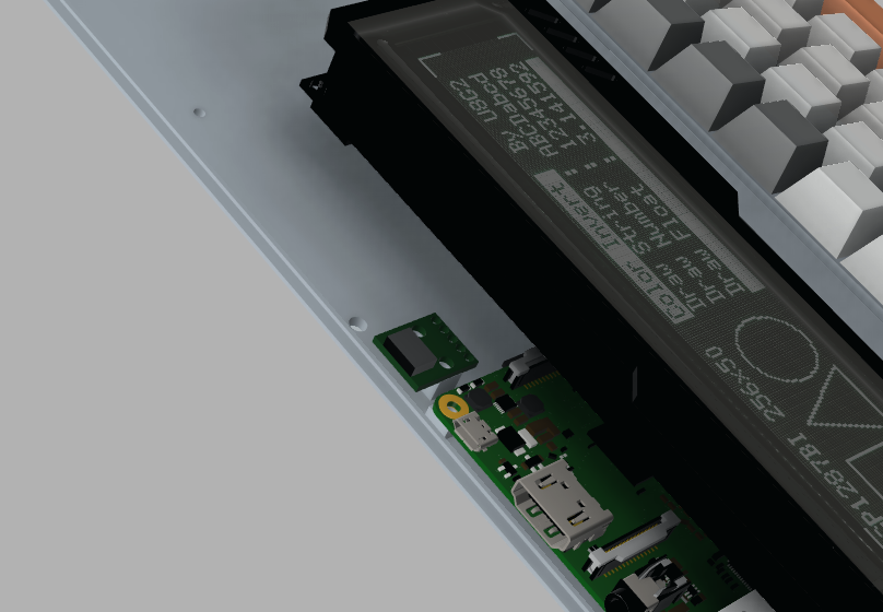
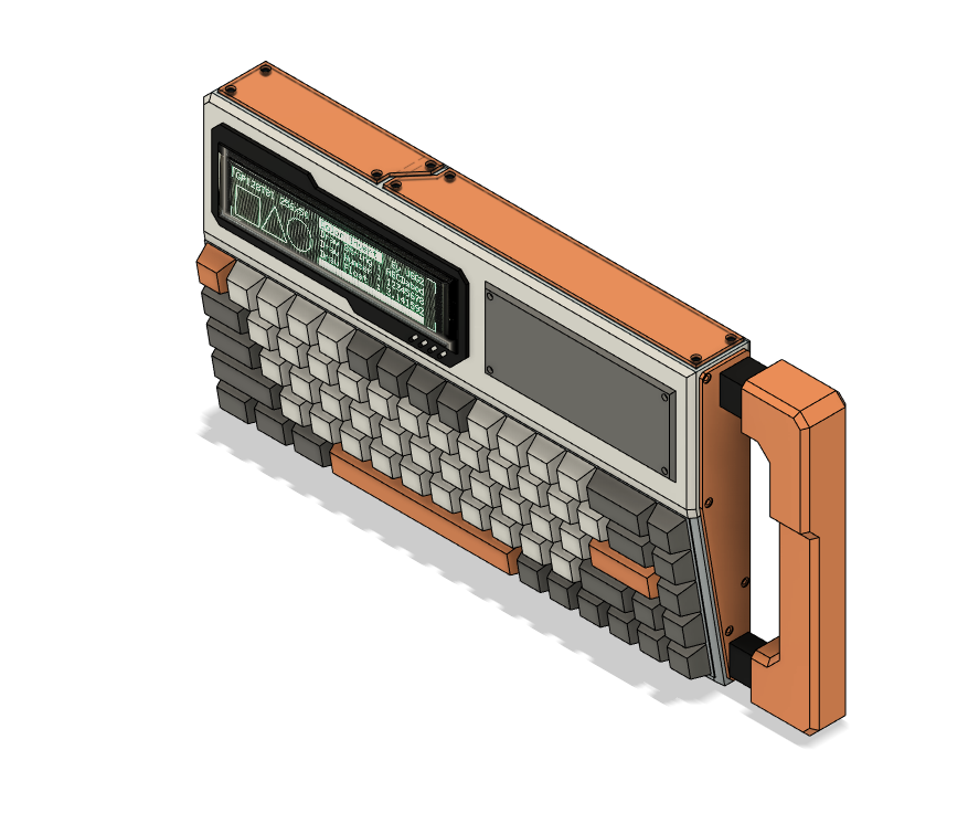
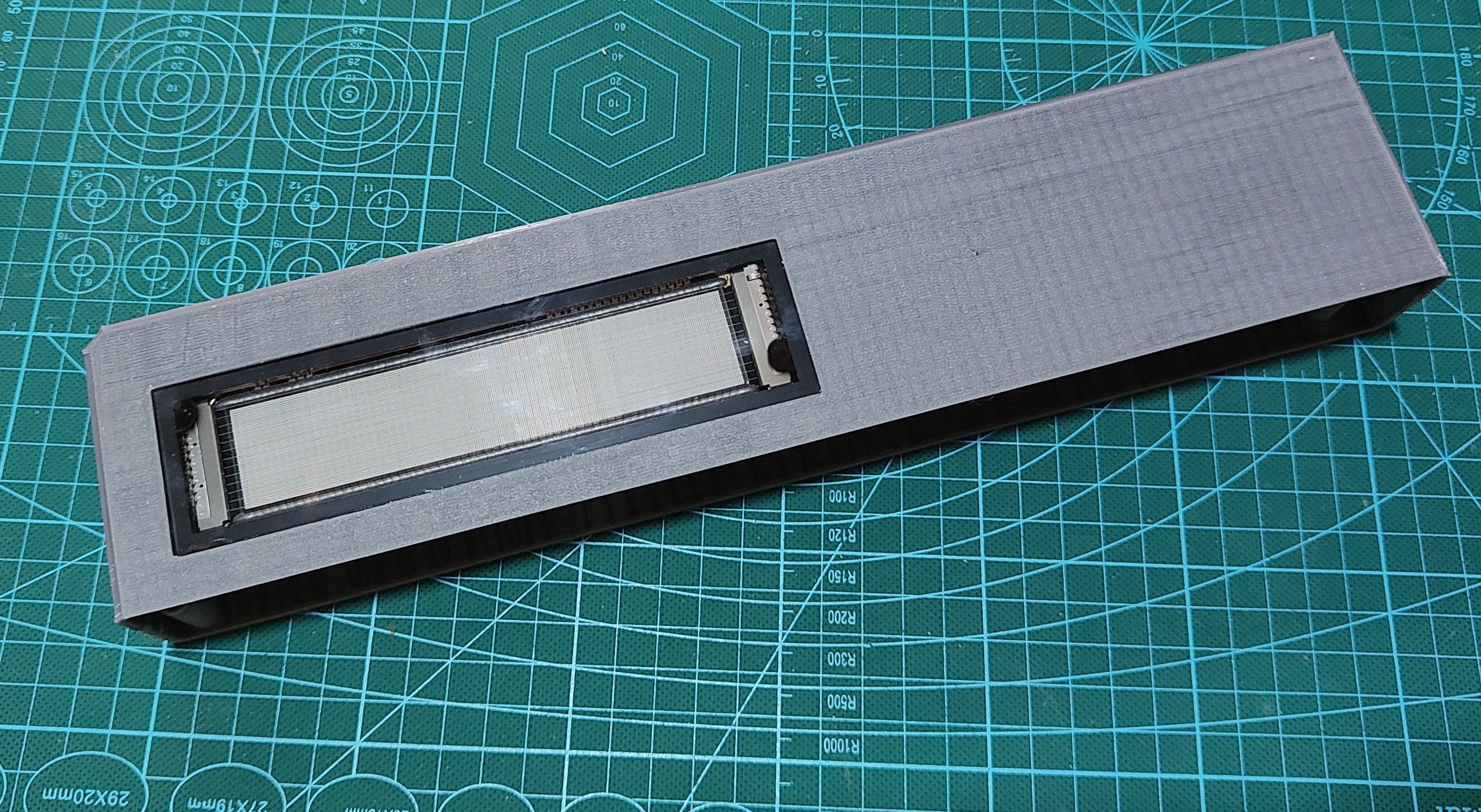
Why this display? Is not 256x48 a very low resolution?
I'm only using this display because it looks beautiful. But being honest, If I really needed a better resolution, I would use my laptop. I do hope that I can use my phone as a remote display, but with this project I'm trying to be an artist and a (kernel) hacker more than a user.
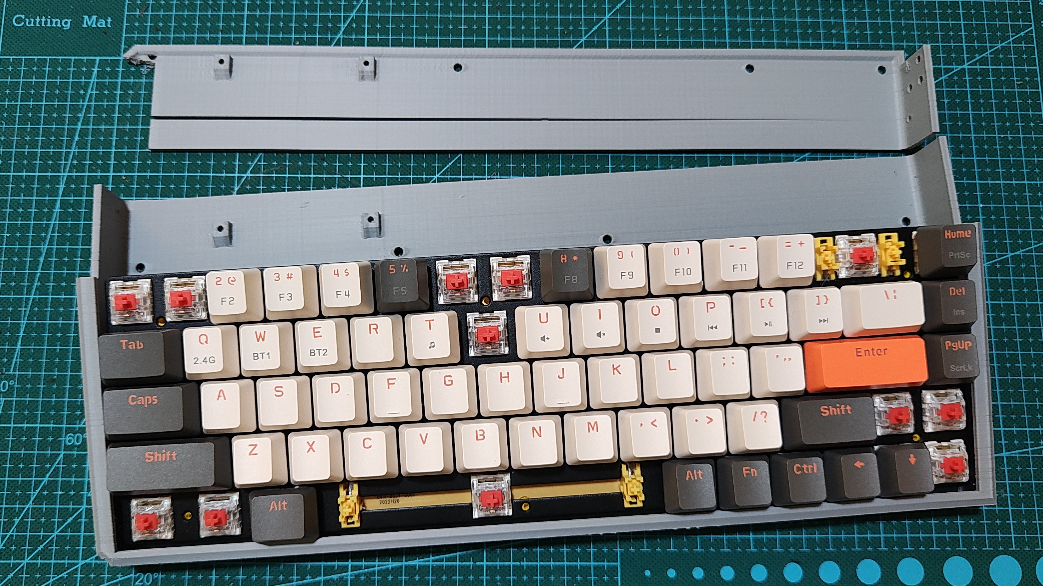
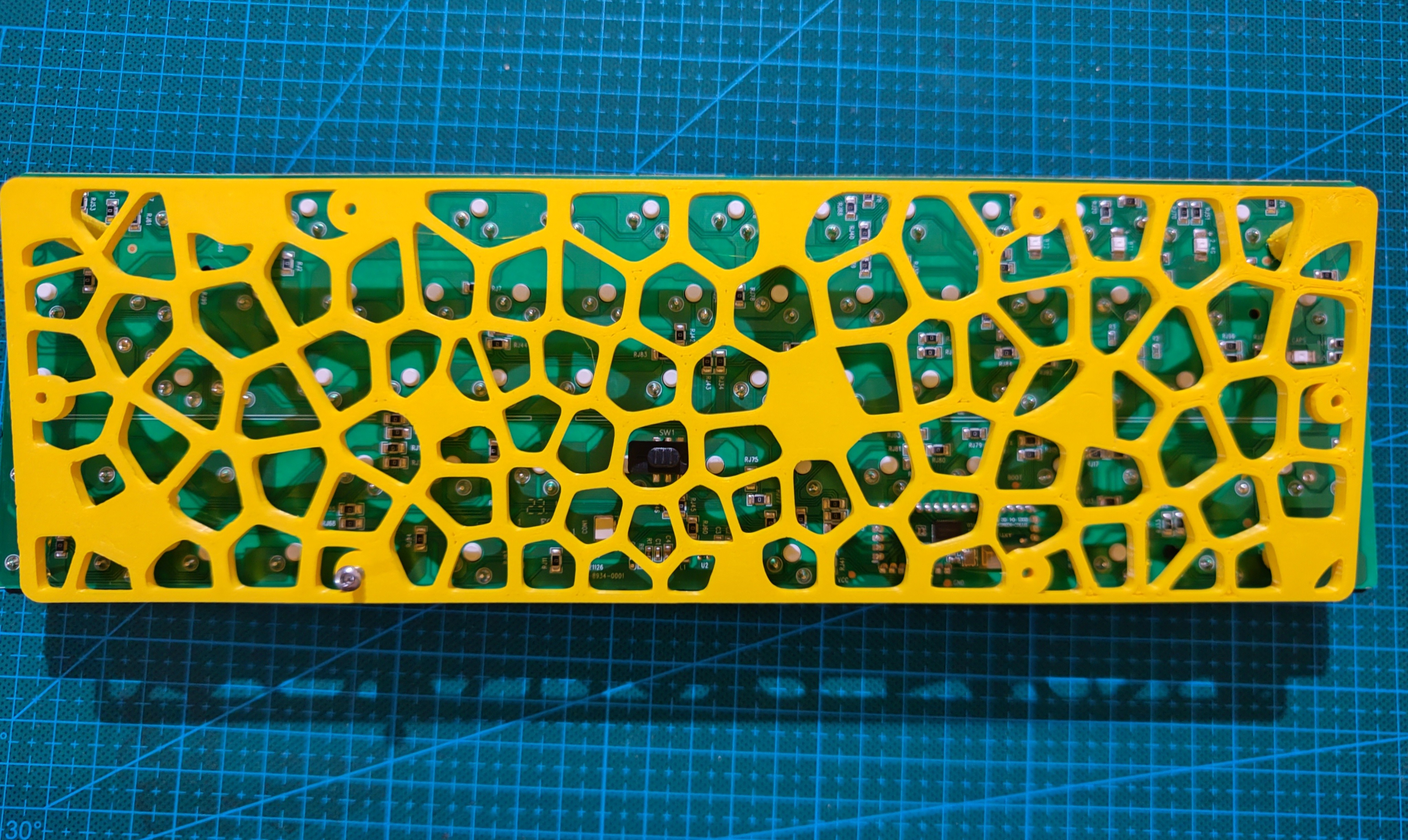
Which keyboard is this?
I got is on Ali, it's simply referred to as K68 and it is not backlit.

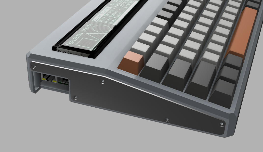
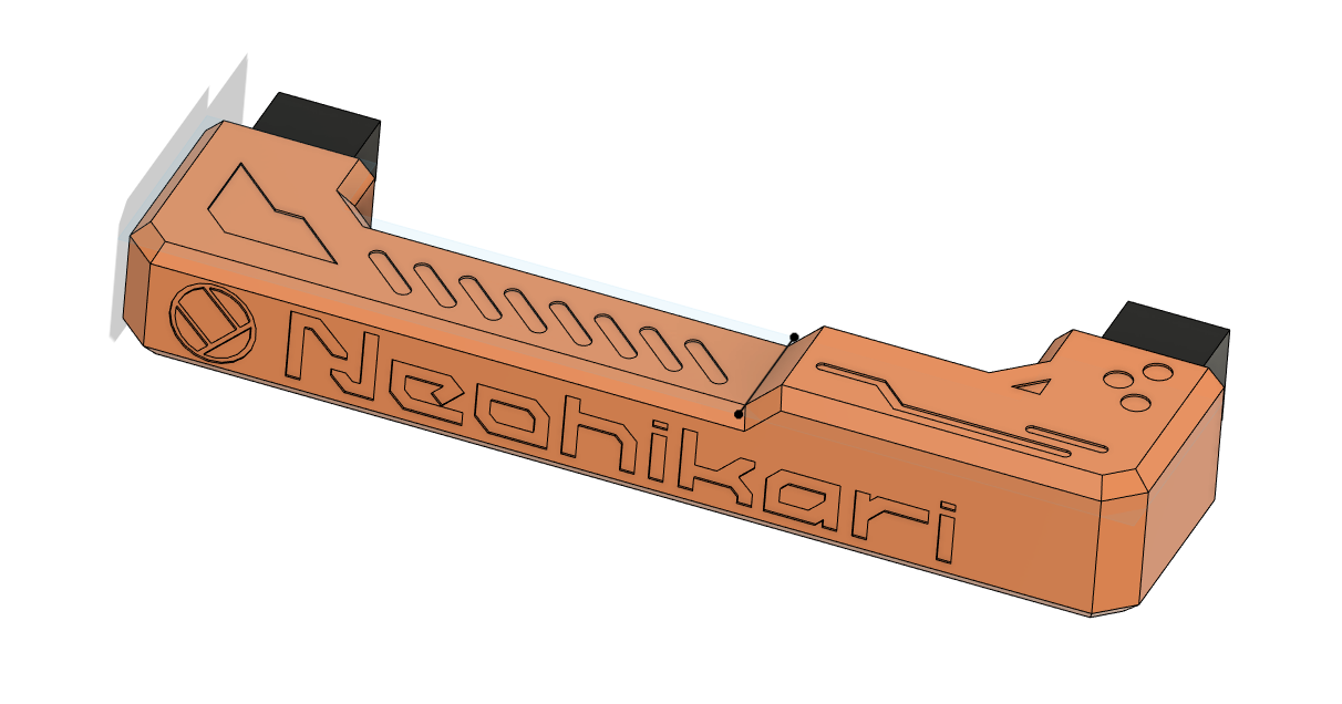 I've watched some videos on detailing, although not about cyberdecks, but still really useful tips for making props and models look hi-tech.
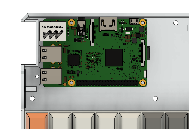
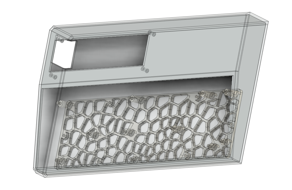
 I also took the opportunity to touch up the ethernet and USB ports cutout from the raspberry pi on the side of the deck and I'm so proud of that :)
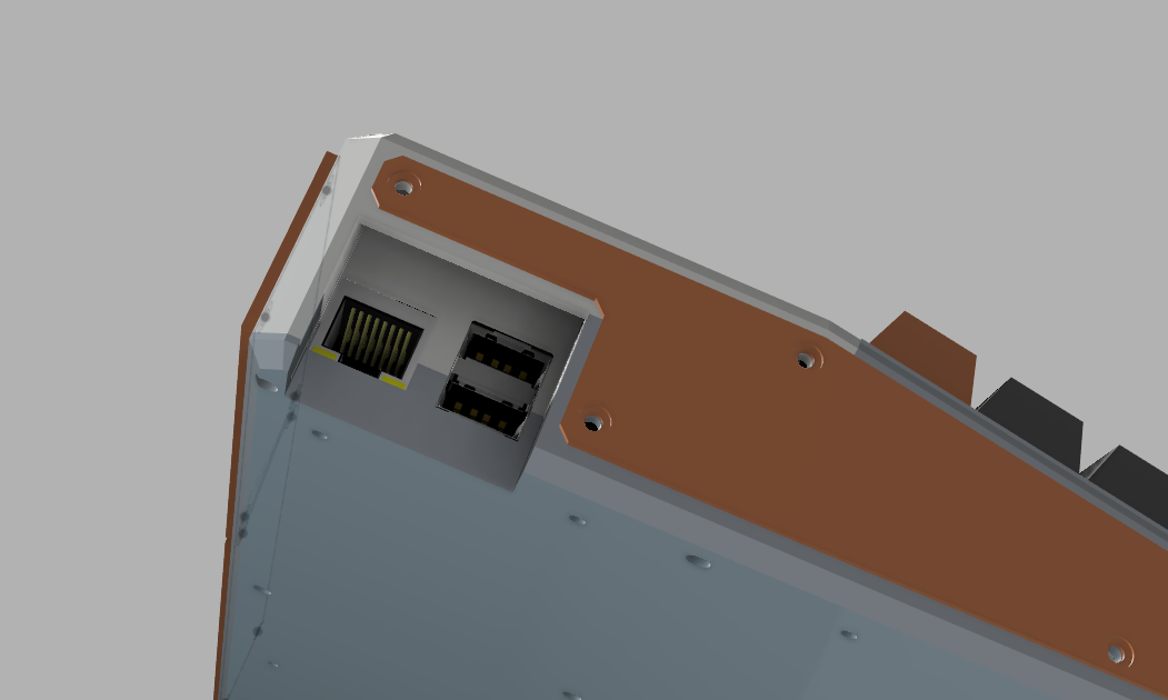
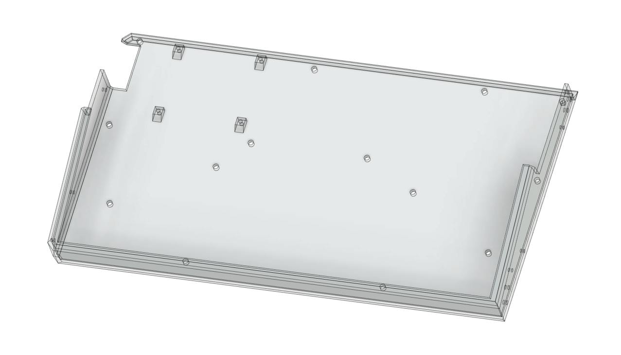
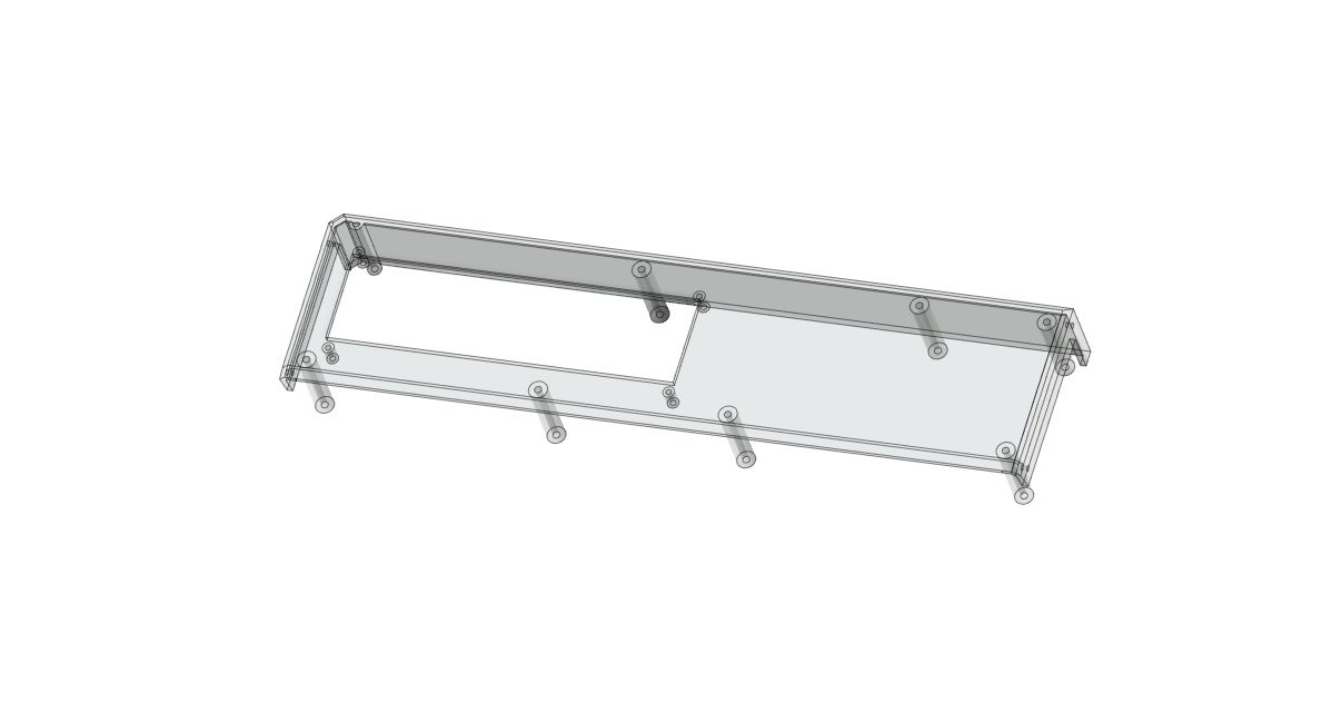
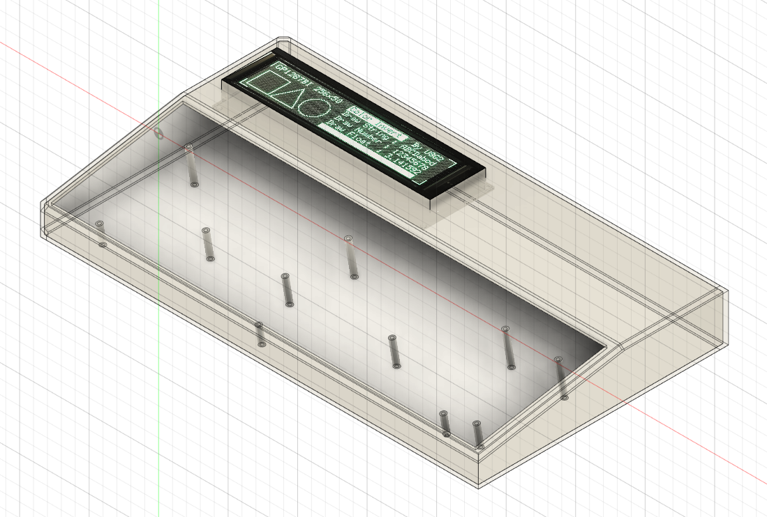
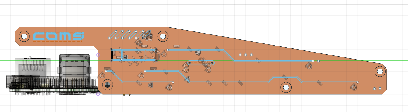
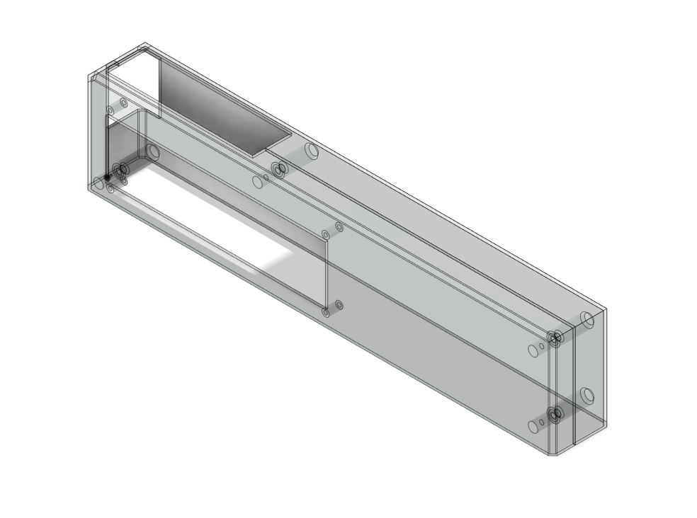
 The hardware seems to be correctly positioned and dimensioned, and that is a relief. This is my second time designing something in 3d, so that is why I'm taking this design-print-test approach.
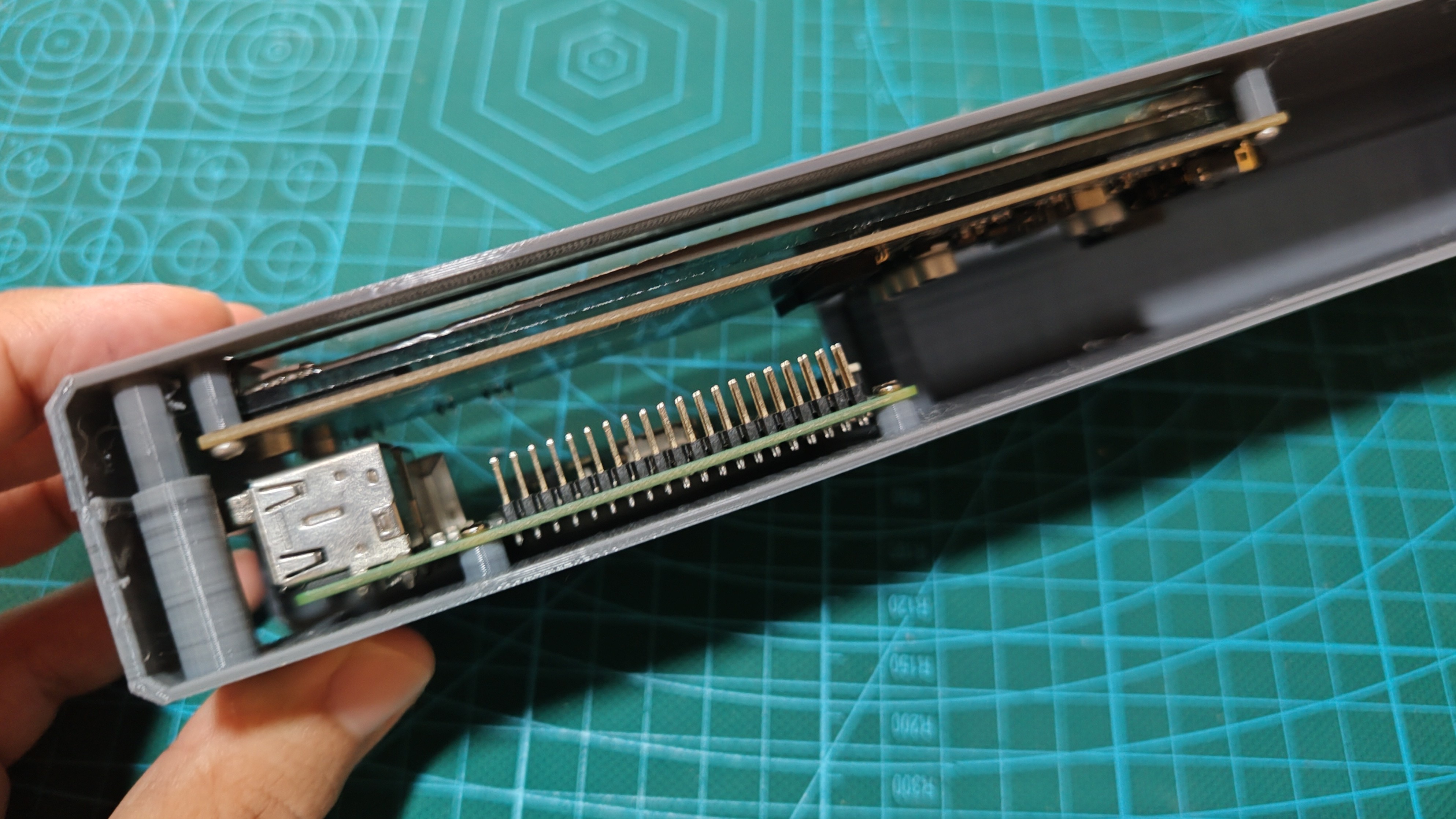


 Dan Jilek
 M.daSilva
 Leonard
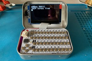
 Matthew Begg
the source code for the VFD,spi driver ,where to find?