 Andrea
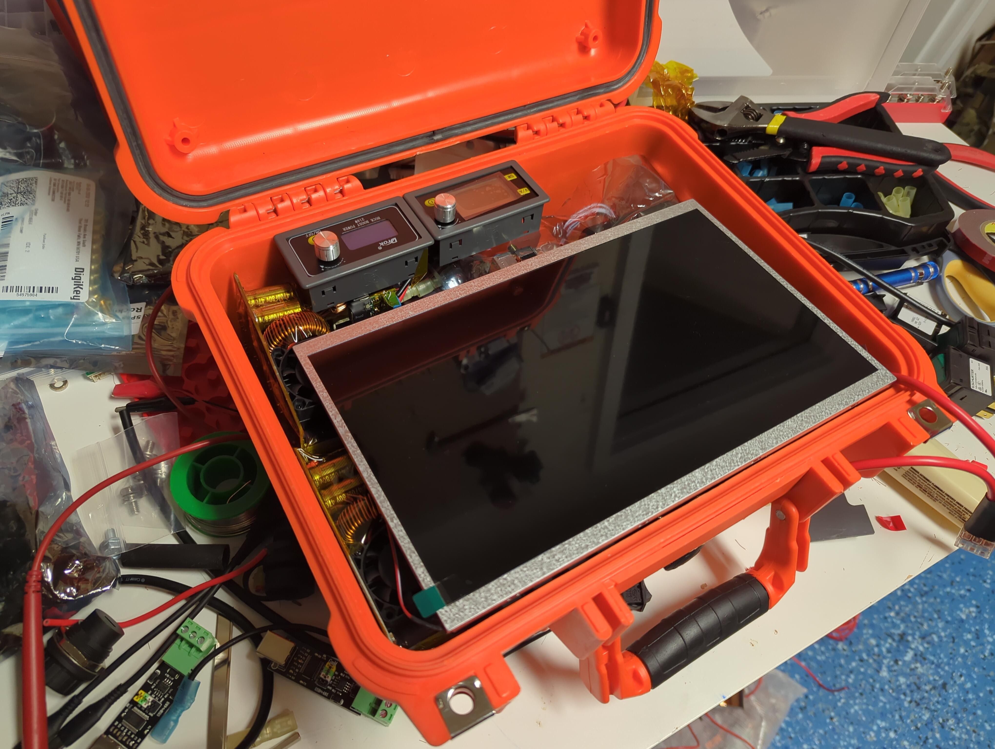
Power Supply
First the requirements:
| Device | Voltage | Load |
| PC | 12V | 200W Max (~30W at idle) |
| Kraken SDR | 12V/24V (USB) | 12W |
| Screen | 5V (USB) | 5W |
Over-provisioning to 300W at 12V means I should expect to draw less than 25A, and at 24V just 13A.
Since I want to be able to charge quickly, 25A at 24V is also an ideal charging amperage.
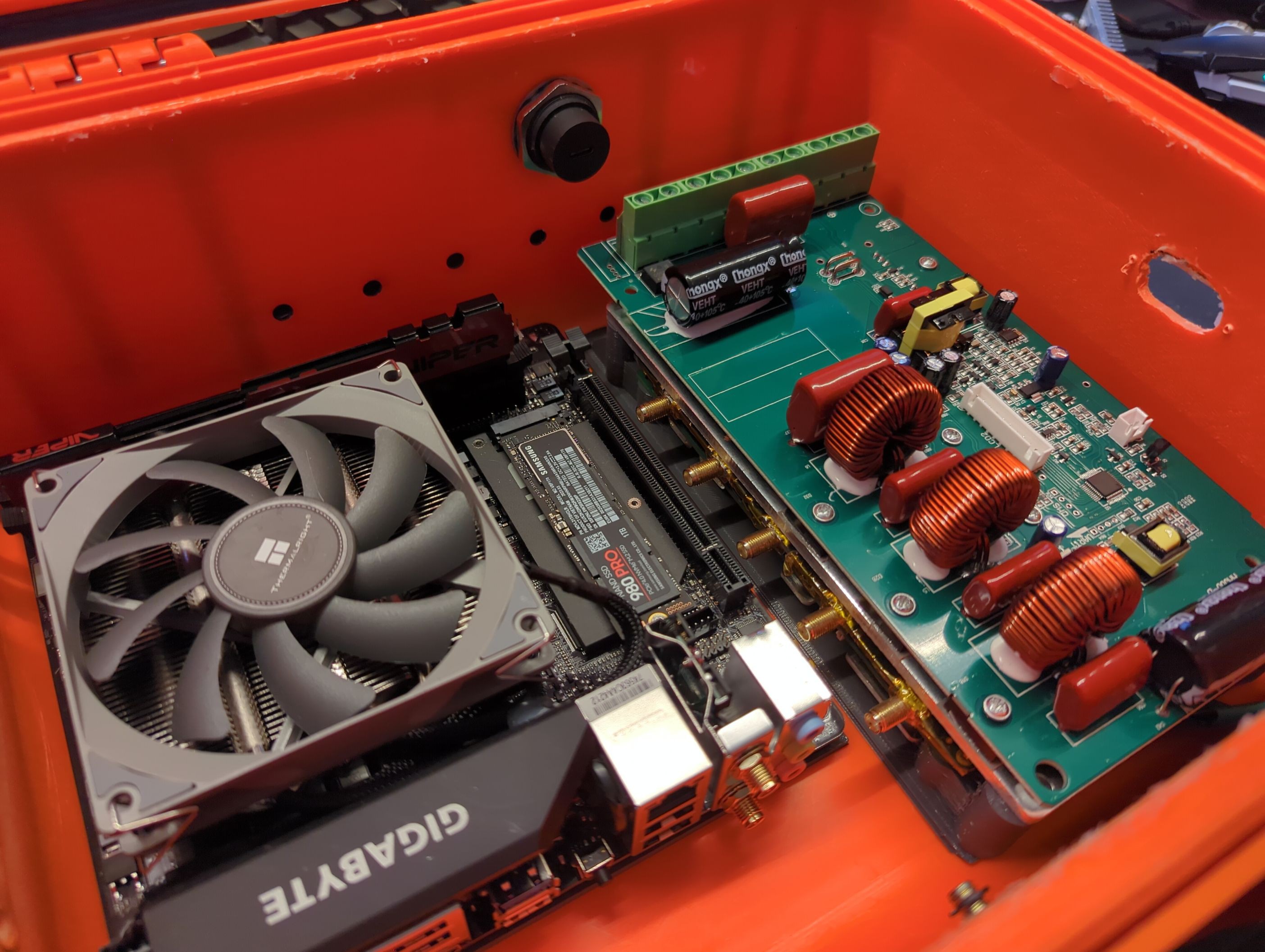
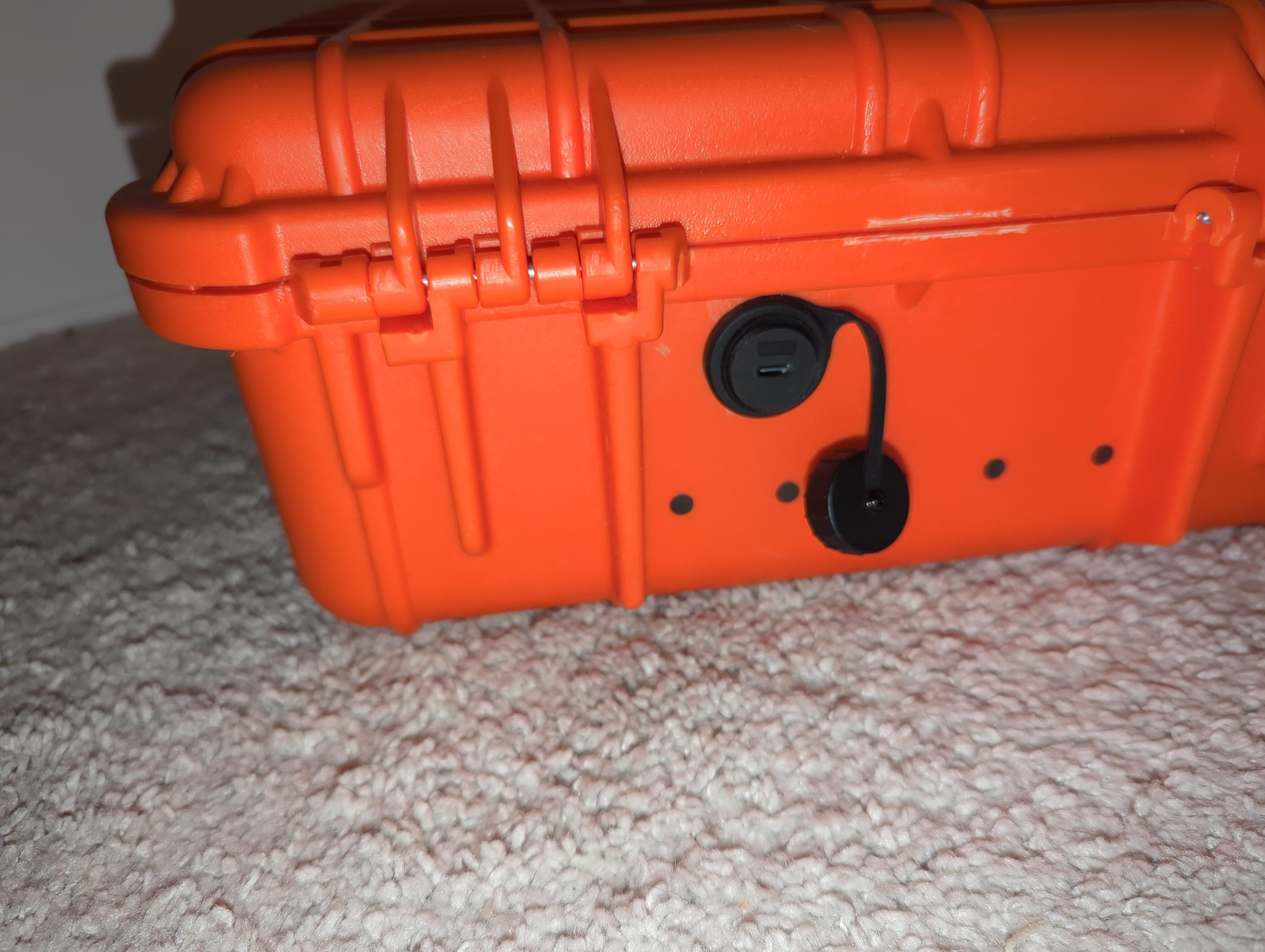
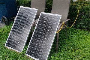
The PowMr 60A MPPT charge controller can handle this easily, but it's bulky and it can only buck not boost. My friend and I are working on a replacement for this which has both buck and boost capacity in a wide voltage range. The PowMr can at least handle a wide voltage input for charging, for a 24V system it's 37V-105V. Additionally it can accept this from both a standard DC source, or from solar panels with MPPT charging.
To round things out, two USB PD Decoys in series will result in a 40V source that can feed the controller, which means I can use all those spare phone chargers I have laying around.
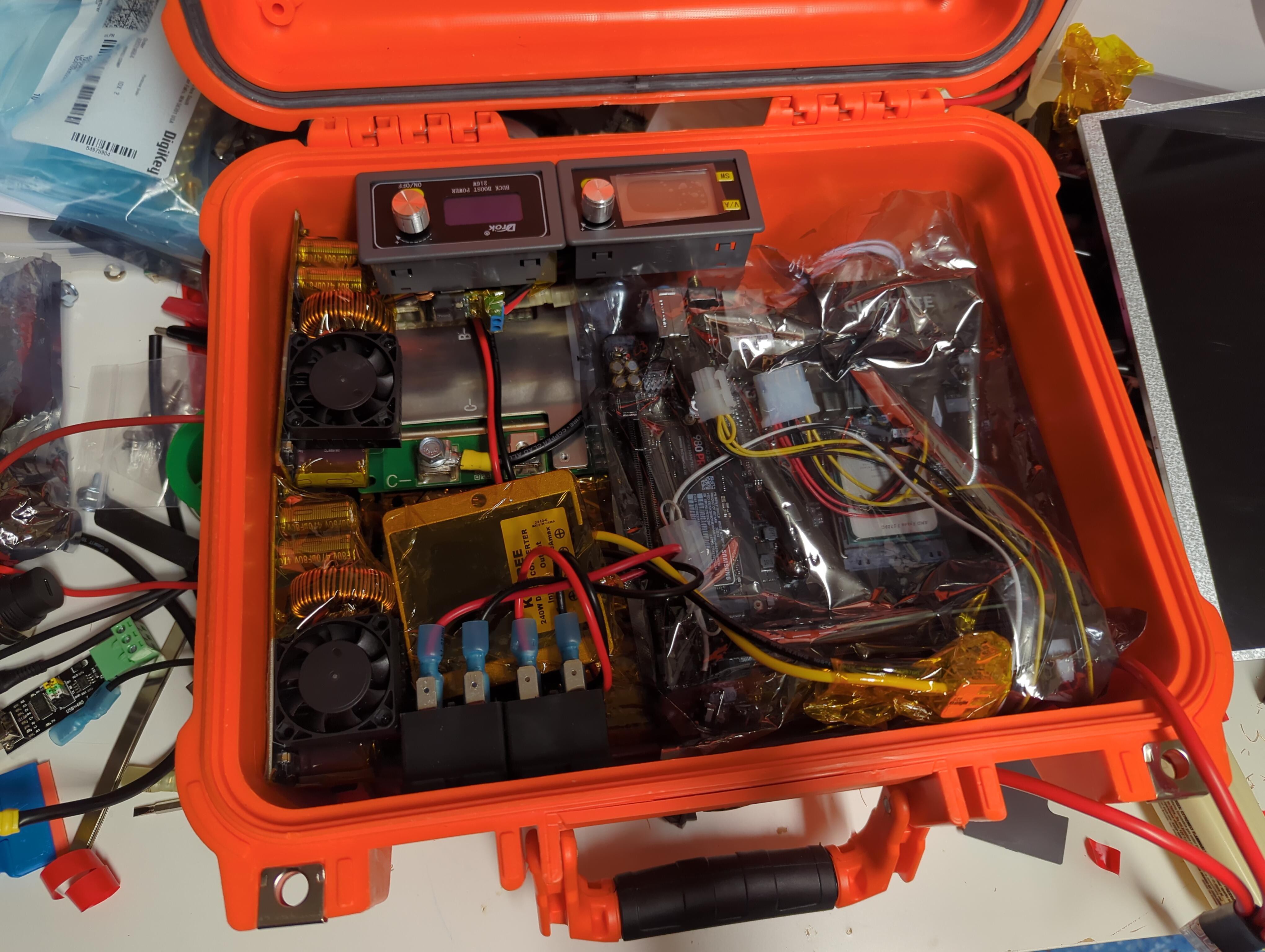
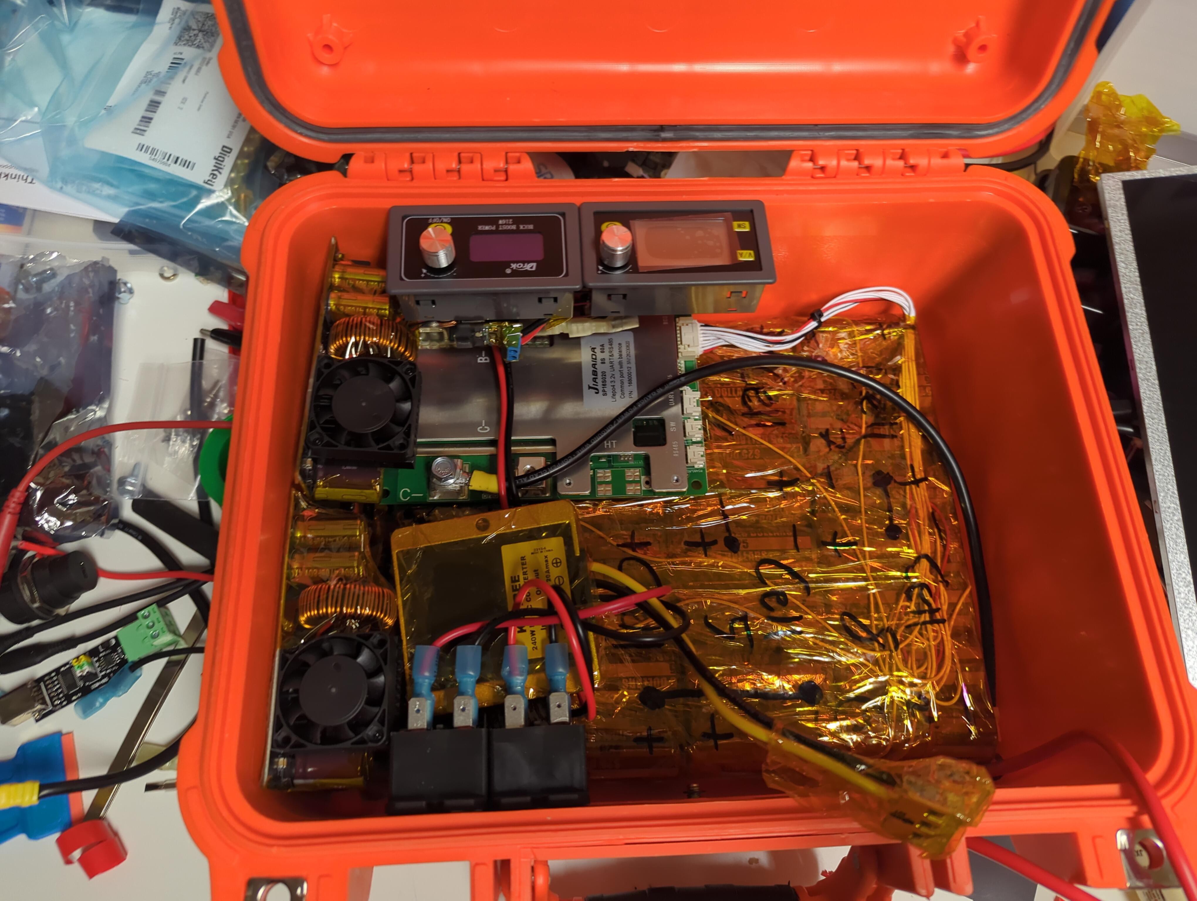
Power Storage
In order to support a higher charging amperage, 24v is just about the lowest voltage that seems reasonable. This gets us up over 550W which ensures I can always charge the battery at a good rate even under heavy load at the maximum provisioned 300W.
- Sony 26650 US26650ft
- When the cells are new they are 3000mah
- Nominal voltage: 3.2V
- Fully Charged Voltage: 3.65V
- Fully Discharged Voltage: 2.5V
- Max Continuous Discharge: 30A (10c)
- Max Continuous Charge: 6A (2c)
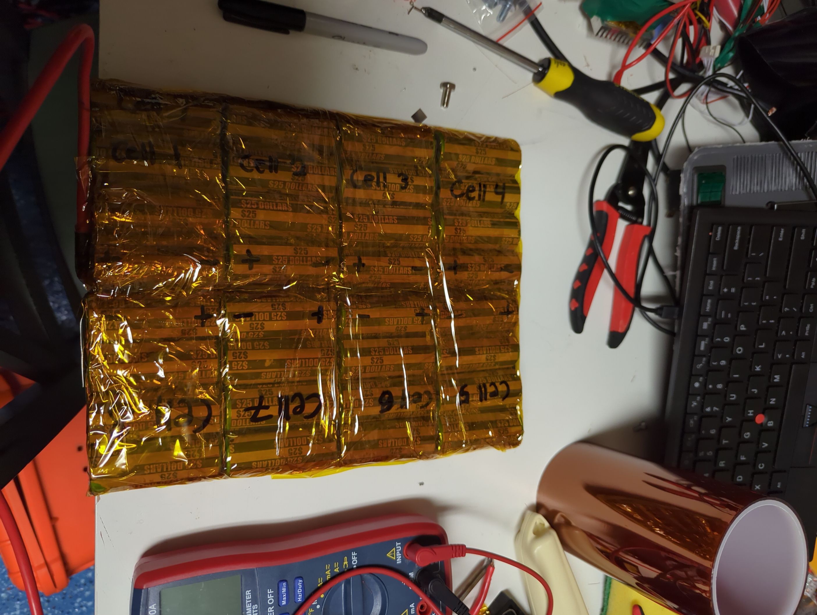
- 8S4P Battery Pack
- Nominal Voltage: 25.6V
- Fully Charged Voltage: 29.20V
- Fully Discharged Voltage: 20.0V
- Max Continuous Discharge: 120A
- Max Continuous Charge: 24A
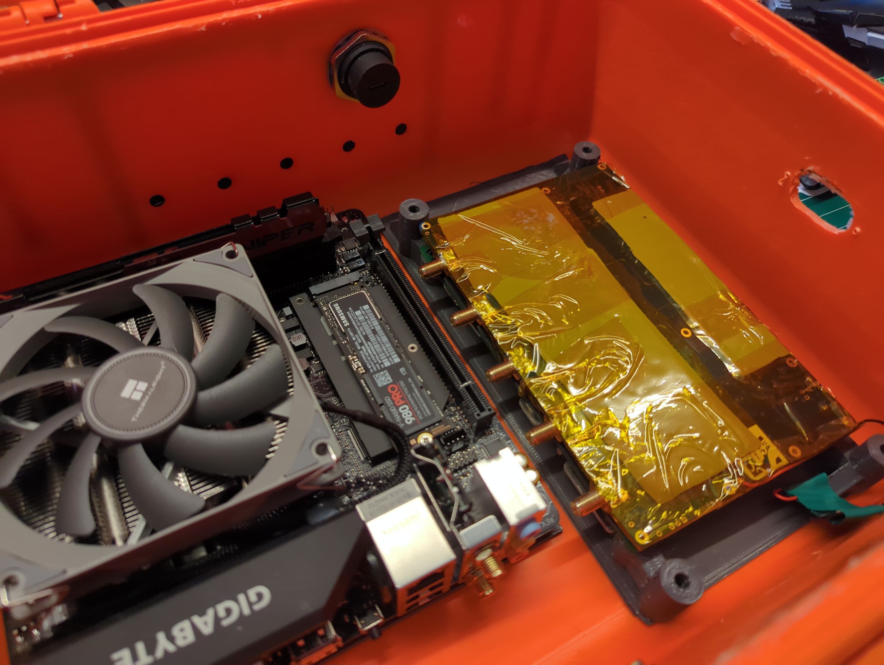
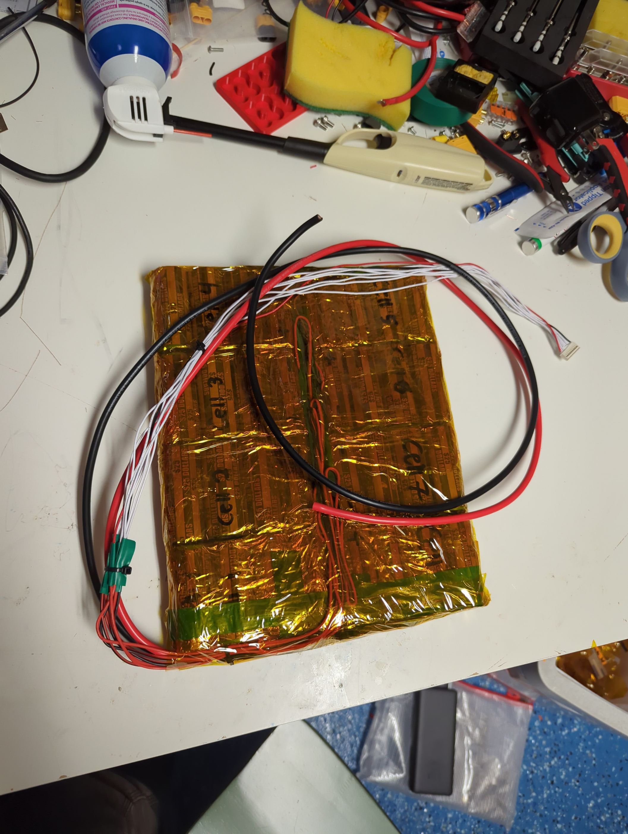
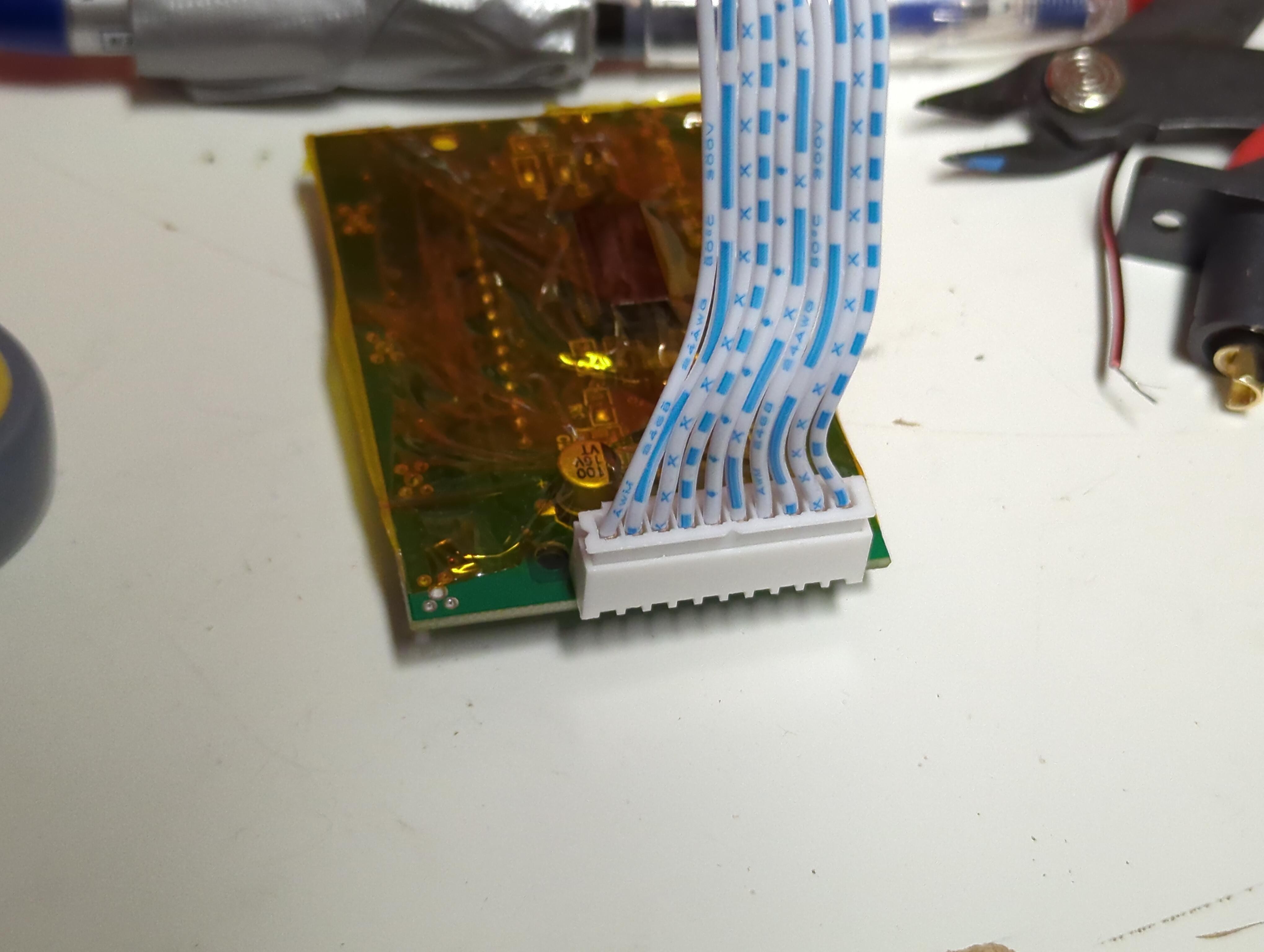
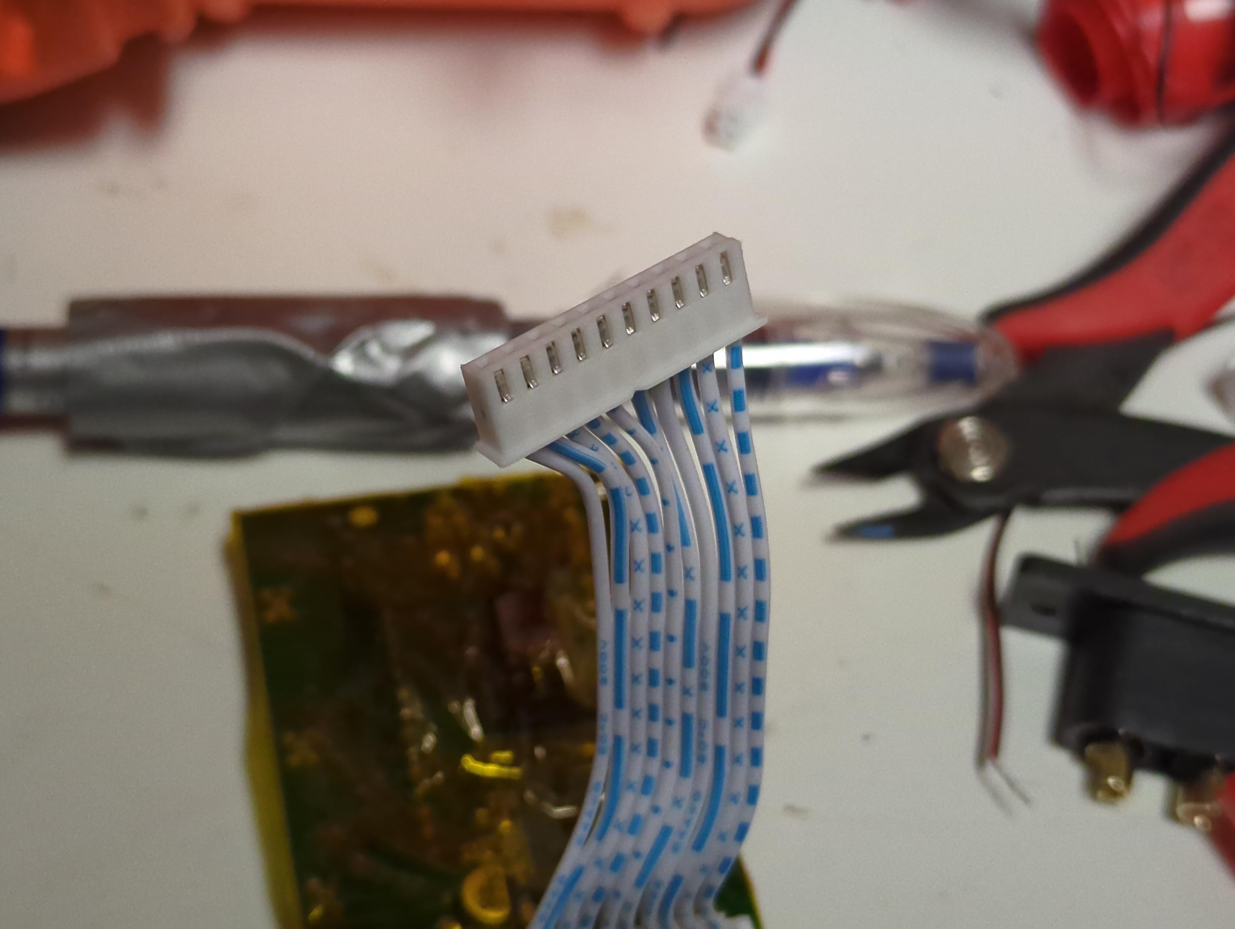
The battery pack is custom made using these used Sony cells and hooked in through a JiaBaiDa (JBD) BMS to protect the finished pack. The resulting pack has a nameplate capacity of about 300Wh, which is likely to last quite a long time doing simple tasks, but a but under an hour when doing something intense like running machine learning locally. The entire pack is wrapped in kapton tape to keep it in a nice solid unit.
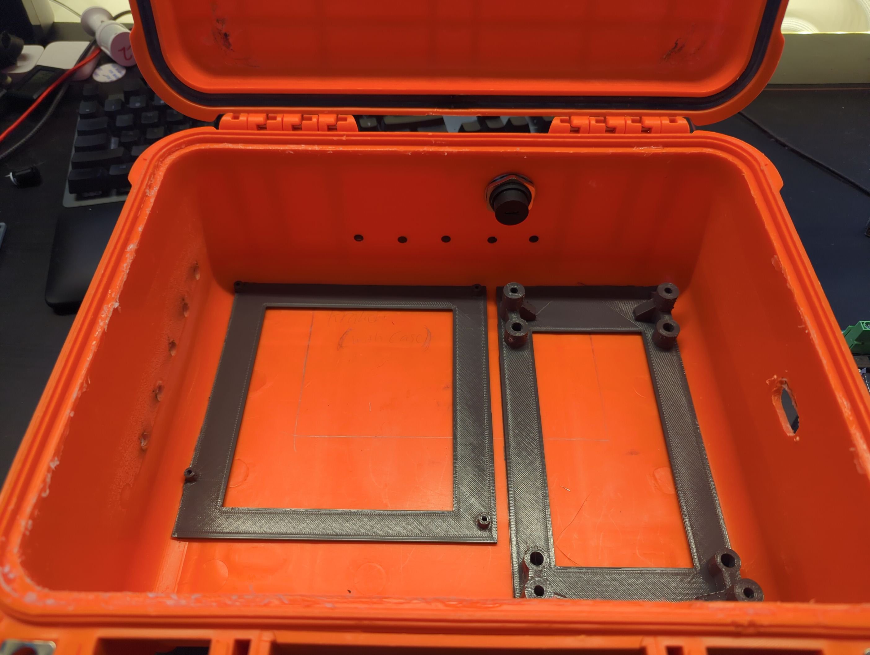
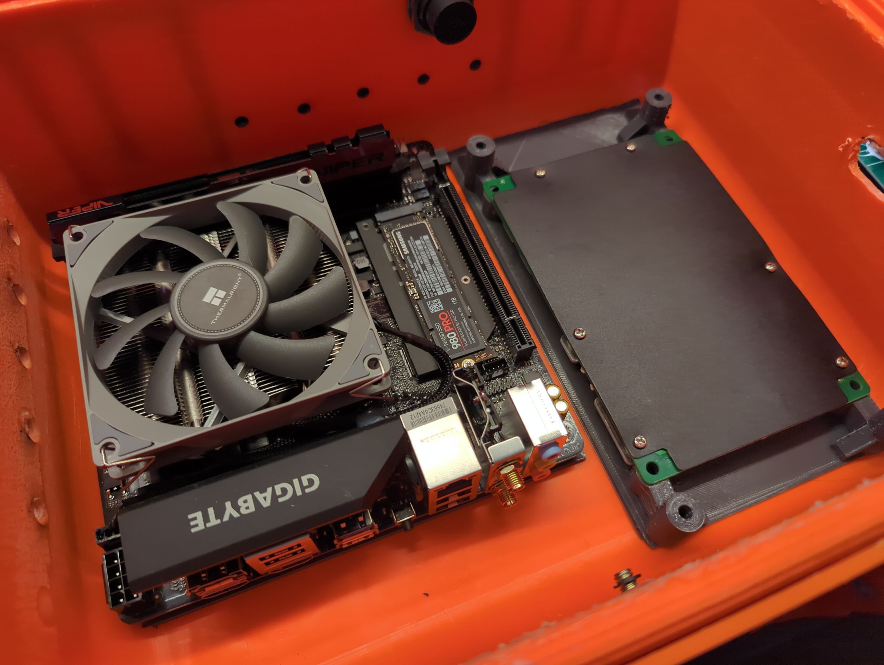
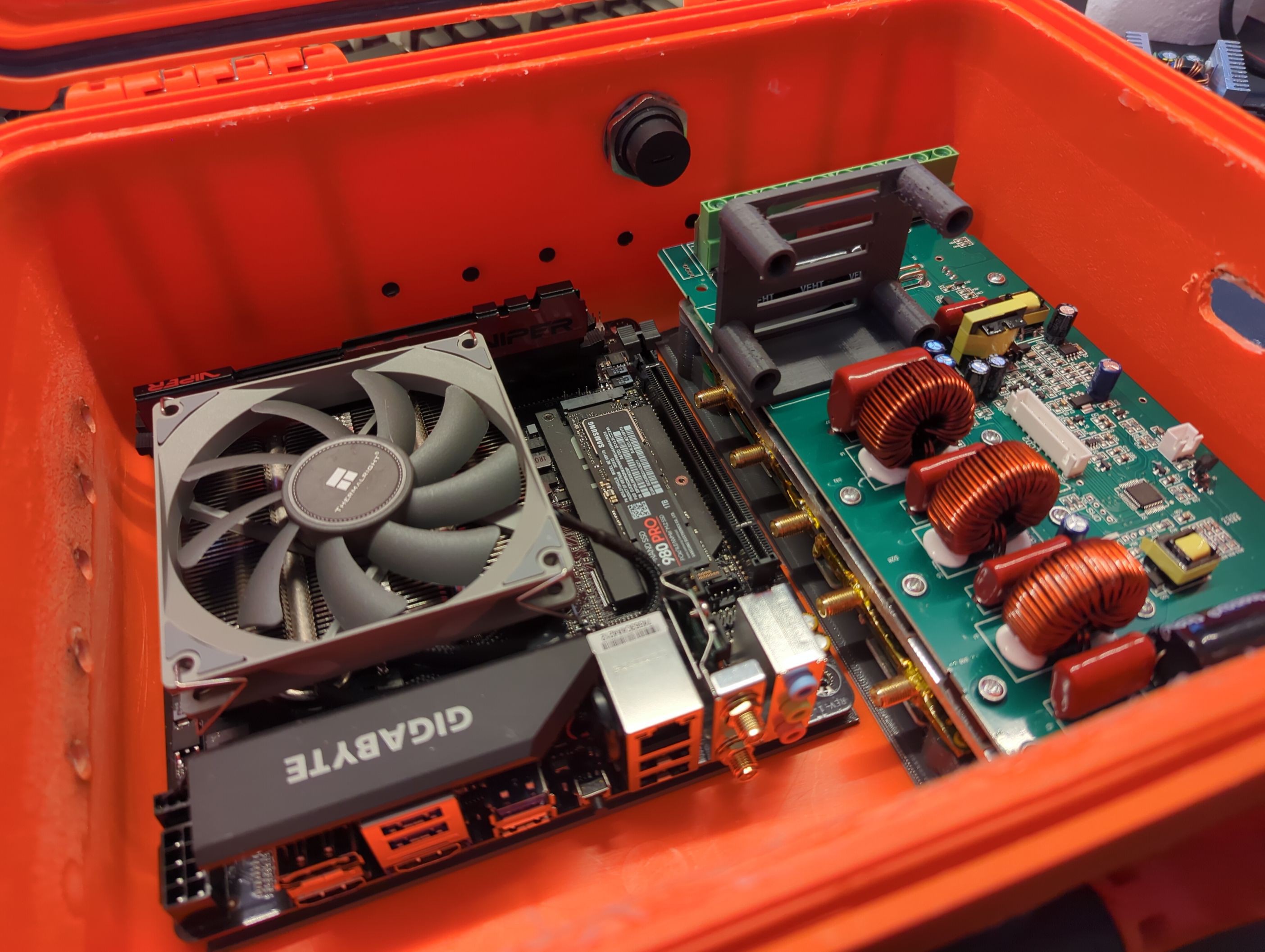
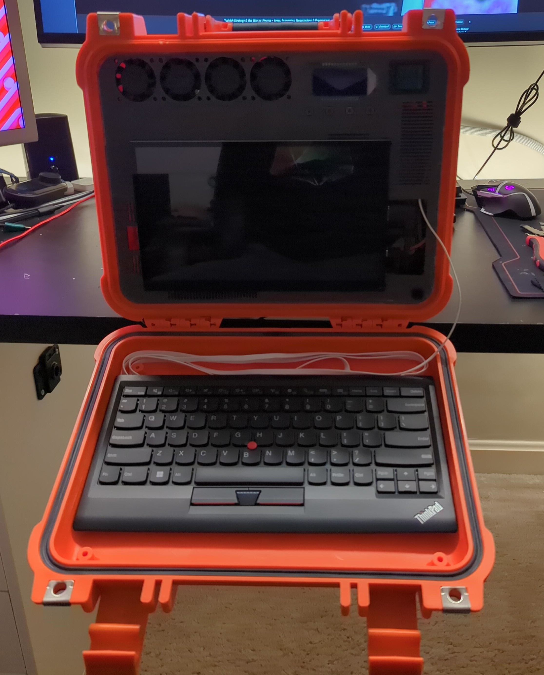
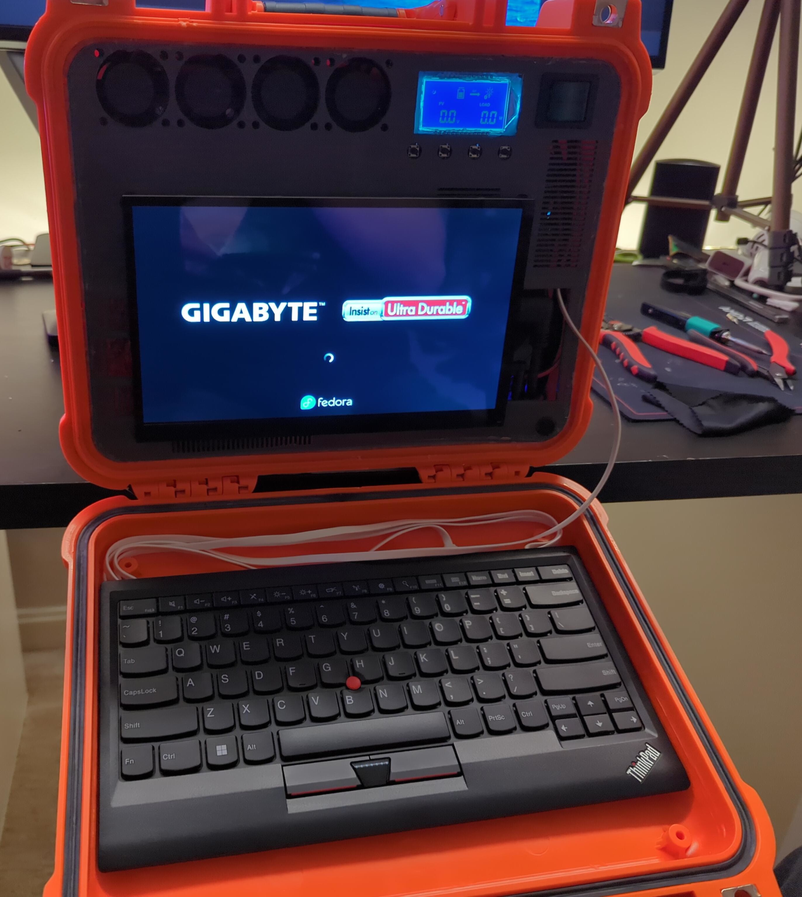
Computer
Most cyberdeck builds are running raspberry pis, or some similar ARM based SBC.
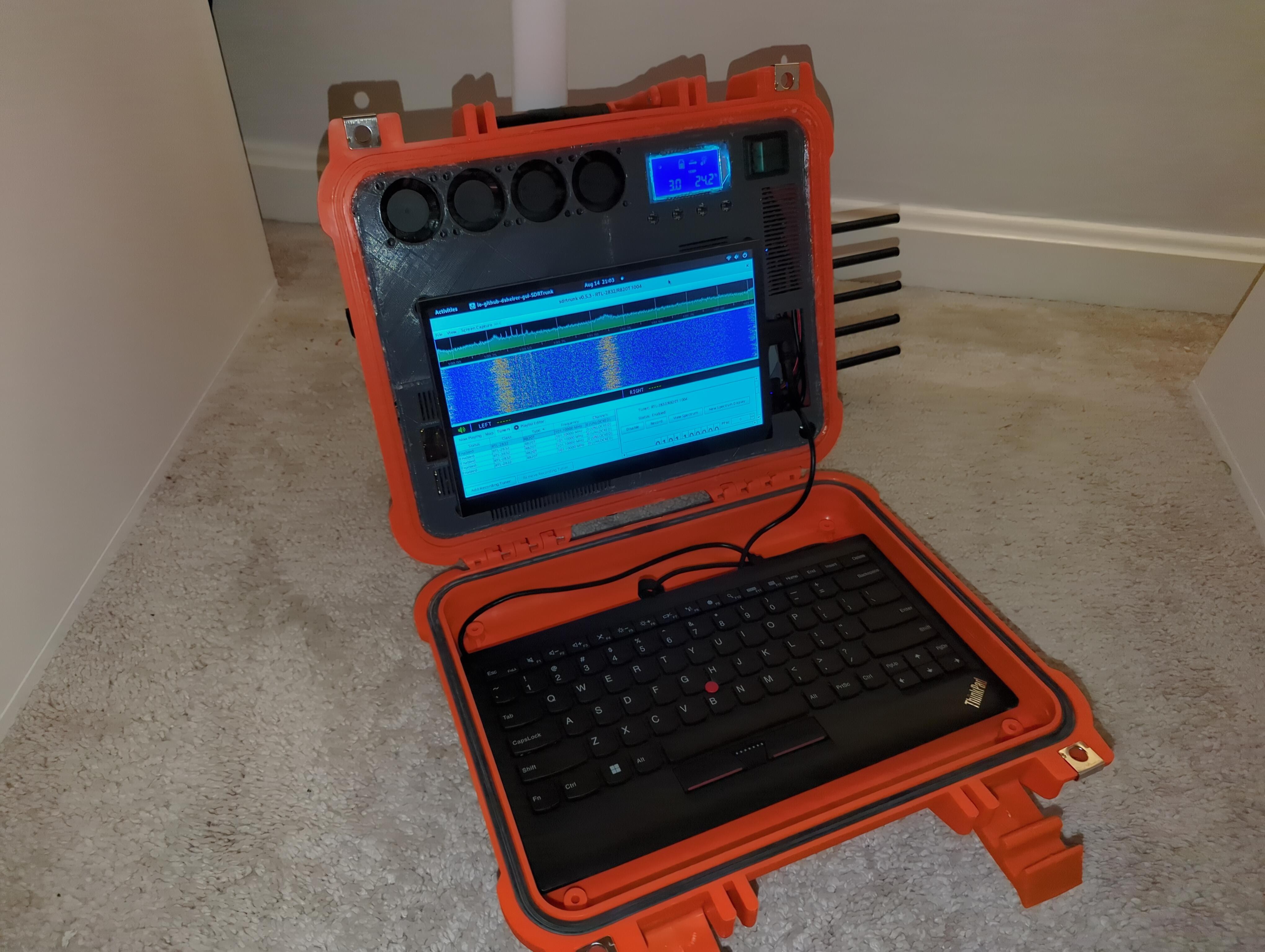
Unfortunately a lot of the software for radio isn't compiled for ARM (which, obviously has a non-hardware solution), but even when it can be made to function, working with software such as RTL-SDR taxes most laptops, let alone SBC's. The solution? Make a maxxed out rig to take out into the field to run all sorts of radio goodies, with power to spare.
Additionally, there is the option to run local machine learning. While it might seem strange to want to do so locally, there are some quite valid reasons:
- Live captions of radio conversations
- Live captions to support a beginner stenographer at live speaker events
- Transcription of recorded radio conversations for analysis and querying
Since radio is used in a lot of places where internet is unavailable, it may not be reasonable to farm out to a GPU cluster.
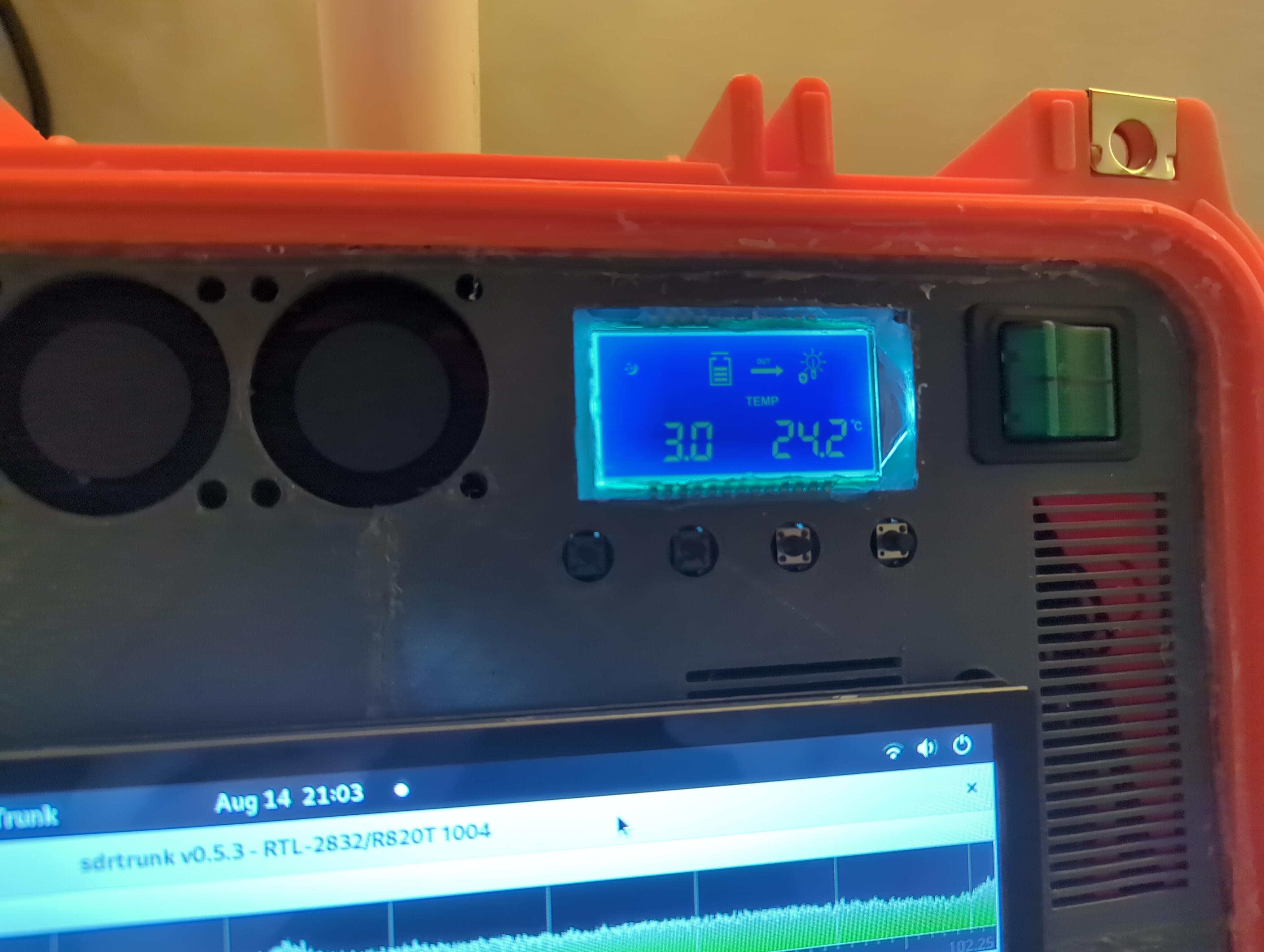
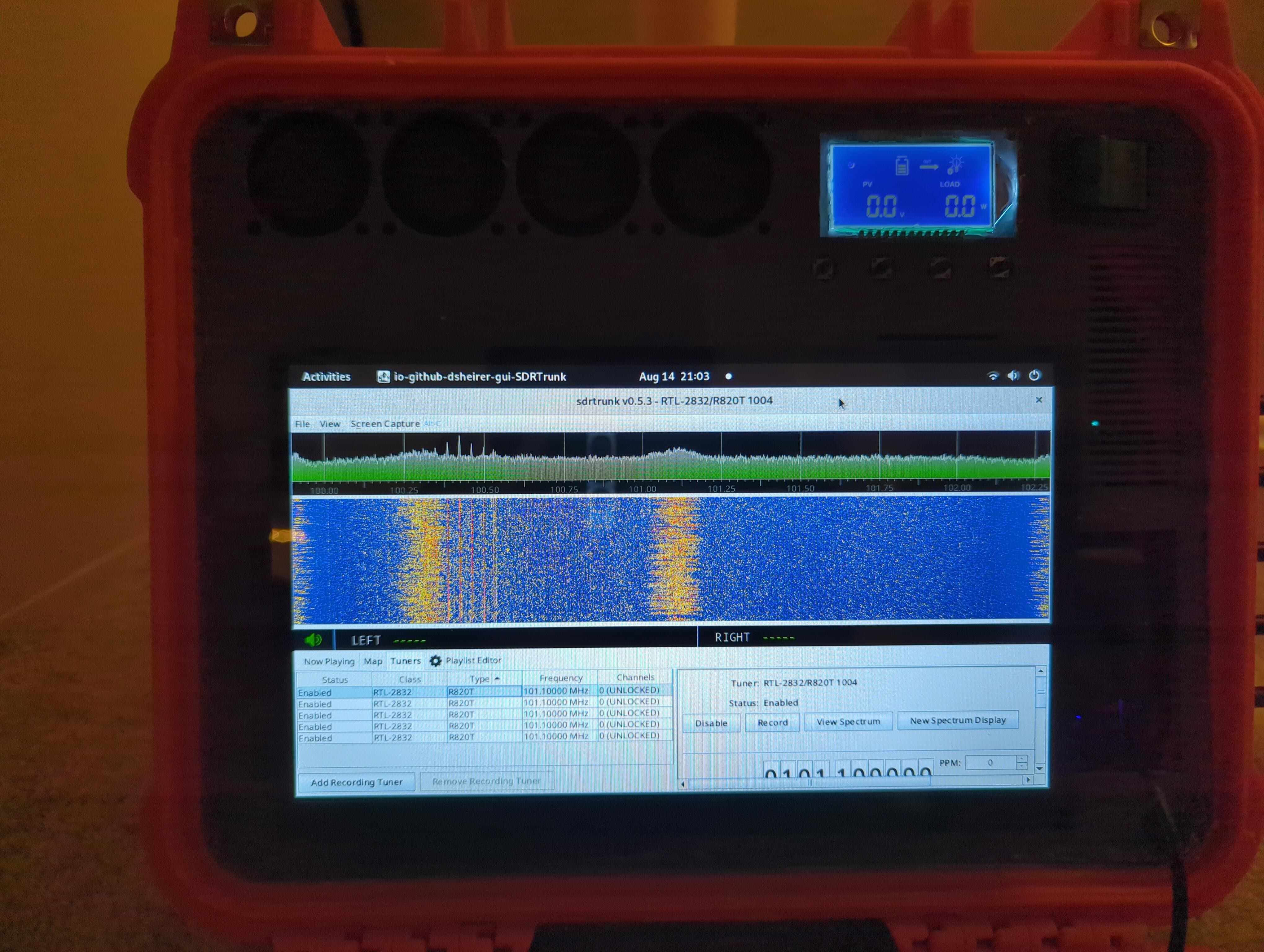
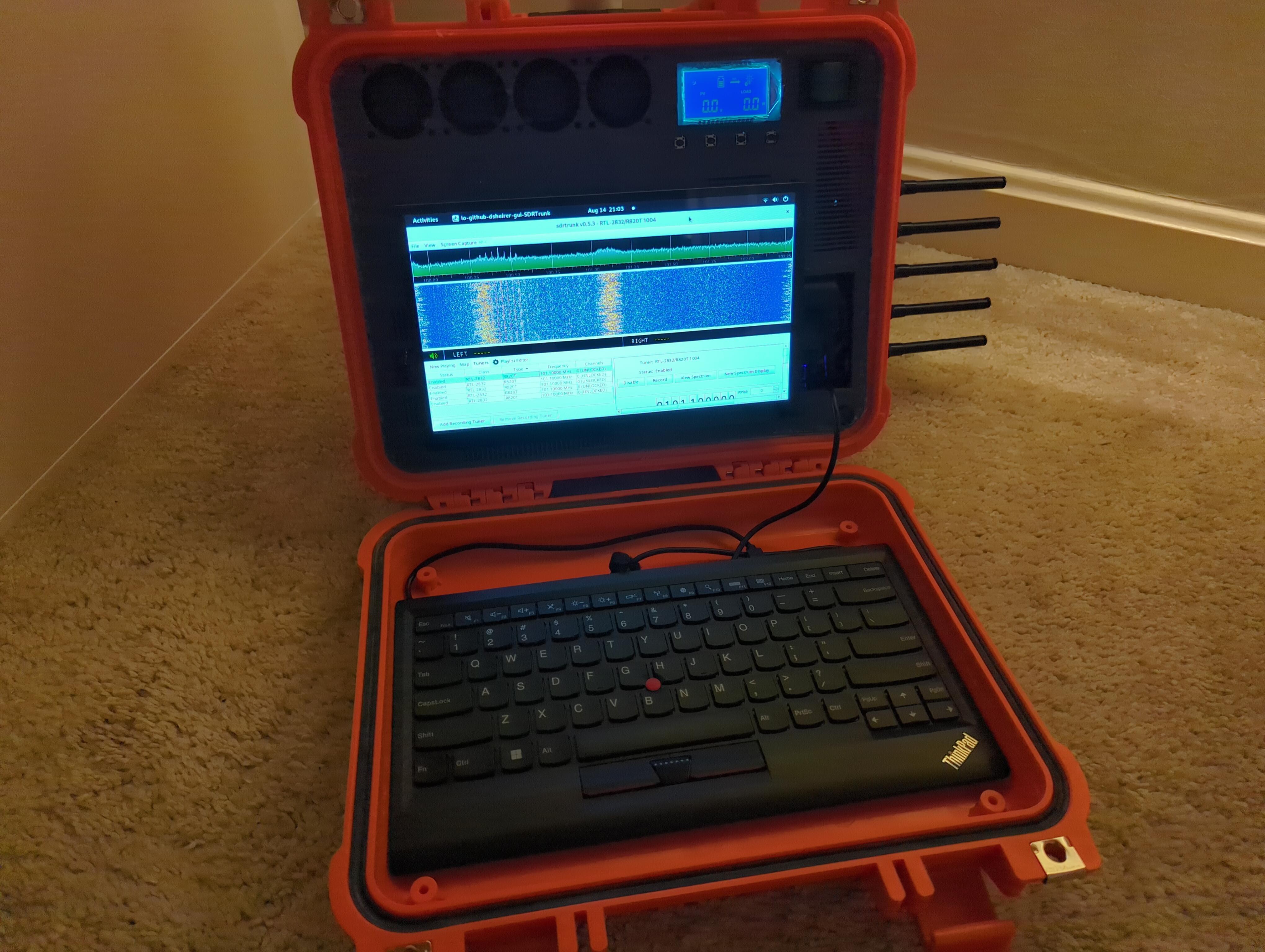
Radio
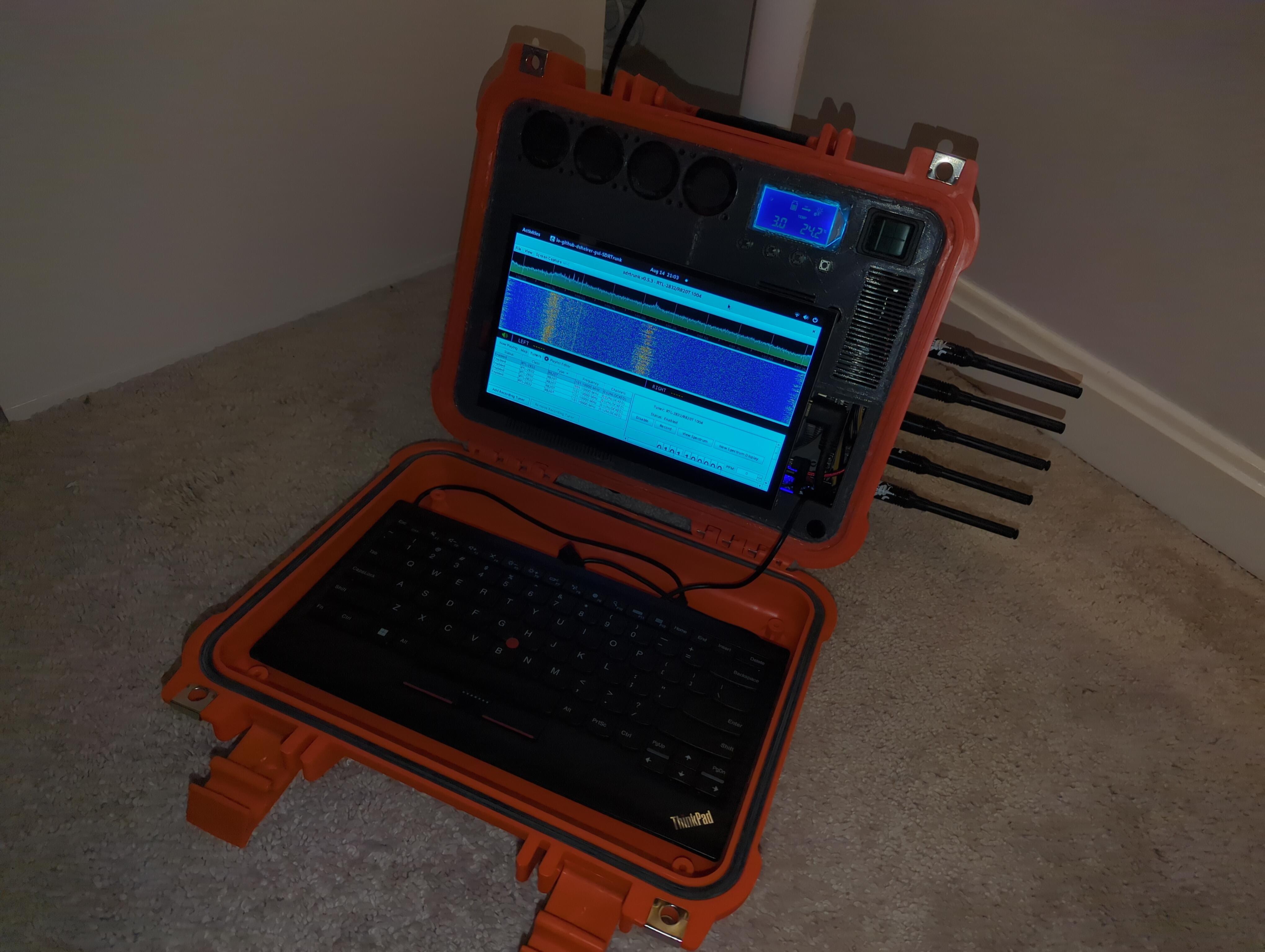
Thankfully Kraken SDR is a ready-made all-in-one board that gives me 5 RTL SDR boards, which is sufficient to listen to 2 or 3 P25 trunked systems at once, It just needs a 1A USB C input which can be provided by the USB power adapter. The data line is a separate USB C output that can be connected directly to the PC.
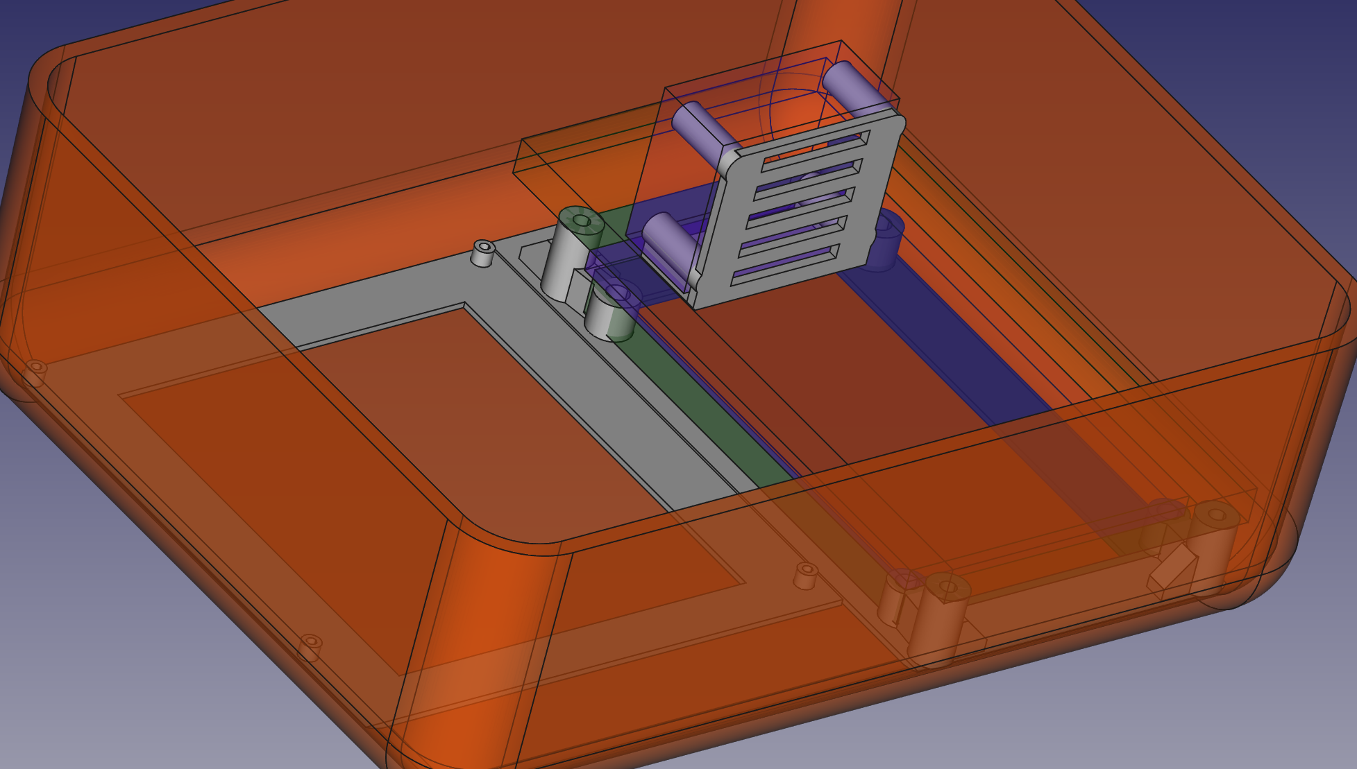
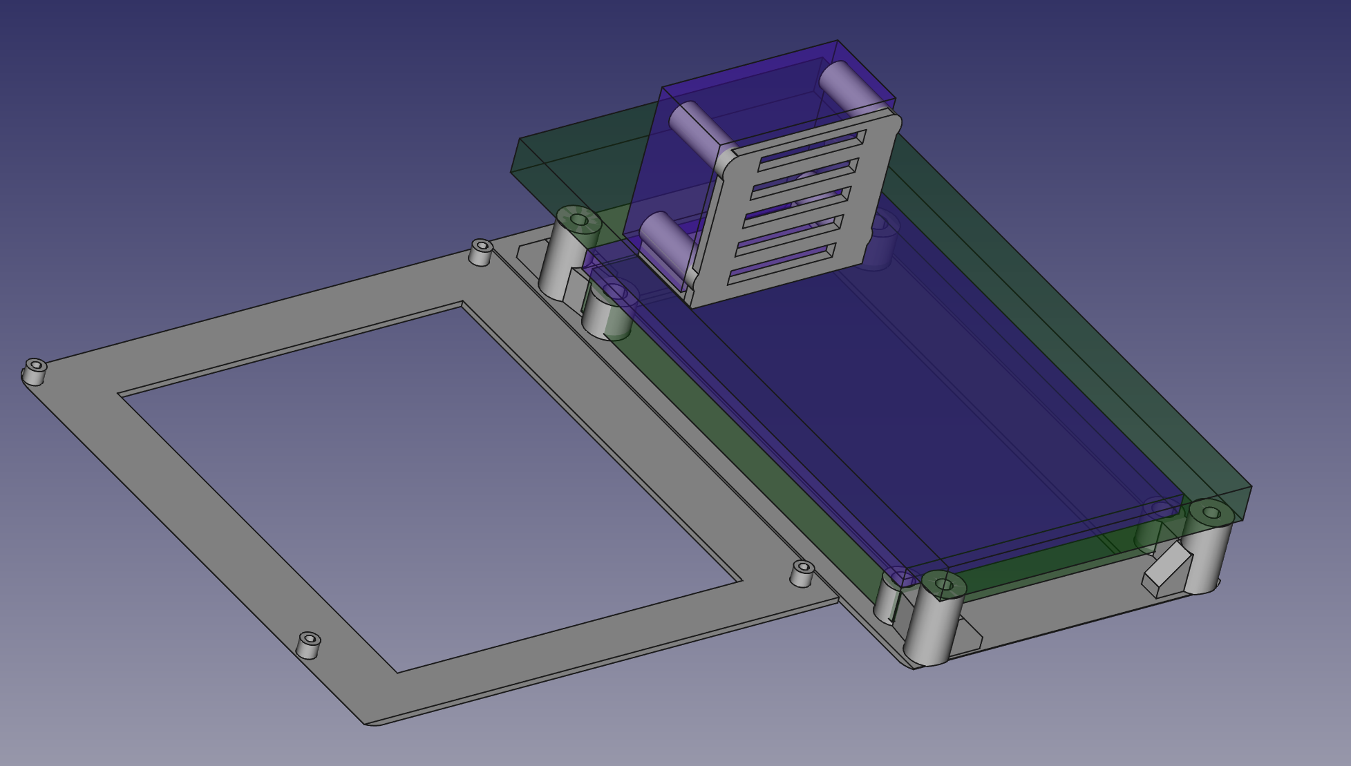
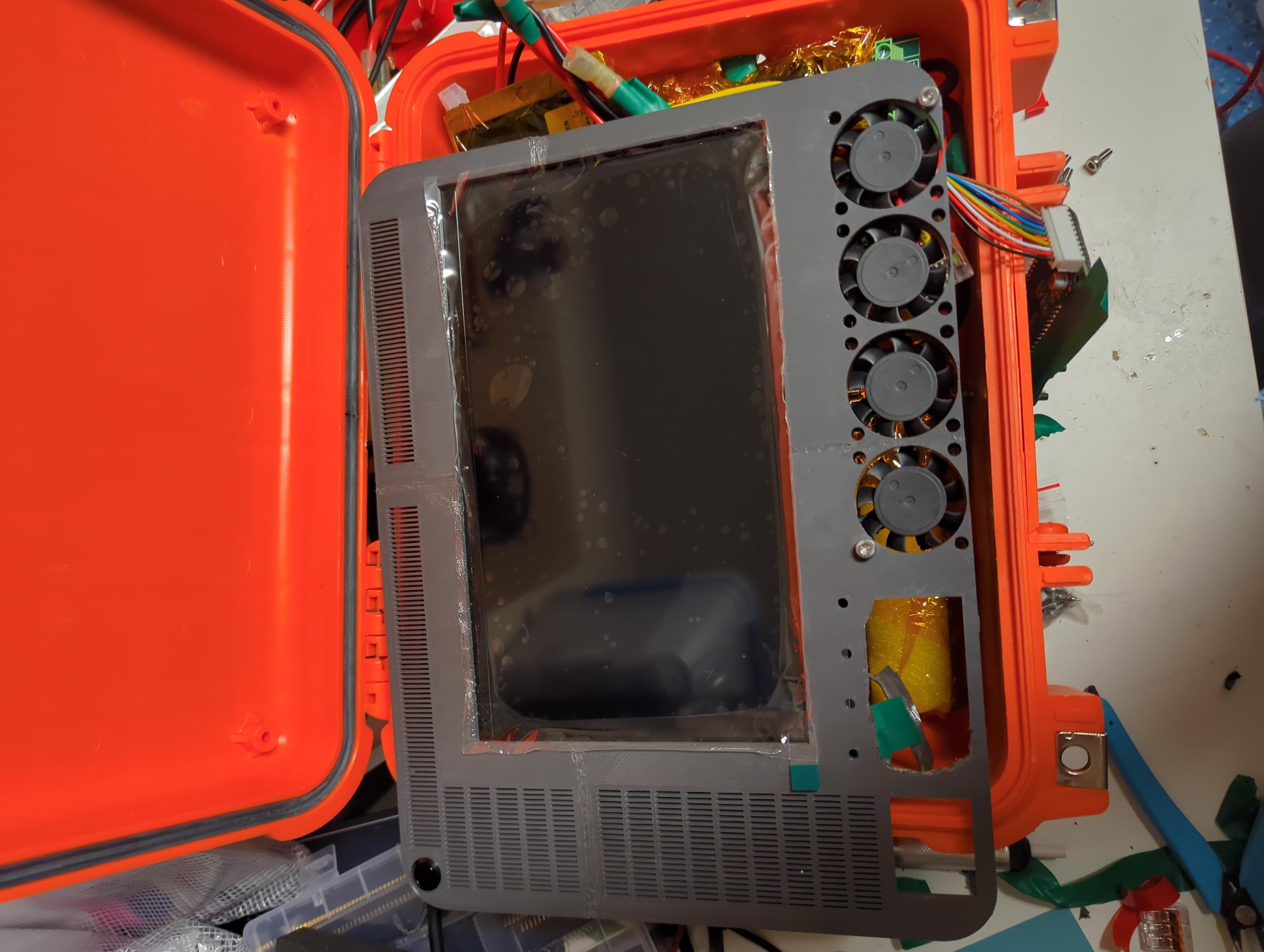
Cooling can be provided by using thermal pads to spread the heat out to nearby components, and allowing the fan airflow to cool the entire system as a whole.

 Drew Pilcher
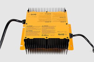
 leadacid44
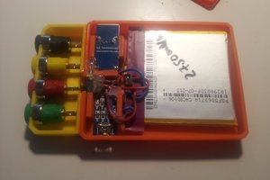
 davedarko
 Tron9000
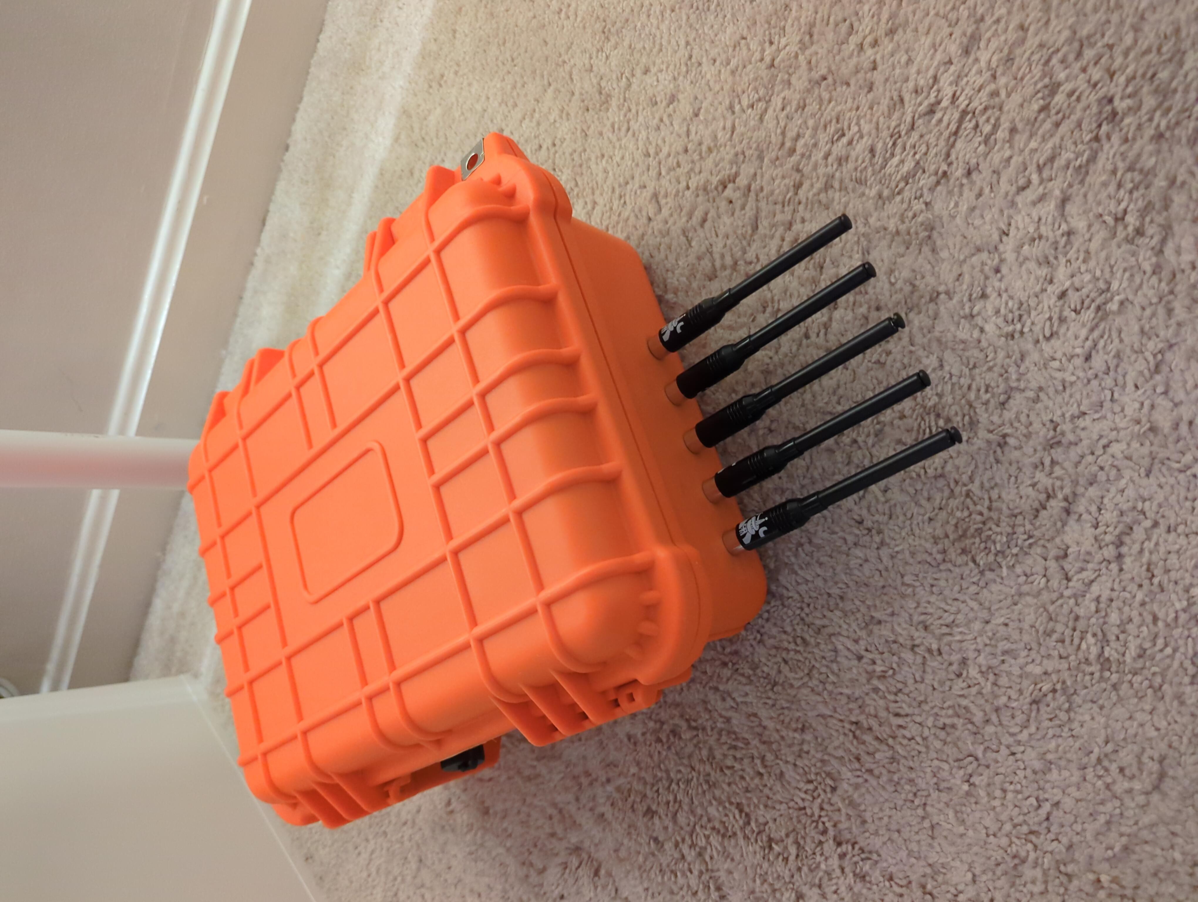
This is a superb project, love the tidy battery work and that for once someone did a cyberdeck without a RPI. Also cute keyboard i didn't know they made these with a pointer :)
Best of luck onwards!