 Abraham Limpo
The project consist of the following parts:
* A hardware enclosure, designed in FreeCAD
* An arduino nano providing a serial to parallel converter service for the HD44780 screen
* A node app that updates the screen with relevant information
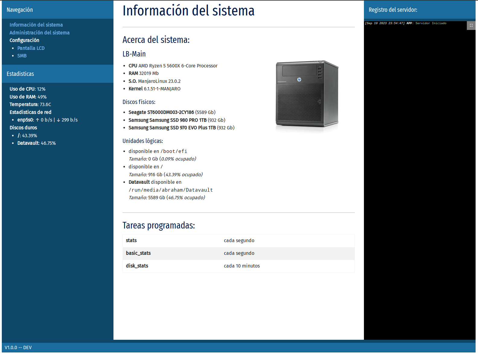
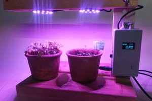
My father has this fileserver that is not connected to a monitor, so I decided to put a small LCD display to display useful info
Already have an account? Log in.
To make the experience fit your profile, pick a username and tell us what interests you.
The project consist of the following parts:
* A hardware enclosure, designed in FreeCAD
* An arduino nano providing a serial to parallel converter service for the HD44780 screen
* A node app that updates the screen with relevant information
For the last post let's put some thigns that may be of interest, but did not fit the previous project logs:
The project took a total of two weeks' evenings -plus at least a full-time weekend- between researching the project, testing, prototyping and assembling. I could probably replicate the project in a couple days now, as the main time eaters where printing the prototypes (the faceplate was only 90 minutes, but the bottom part was 9 hours, and the top about 3), and the trial-error of fitting the components.
I chose the materials because I had them on hand, but replicating it should not be expensive, provided you can find an arduino nano at an acceptable price. The BOM - taking prices form mainly amazon - goes like this:
Assuming you already have the wires, PCB and headers, this project can be done for about 20-40€, depending of where you have to source the materials - buying in bulk is cheaper but what use does have if you really only need one?
As for tools, you will need a soldering station (I actually did all the work with my pocket soldering tool, as wire-wrapping wire really doesn't need much heating), a wire stripper and crimping tool (don't skimp on the money, a good tool will save you time!), wire cutters, and obviously a 3D printer.
While outside of the scope of the project, I integrated the LCD interface in a piece of software I wrote so my father doesn't need to SSH on the computer to shutdown it.
The app offers a system based on extensions that they are mostly independent of each other (I still have to declare dependencies in the root package.json, so I cannot just drag and drop them), coded on a base that offers simple services (serve menus, fetch info, schedule tasks, etc). This is what runs the periodic backup on the server, and now it also runs the screen.
As I mentioned, I got...
Read more »While I don't have photos of all these fixes, because I was rushing to get them "shipped" before delivering the PC back to my father, here's a list of things I fixed:
With this, the project was finally ready for delivery.
As I mentioned a couple posts ago, my original plan was to use LCDproc, an old but still available linux app that communicates with a plethora of LCD models, including a free atmel based implementation (the "serializer"), which later was adapted to arduino.
Unfortunately, LCDproc is meant to be used in 20x4 LCD screens, which are much nicer, but also too big to fit inside a single 5 1/4 inch bay, unless you implement a bespoke PCB like what matrix orbital does (and even then mount the 20x4 in a double bay, though they have a very nice graphical LCD which, if I lived in US, i'd probably would have bought).
Fortunately, what LCDproc does is simply sending HD44780 commands through the serial port, which the arduino then "parallelizes" - in our case, "nibbleizes" as we are using 4 bit mode - for the screen to consume, so it should be trivial to write an application with your favourite language to talk to the screen. And because I had like 3 days left, I chose Javascript.
Node.js does not possess in-built serial port libraries, but there's a fairly light and decent one called serialport. Initial tests seemed promising, but I encountered a weird issue while testing in manjaro: It seems that the OS is creating the ttyUSB0 ports as read-only, even for the group (only the user, root, has write access). I had to modify the /udev/ to change the mode to "group RW" in order to run the app as user.
While I could procure much of the hardware info using the node libraries, systeminformation enormously simplifies the process of collecting the info, and thus the second part of the puzzle -how to get the info- was solved.
The app itself is a simple afair. Each "screen" is a self-contained function that fetches the info and sends the necessary commnands. The push of one of the two buttons increments or decrements the "active screen" counter, changing which screen is going to be displayed next.
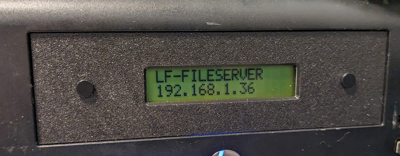
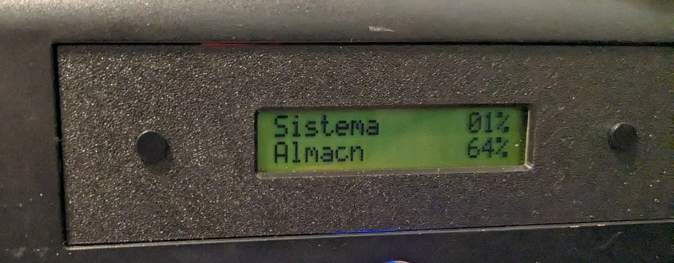
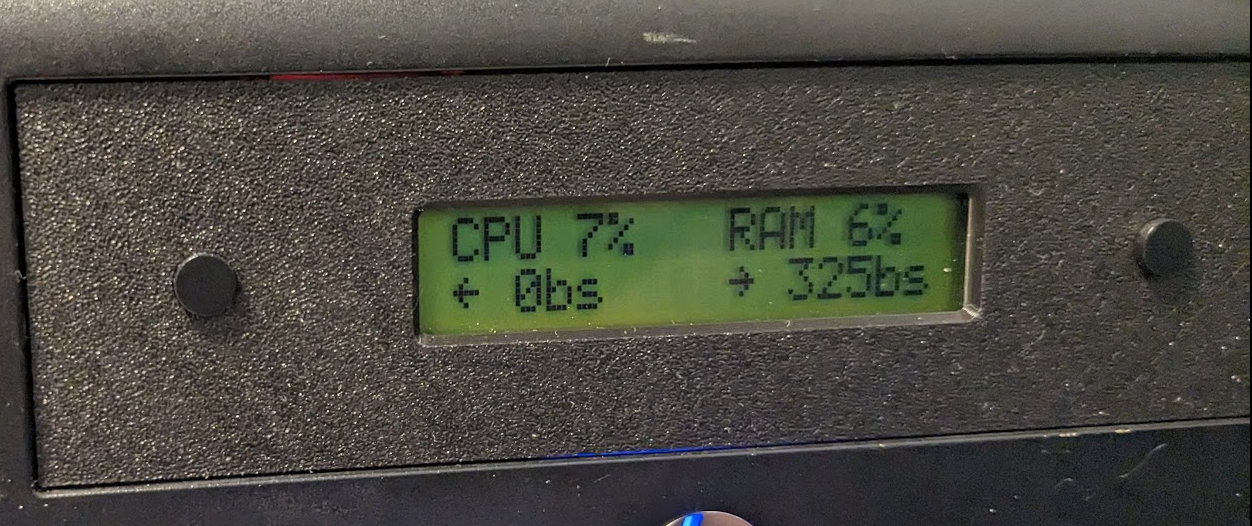
The four screens I designed for the system:
Screen 1: Hostname and current local IP
Screen 2: System and Storage Hard drive usage
Screen 3: CPU and RAM usage, and upload and download speeds
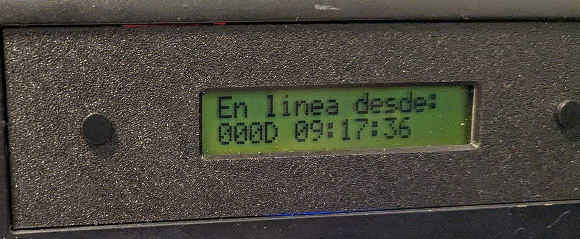
Screen 4: System Uptime
After setting up the app as a service (which also made redundant my udev fix, as the service ran as admin), the project was ready to be delivered, and with a day to spare!
My original plan was to use LCDPROC, and being an old library, there was a high chance someone already did the work for me. And lo and behold, there was! In this particular case some chap from turkey already implemented something similar back in 2011, and in his Github Repo it had a sample INO project i could fork.
His project is essentially an expansion of SerialDisplay example for the LiquidCrystal arduino library, but adding some niceties like the ability to send commands, and a nice "disconnected for x time" counter.*
The only thing it lacked was some way to read the buttons and communicate them to the user. I opted for sending A and B in response for button presses. The system does not support keyup or keydown, only keypress, but could be easily modified to do that if needed. It also lacks any kind of real debouncing.
Also, the disconnection counter has an amusing bug that I did not bother to fix. As it uses an int to get the seconds, is way too easy to overflow if you leave the LCD plugged in without the software for too long. I'm guessing I could change them to uint32_t as the timeoutCounter and lastTimeReception variables and that would fix the bug.
In any case, for the purposes of what I needed this was enough, and I can always go back and improve it.
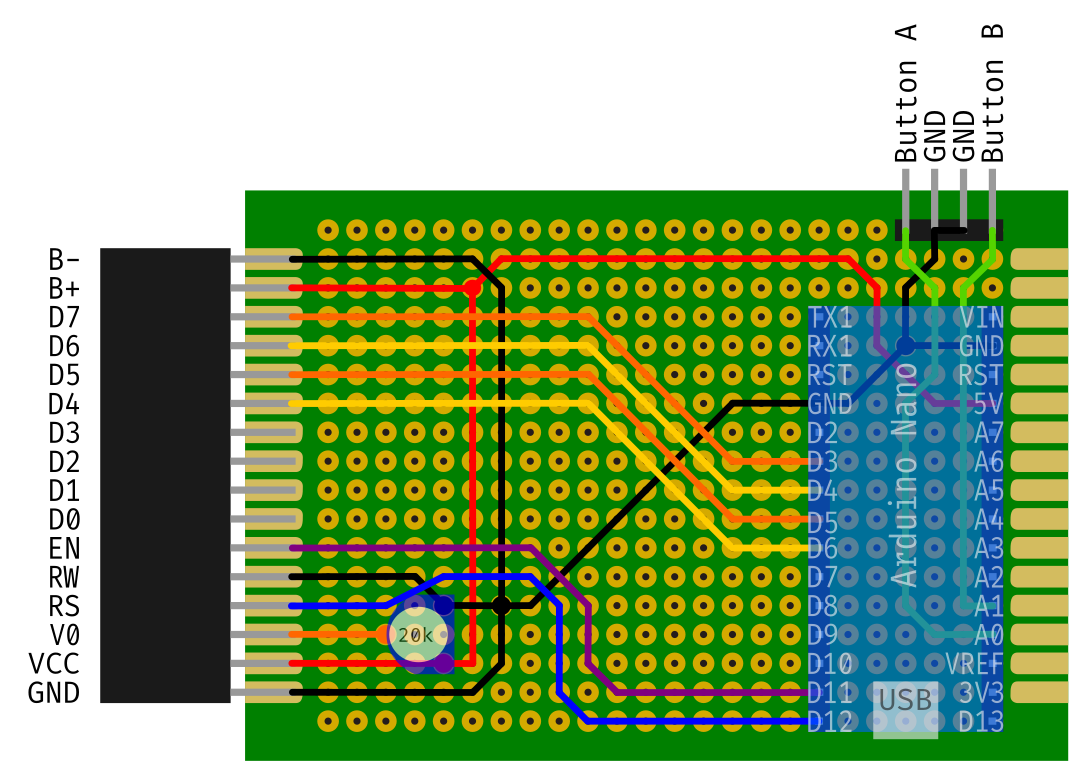
In the end I decided to go for the "mess of wires". The good thing about this approach is that the board is extremely simplified, as you can reroute the wires as you want on the connectors. Here's the diagram:
There are two JST 5 connectors on one side, one for data and one for power, plus other two JST connectors for the buttons on the other side. I also noticed that at some point the reset button started to fail (these cheap clones...) so I removed it and put a nice button on the extra space of the board.
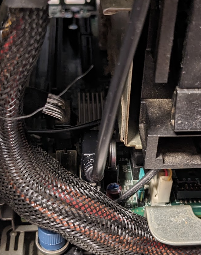
And here is how it looks in the end:
Yeah, so much for cleanliness. The board is mounted with double tape adhesive above the SSD hard drive. The USB cable is routed below the printed box through a hole in the case where the HDD power cables are stored. From there it goes to an internal USB connector (that originally was meant to put a USB boot stick for simple OS's). As I mentioned in the previous post, the 20cm cable is WAY too short. If someone follows these instructions I would say to use a normal cable and route it through the back. It will also make assembly and disassembly much easier.
To complete the assembly, we screw the top part to the faceplate and secure it to the bottom, and we can close the computer.
So now we only need to know how to make them talk to each other.
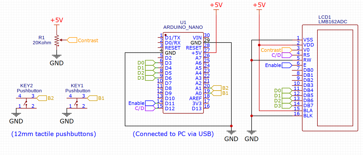
The PCB is fairly simple, here are the schematics:
My first idea was to directly mount the PCB into the screen. That would make the interior less messy. This is the circuit diagram:
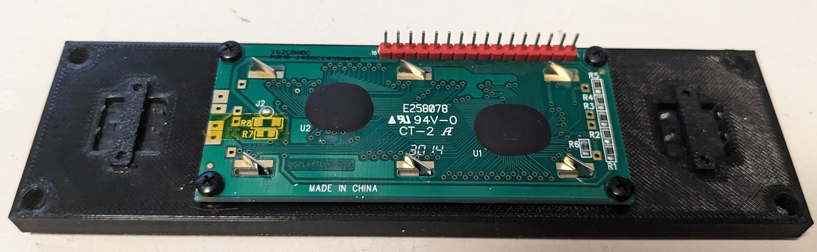
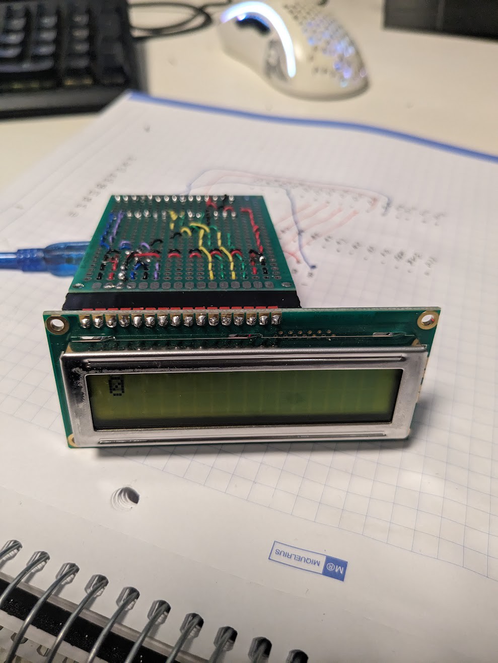
You will notice that the screen data lines are reversed respect to the schematic. This was for convenience sake, as the LiquidCrystal library allows you to arbitrarily assign the data pins, and that way the wiring was easier. Here's how it looked once assembled (but before I soldered the button header).
(and yes, the paper below the circuit is the original diagram. I just cleaned it up for you guys :)
You will notice that the USB cable sticks quite a lot from the side of the LCD. This proved to be a fatal error and when I tried to plug the cable it would simply not fit inside. I bought a 90º cable but even with that it was too big. I would have to redesign the circuit board with the arduino flipped, but also the cable I bought was a bit too short, so i had to choose: buy another cable, and redesign the circuit board the same way -plus risking it would not fit anyway- or go the "mess of cables" way. This project had a tight deadline (I could not leave my parents without the fileserver for more than two weeks, as it contains my fathers photografy work, plus the cloud backup is synced from here).
At least I could use the board to start developing the software:
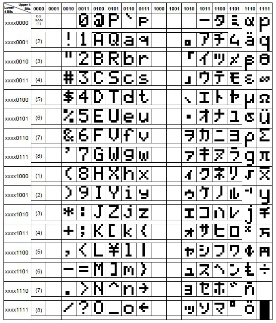
The node app ran all LCD commands except the "custom character" one. I can trigger the display to show characters 1 to 8, but it ignores the command to write a new one. It would be not a big thing. but this LCD uses CHARSET 1 of the two availables:
And that means no spanish accents (except, curiously, the ñ) and no up or down arrow. Also for some reason, trying to write characters from the second half (0b1000xxxx) always resulted in some manner of corruption, so really I'm limited to the 96 characters of the first half.
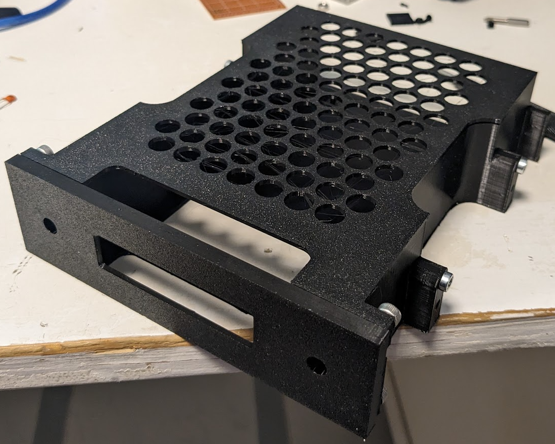
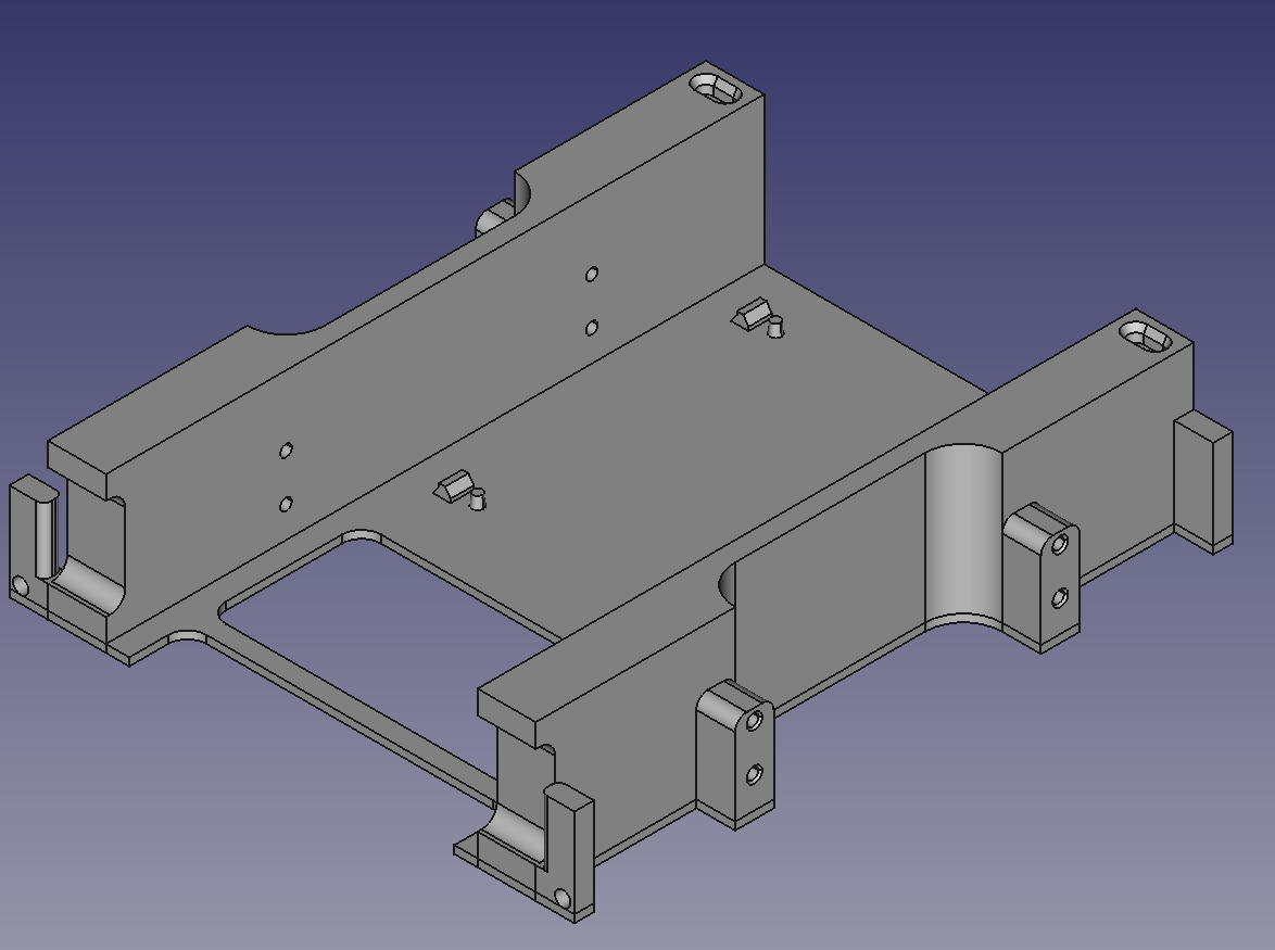
The top plate has a pin that keeps it aligned with the bottom part nicely, and also latches onto the faceplate with screws. The hole design was a nightmare to do in FreeCAD, as hexagonal arrays are not a thing you can do.
If I had to redesign this, instead of securing it to the faceplate I would have made the bottom plate the sole responsable of holding the faceplate, and add a way to attach this with screws instead of friction. It worked, but could have been better. Unfortunately redesigning this would have meant also reprinting the bottom plate, and I was not keen of doing 10 more hours of that.
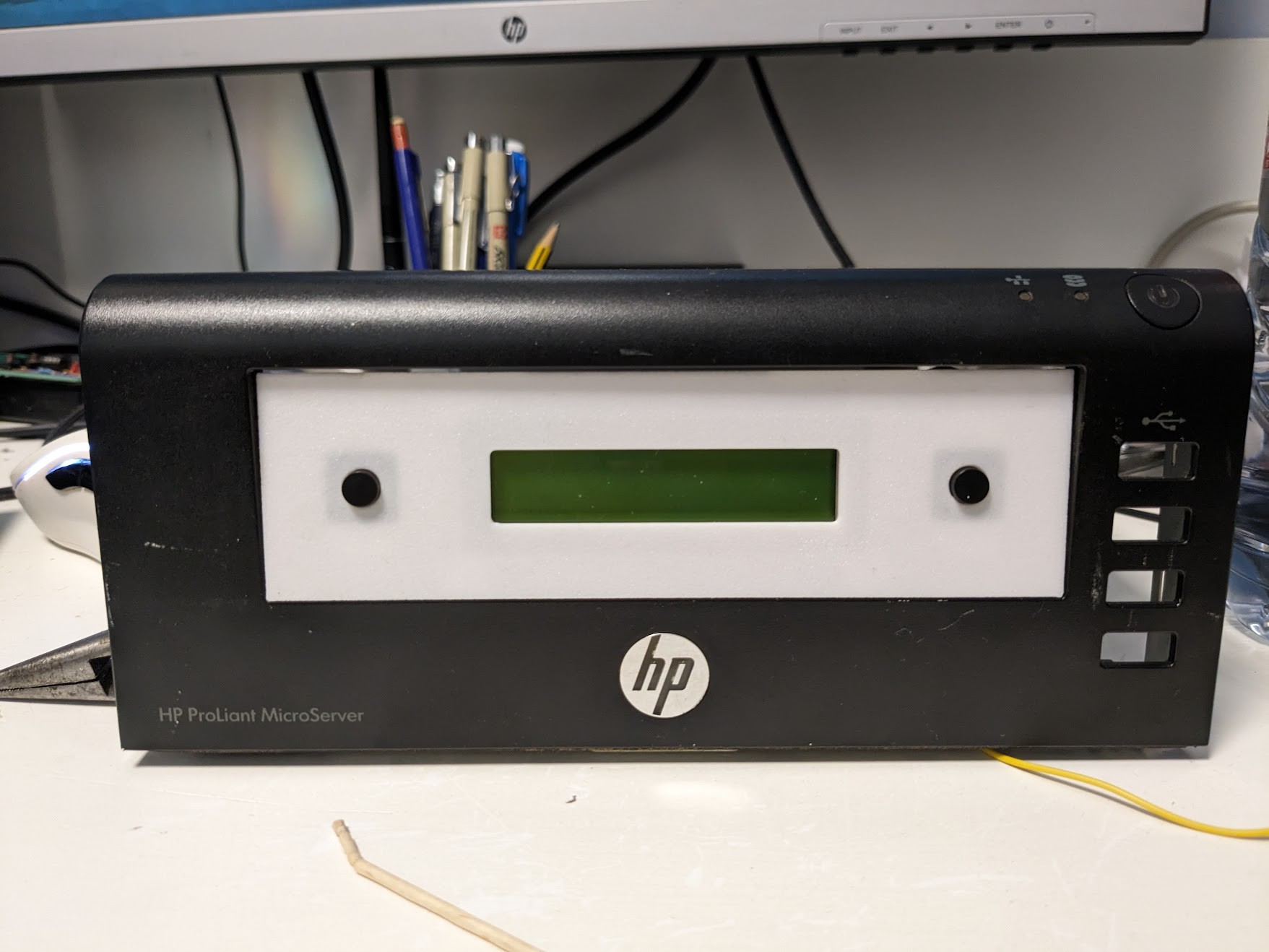
All in all, the model looks nice (ignore the stringing, I could have heatgunned it but nobody but me is going to see it nromally. The top plate does not flex much (The bottom plate does flex a little because of the big holes, but seems this arrangement is much more stiff), and from afar it looks even something you could buy off the shelves.
On this photo is also the reprinted faceplate. The original one had a noticeable texture due to the Monotonic layering (it basically covers everything with a 45º slanted deposition, then it rotates the thing 90º and goes again for the next layer). I switched it to hilbert curve layering which worked much better. The only texture it shows now is the one from my printer surface, but it looks good on this model.
With the front plate designed I had more or less clear what the bottom plate should do:
* It needed to hold the front plate securely. I don't plan to remove the thing often but if I need to do maintenance I don't want the thing falling apart inmediately.
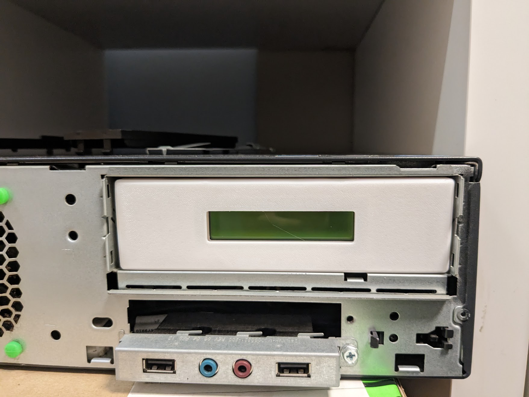
* It needed to be compliant with the CD-ROM specifications, regarding measurements. The microserver uses a non-standard rail system so I could not just drop something with the same size. The screwholes in particular should be within the specs regarding position.
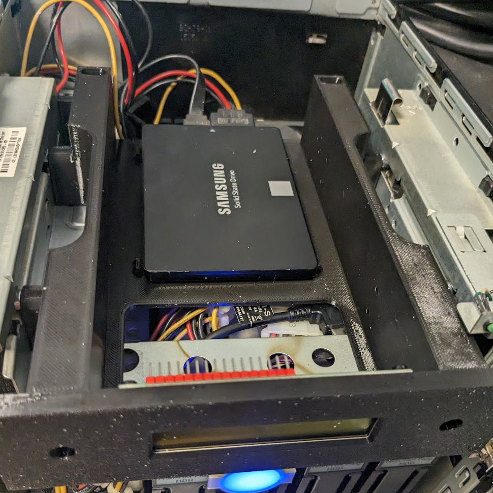
* The CD bay contained a 2.5 inch SSD. The bottom plate needed to keed the drive secure inside
This is what I got
After an excruciatingly slow 10 hours of printing i got this:
The base slid in and out nicely, and the hole allowed the USB cable to pass through nicely.
In a future design I would make the drive guides a bit taller, and also add a back limit so the drive is easy to align with the pins that keep it in place.
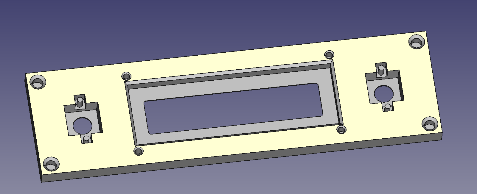
I started by doing a quick front plate prototype
While the screen fitted fine, this one was not satisfactory for two reasons:
* It was to narrow: I followed the inner specs of the CD-ROM implementation and not the bezel specs. I though 2 mm would not matter that much
* It lacked personality: The LCD screen looked way too small in all that plastic bezel. it needed something.
(it also was way too thick, as the specs called for 8mm screen depth, and it was clearly not that.
I decided to add some 12mm buttons to fill the space. They could be used to switch between different screens or call for actions on the server if needed.
This revision was much better, though it still had too much depth for the screen. As I did not want to make the front plate thinner (the specs call for a 5mm bezel) I just made the inner pocket less deep and put a chamfer on the screen edges so it would not be that noticeable.
Dry-fitting the components, everything seemed to work fine, at least until I tried to insert brass screw-holders, and they filled with melted PLA. Fortunately seems that the screws hold everything fine enough without the brass inserts, though I don't think it would last several uses.
Before starting with the project I wanted to make sure I could work it properly. So I made this horrible, horrible prototyping board. The video shows the screen running the autoscroll demo from the arduino library.
After that I did a relatively compact board to test the content.
At this point I was not still considering adding buttons to the system.


 RossGK Tangibles
 Maciej Witkowiak
 Kert
Kert
 Matias N.