Close
0%
0%

Low-Cost Touchscreen Anywhere

An acoustic 'touchscreen' interface that can be easily attached to a variety of surfaces.

Similar projects worth following
The device uses an array of piezoelectric vibration sensors and an ARM microcontroller (LPC1114) to determine the origin of a vibration on a table or wall. The location of the vibration could be used as a mouse input for a computer, a location-dependent button, or any number of other things. The final version may have a USB HID interface to connect to a computer as a mouse.

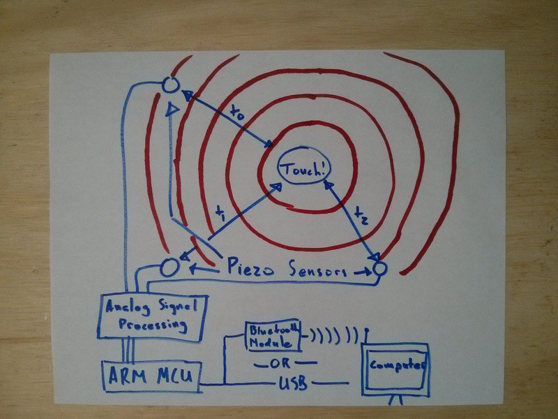
My device consists of three main parts: the piezoelectric vibrations sensors, some analog signal conditioning circuitry, and the microcontroller. The microcontroller detects vibrations from the signal it receives from the analog portion of the circuit, records the times those vibrations arrive, and sends them to a computer for processing. The processing is done on the computer because while the math involved can be solved very quickly on a personal computer, it would bog down the microcontroller too much to be latency-free.

Here's the system diagram:

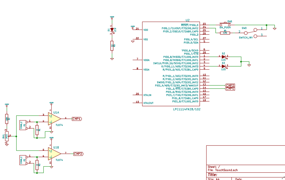
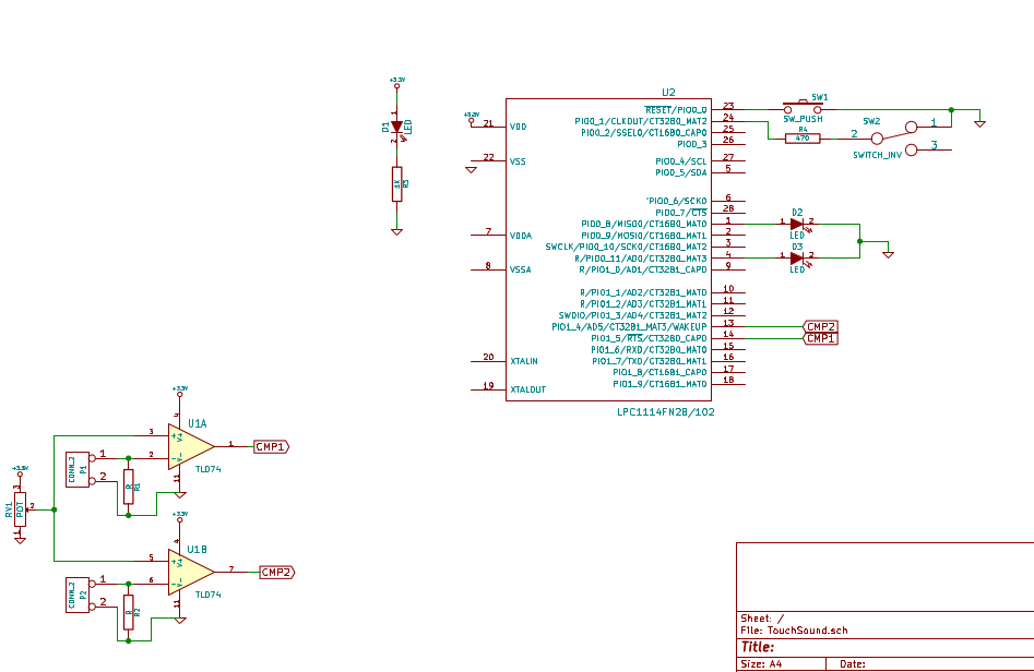
And here's the schematic as of 20 August, 2014:

And finally... the YouTube Entry Video!

  • 1 × LPC1114FN28 Microprocessors, Microcontrollers, DSPs / ARM, RISC-Based Microcontrollers
  • 3 × LEDs Electronic Components / Misc. Electronic Components
  • 3 × Flat circular piezo elements I used ones about an inch in diameter
  • 3 × 1M ohm resistors
  • 1 × 1K ohm resistor

View all 10 components

  • Real Results on One Axis!

    Thatcher Chamberlin08/13/2014 at 21:44 0 comments

    Here's some big news - I've verified that my concept will work! As I've written before, I'm initially testing my touchscreen device in one dimension (along a line), not two (across a surface). This is because the initial circuit I built on a ProtoShield did not give me space to add a third sensor. It's just as well, though, because testing the device in one dimension takes some sources of error out of the equation. In this log I'll show you how I tested the device, what the results were, and where I'll go from here.

    This is the spread sheet in which I gathered data and made a chart.

    Read more »

  • A Detour Into Watchdog Timers

    Thatcher Chamberlin08/10/2014 at 03:18 0 comments

    I'm working on polishing up the code that runs on my board before attempting a full-on test of the system. Remember, you can check out the most recent version of the code here or in the links section of the project page. However, there's been a problem that I haven't been able to get around: the chip just freezes up sometimes. It usually stops in the middle of a printf() call, and since I don't have a fancy debugger, I can't actually see what's going on inside the chip's memory at that exact moment. I suspect the problem is caused when one of the input interrupts is triggered while the chip is writing something out of the serial port. Hard to tell though.

    The problem seems to go away upon reset. Since I don't want to include a reset button in the final design (that seems unprofessional), I decided to use a Watchdog Timer. Watchdog timers are found in nearly every modern microcontroller. They are used to reset the chip if the chip halts or gets stuck in a loop. While I had never used one before, it sounded like the perfect thing.

    Read more »

  • Making Sensitivity More Sensitive

    Thatcher Chamberlin08/07/2014 at 22:48 0 comments

    One of the most important parts of my touchscreen device is the analog circuitry that turns the piezo element outputs into digital inputs for the microcontroller. I'm currently using two op-amps configured as comparators to do this. The way these comparators works is simple: if the input voltage is higher than a given control voltage, the output is low. If the input voltage is lower than the control voltage, the output is high. The control voltage is set using a potentiometer called RV1 on the schematic in my first project log. However, since the control voltage that I've found works best detecting pulses from the piezo sensors is so low, I only use about 15 degrees of rotation of the potentiometer out of the available 270. I've decided to add a new resistor in series with the potentiometer to bring its range of output voltages into an area that closer to what I actually want.

    Read more »

  • Code and Math...

    Thatcher Chamberlin07/26/2014 at 17:29 0 comments

    ...Two of my favorite things. In this post I'd like to fill you in on the code I wrote before I started this hackaday.io project and discuss the mathematics that will be used both for testing and for the final product.


    Here's a link to the mbed code I'm using on the LPC1114 right now. It's a repository, so it will be updated as I make progress. Here's what it does:

    Two interrupts are attached in code to two pins on the chip. These interrupts, when fired, first check whether the other has been triggered by way of the first boolean value. If that interrupt is the first one to fire, it detaches from the interrupt pin,  starts a timer t, and sets first to false, indicated that the next interrupt to fire is second. It also sets a reset timer for 0.01s that will reset everything that interrupt has done in case the other interrupt is never fired. This reset function is to avoid hangups caused by invalid interrupt triggerings. If the interrupt fires and finds it is the second to do so, it first stops the timer t and stores its value, then disables the reset timer set by the other interrupt, and sets the boolean value timeAvailable to true.

    Wow. That's a confusing read. I promise it will make more sense if you look at the actual code instead. Anyway, that whole part, the really important and time-sensitive part of the program, is all written in interrupts and timers. This allows for speedy, asynchronous execution of the code and (hopefully) very accurate measurements of time. The other part of the program is the main loop. It is written normally (without interrupts) and simple polls timeAvailable to see if there is valid data ready to be sent to the computer. If there is, all the data is sent and the interrupts completely reinitialized. The data sent to the computer will be processed to determine the origin of the vibrations detected by the sensors.

    Read more »

  • First Project Log!

    Thatcher Chamberlin07/25/2014 at 23:10 0 comments

    Since I started work on this project before I started the project page, this post will be to fill in the reader with what I've already done. I decided to use the LPC1114 chip instead of an Arduino (with which I'm more familiar) for a few reasons:

    1. Its max clock speed is 50 MHz, about three times faster than an Arduino. Early experiments with my simulated computer version of this indicated that to achieve centimeter accuracy, I would need time measurements on the order to microseconds, so CPU speed is a top priority.

    2. It's a DIP chips, which makes prototyping easy.

    3. It's an ARM chip, which is something I hadn't used before. ARM chips seem to be the way of the future so I decided to dive right in with one on this project.

    4. It has a *built-in* serial bootloader, so programming it is just a matter of hooking it up to an Arduino or similar with a UART.

    After doing some research on blogs (these two were the most helpful), I was able to get the LPC1114 running on a breadboard using something similar to the schematic below. I'm using the online mbed compiler which works great and the program lpc21isp to flash the chip via an Arduino.

    The other part of the initial design had to capture the vibrations from the piezo elements. Right now I've got the elements taped to a wooden table with their leads going to the connectors P1 and P2 on the schematic below. It took a lot of experimentation to get the current capture circuit. The two elements are connected to op amps acting as comparators with the threshold set by a potentiometer. At first, I had considered using ADC readings and cross-correlation to detect vibrations, but since speed is such an important factor, I opted for the comparator approach which outputs a high or low voltage depending on whether or not the input voltage (from the piezo element) is higher than the threshold. These outputs are connected the LPC1114 microcontroller's interrupts that triggered in the chip's code.

    Once I had the microcontroller and the capture circuit figured out, I picked up a protoshield from RadioShack (it was even on sale!) and wired everything up. After a few false starts, I had a circuit that I could program and detected the slightest vibrations with. You can see it in the first picture I've uploaded so far and you can see its schematic right below here:

    Current Schematic

    It's worth noting that while this version has only two op amp comparator units (on the bottom left), the final version will have three. I just couldn't fit the whole op amp on the protoshield :)

    So that's the status of the hardware side of things. I'll do a log on the code I'm using in a day or so. 

    Thanks for reading, skulling, and following!

View all 5 project logs

Enjoy this project?

Share

Discussions

Drix wrote 04/10/2016 at 11:37 point

Hey, the video seems to be private, would you bring it back ?
Thanks ;)

  Are you sure? yes | no

Steven J Greenfield wrote 04/09/2016 at 17:24 point

I was working on the same idea a number of years ago using discrete logic. Just too many parts. Modern cheap processors are great!

  Are you sure? yes | no

Nickson Yap wrote 09/04/2014 at 12:42 point
Instead of using time of arrival (TOA), I was thinking about comparing the amplitudes of the four sensors using Arduino. It's not accurate plainly to use amplitude so a more complicated algorithm is needed, like integrating the amplitude over time or some sort.
This setup may be cheaper.
Perhaps you can use both amplitude and TOA to get higher accuracy.

  Are you sure? yes | no

Nickson Yap wrote 09/04/2014 at 12:31 point
Before I bumped into this post, I was in the middle of trying to use 4 piezo sensors at the edges of a Table Tennis table to determine the ball's position.

  Are you sure? yes | no

Mosibfu wrote 07/22/2014 at 16:34 point
I just love the options this gives.. Teachers could possibly hook this up to a blackboard and everything they write there would be digitized for the class.. Or just using any table as a drum kit / midi synthesizer... with low enough latency/cost the options are almost endless.

I myself cannot wait to see this thing in stores, simply because I dj using the computer, and with my DJ controller I lack options, this thing could turn my entire desk into a sampler/dub step machine, whilst i can still use it as a desk when im not dj-ing.

The only thing i'm wondering is, how does it react on acoustic/external vibrations, eg a cheap paper board table and someone playing music/talking loud, a washing machine centrifuging in the next room, maybe an idea to test these scenario's and find a way to have it ignore interference.

Either way; You got my thumbs up, great device to hack any surface in the house, into a touch reactive surface. Your device is not just a great idea, it gives others the possibility to hack their coffee table into a mouse, their floor in to a dance dance revolution controller, the possibilities are endless.

  Are you sure? yes | no

Thatcher Chamberlin wrote 07/22/2014 at 21:26 point
Thanks for the comment! I agree - it's a very versatile design that could be applicable in a number of areas. You bring up a good point about external vibrations. My thought would be that you could simple ignore vibrations that come from certain areas. For example, on a table, washing machine vibrations would likely come up through the legs of the table. Hopefully it will be able to be programmed to ignore any vibrations originating from around the region of the table legs. We'll have to find out!

  Are you sure? yes | no

davedarko wrote 07/21/2014 at 23:07 point
This sounds cool, I ordered some piezo elements once to work on an arduino based version of that - basically enhancing the knock script to get more inputs and scratching on the table to get a crude position system thing. Good luck!

  Are you sure? yes | no

Similar Projects

Does this project spark your interest?

Become a member to follow this project and never miss any updates