 Yann Guidon / YGDES
To quote Rod Elliott (ESP)
- "Valves (vacuum tubes) ... much as I've tried to ignore them in the (futile) hope that they'd go away, they haven't, and probably won't."
- "Valves are interesting, not just from the historical perspective, but because they have attained almost cult status despite the fact that they are essentially a dead technology."
- "There are certainly some good reasons to experiment (especially with preamps), as the cost is relatively low and the experimenter will learn a great deal. Whether this knowledge is ultimately useful is another matter altogether."
Let's see if the analog circuits can help make decent digital circuits...
I all started in March 2017 when I found used tubes in the corridor, certainly replaced by a musician neighbour : ECC83S and EL84 : huh ?
I gathered some documentation and found out the capabilities of these parts. @Ted Wood remarked :
"Thing about valves is that they need loads of support - sockets, high voltage power supplies, high current heater supplies, output transformers etc. etc. Which means that you get very few bangs for your hobbyist buck."
So my idea of doing a simple logic circuit burned almost immediately. Yeah tubes are crap.
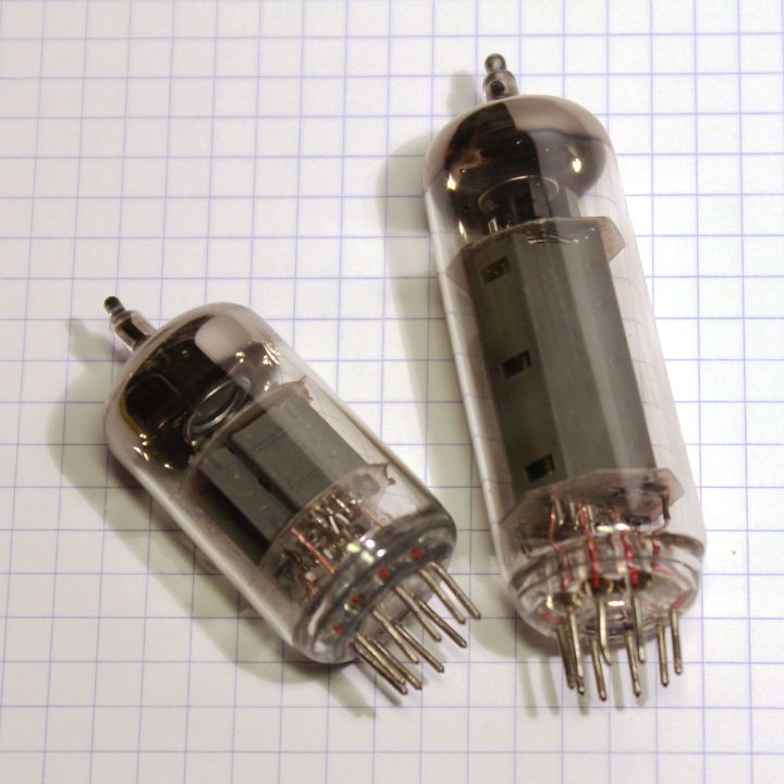
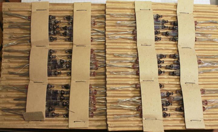
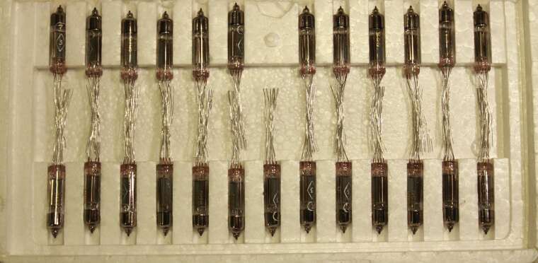
I looked on eBay to see how much they cost (as well as the "support" parts") and stumbled upon the younger russian siblings of the EL84... and couldn't resist buying a box of them !
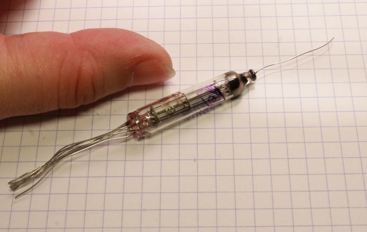
They're smaller, consume and emit less energy, don't need a socket, run faster at a lower voltage...
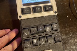
So what can I do with these ? Not much but we can cover the basics : combinatorial and sequential logic, build an adder with an accumulator for example, just like it all started with #SPDT16: 16-bits arithmetic unit with relays (let's stay safe).
The plan is to
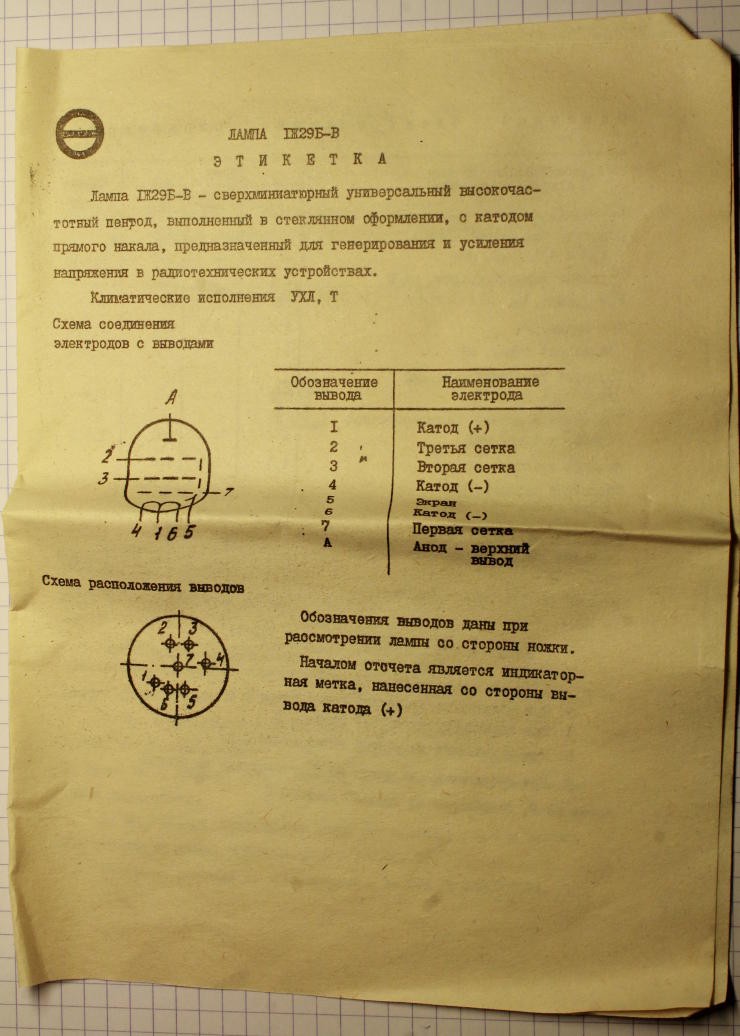
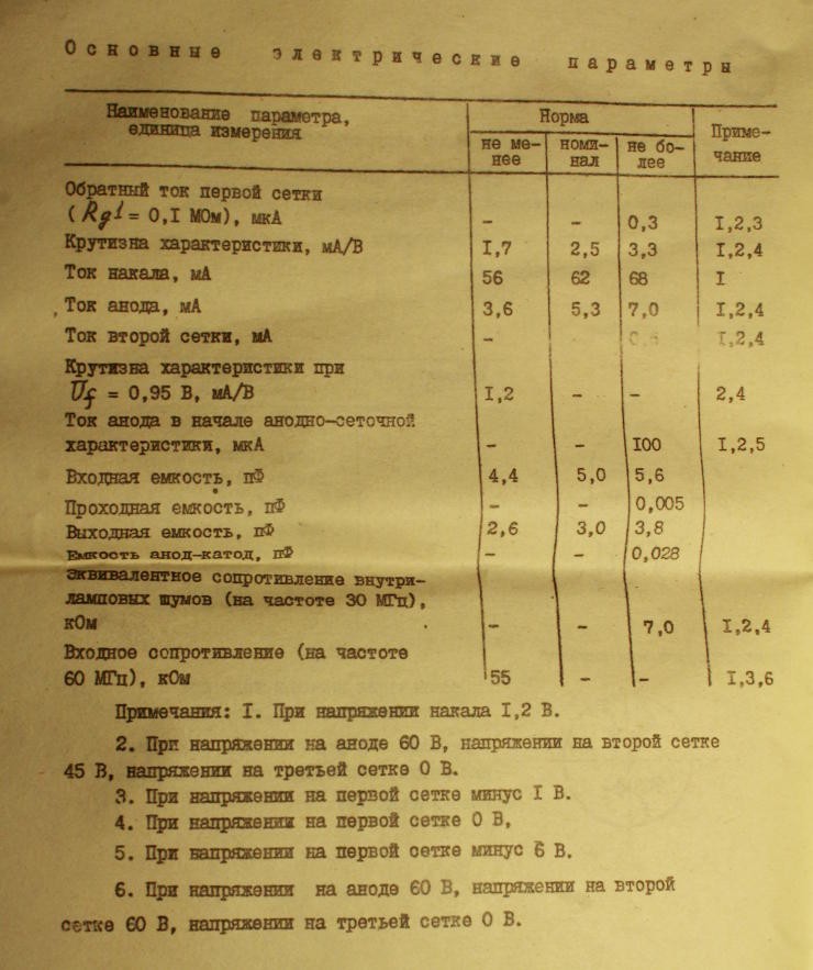
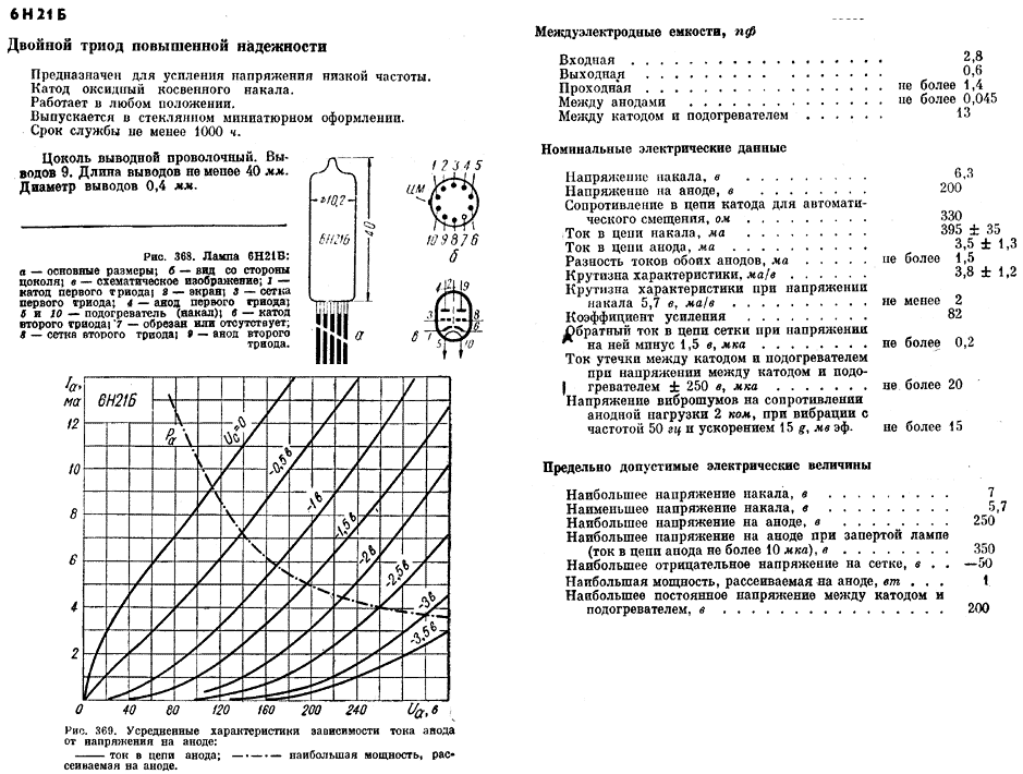
- characterize the 6N21 and 1J29
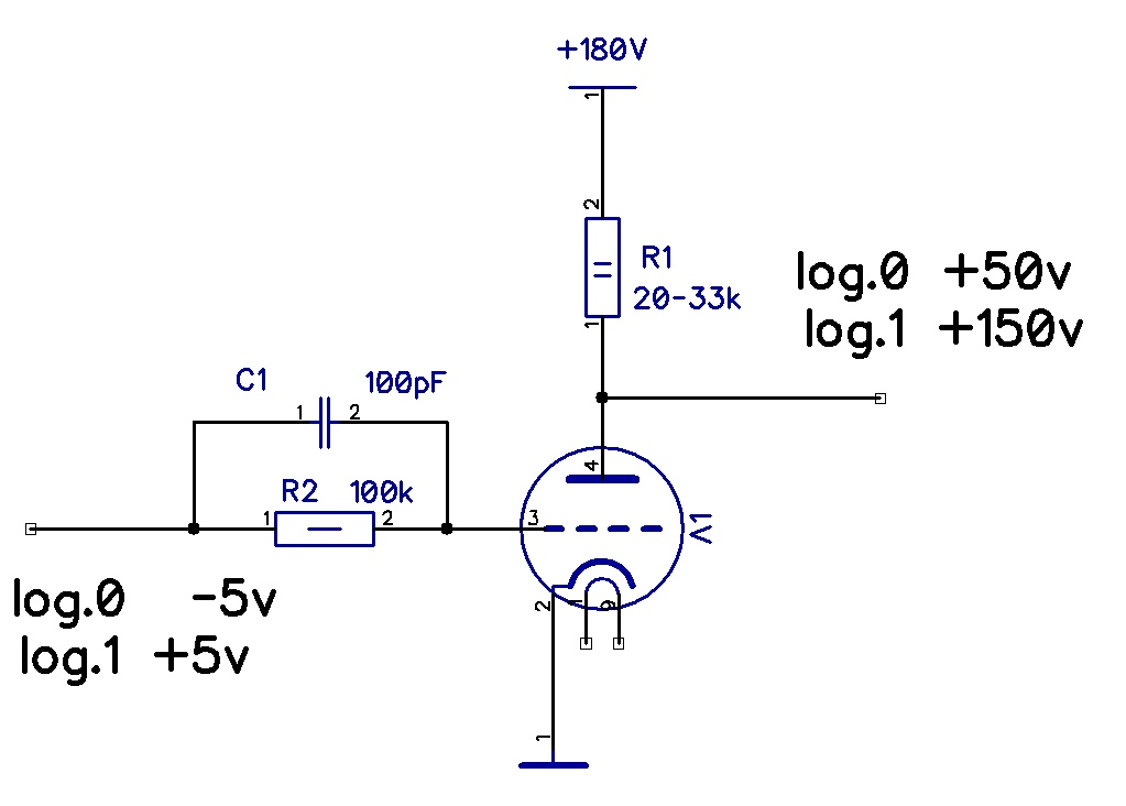
- make a few logic gates (maybe I can do AND gates with pentodes ?)
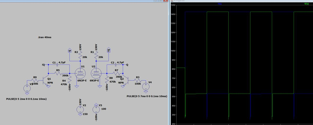
- make a flip-flop (the dual triode looks great for this purpose)
- make a half-adder and full-adder circuit
- chain the full-adders to make a 8-bits adder
That sounds so easy, right ? ;-)
Logs:
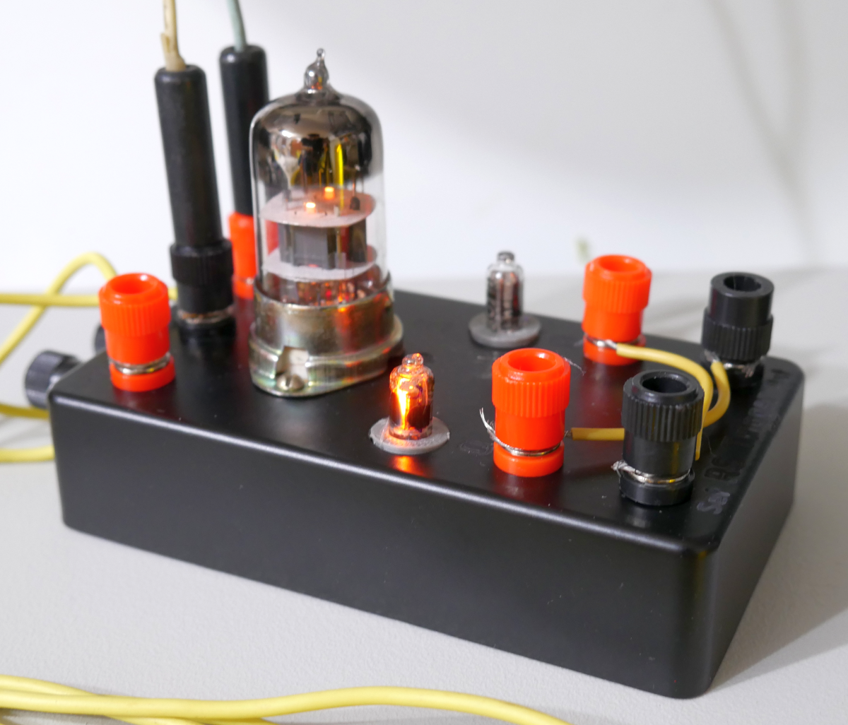
1. The 6Н21Б (6N21B) are cute !
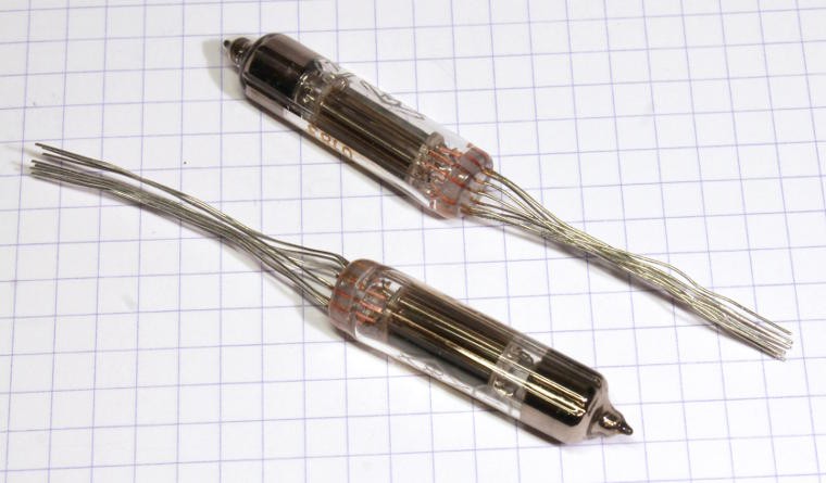
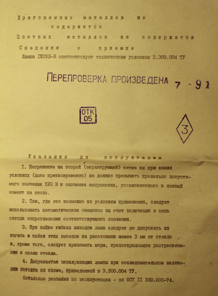
2. 1Ж29Б-В (1J29B-V) arrived too
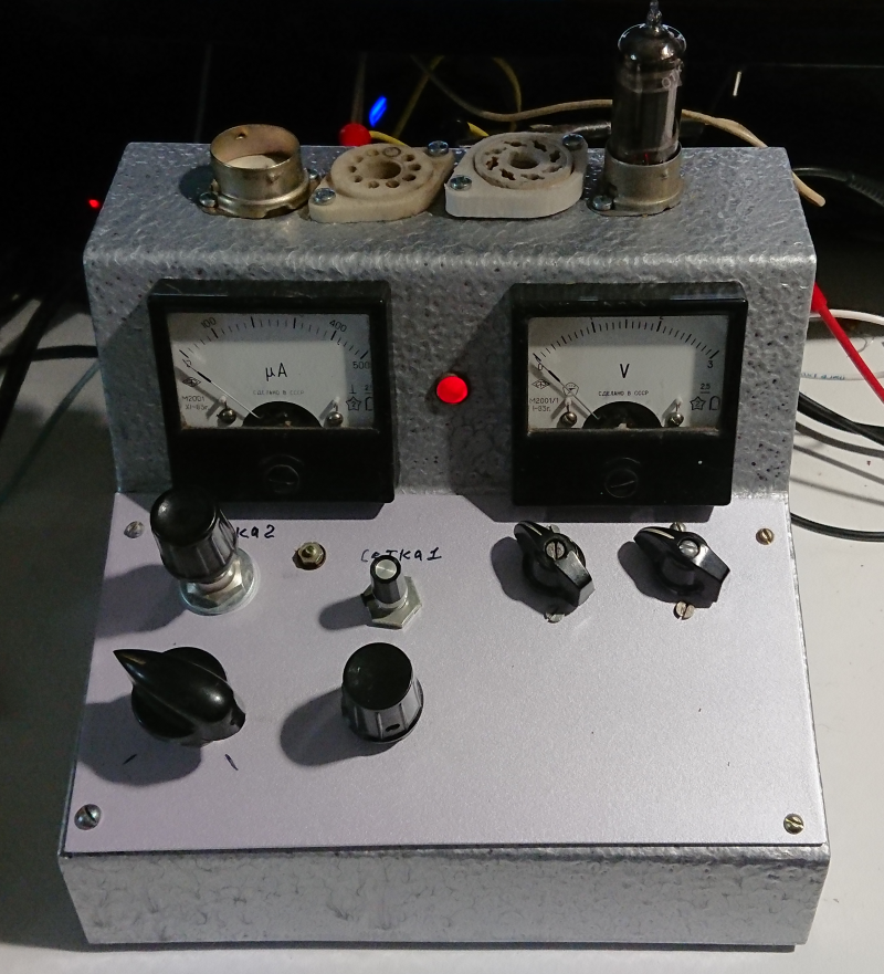
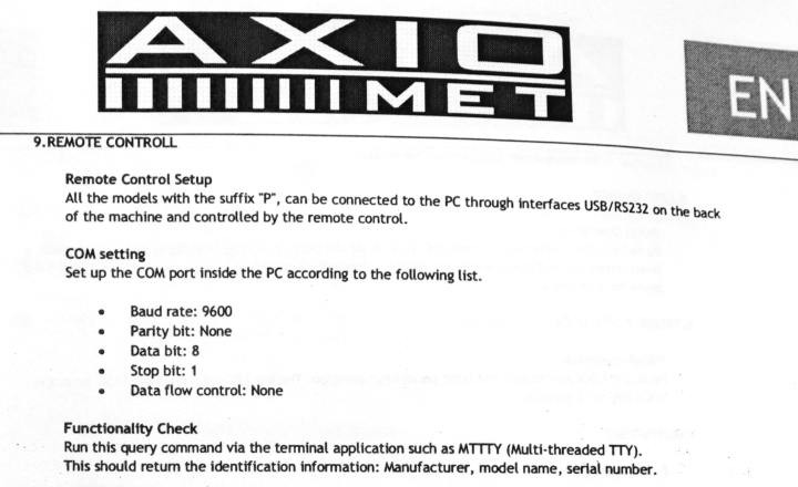
3. And the PSU
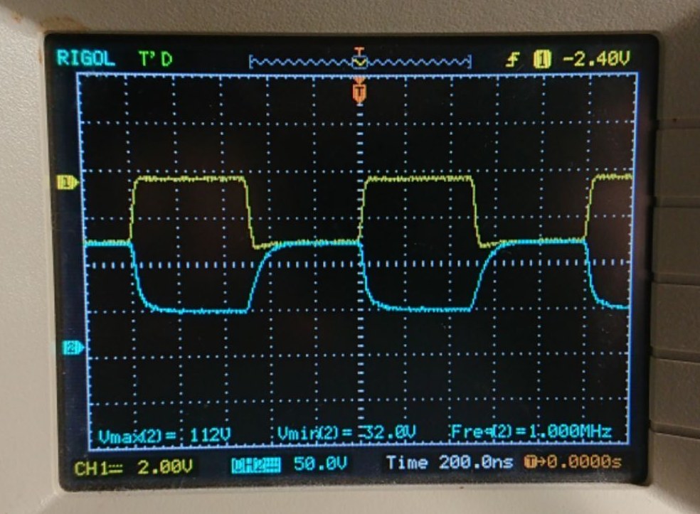
4. valve circuits
5. tube logic
6. Thank you
7. ENIAC and the FlipFlops
 What ?
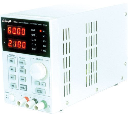


 John Duffy
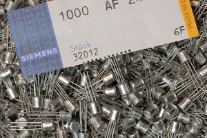

 Paul Andrews
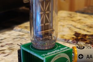
 hamster
@Artem Kashkanov I uploaded this video where I try to revive old russian electrolytic capacitors.
https://www.youtube.com/watch?v=Bryg2wDXm8o
Then I think I hear you mentioning ESR and capacitors in your video... Does that help ?