 Florian Festi
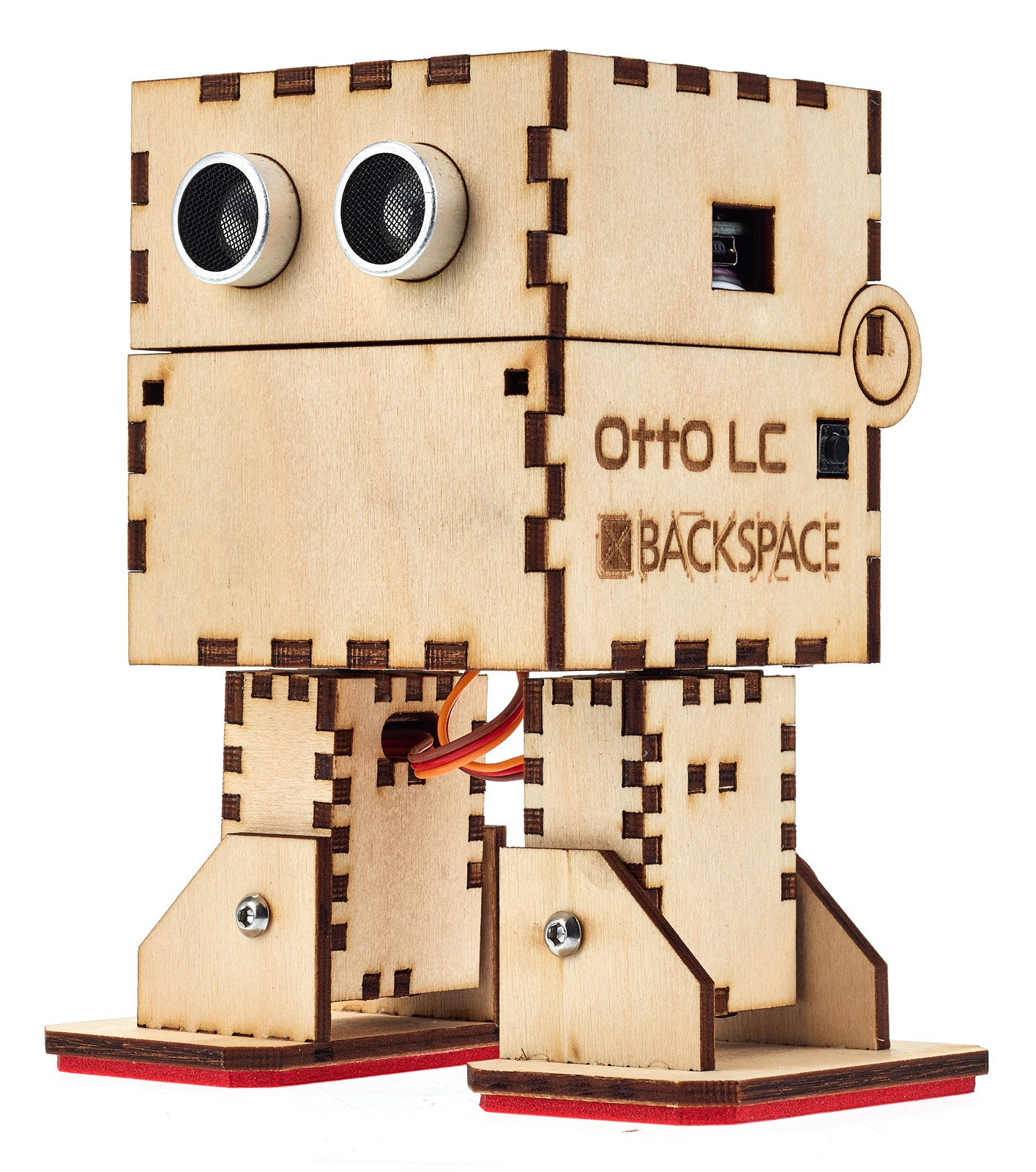
We wanted to do a robot project for children and found Otto DIY here on Hackaday. While it is a very nice project it uses a 3D printed chassis. While 3D printing is really cool for building one robot it just takes too long for 20 robots. As the chassis is basically made of 3 blocks plus the feet it was a natural step to recreate it in Boxes.py a software to create boxes on a laser cutter.
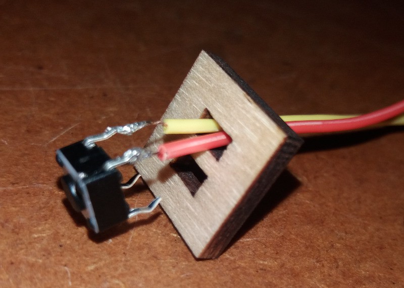
If cut with sufficient burn correction (aka kerf) most pieces can be put together without glue (but with significant force). This is nice for one robot but turned out to be not very practical for children who often lack the strength (unless you want to hand them a mallet).


 Volttherobot
 meatqueen
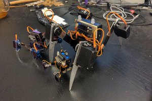
 deʃhipu
 OpenRomibo
I'd love a DXF file too. I'm a teacher and I'd love to be able to use this for my classes.