 davedarko
What is this good for?
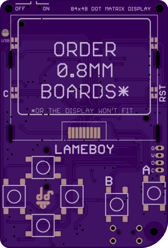
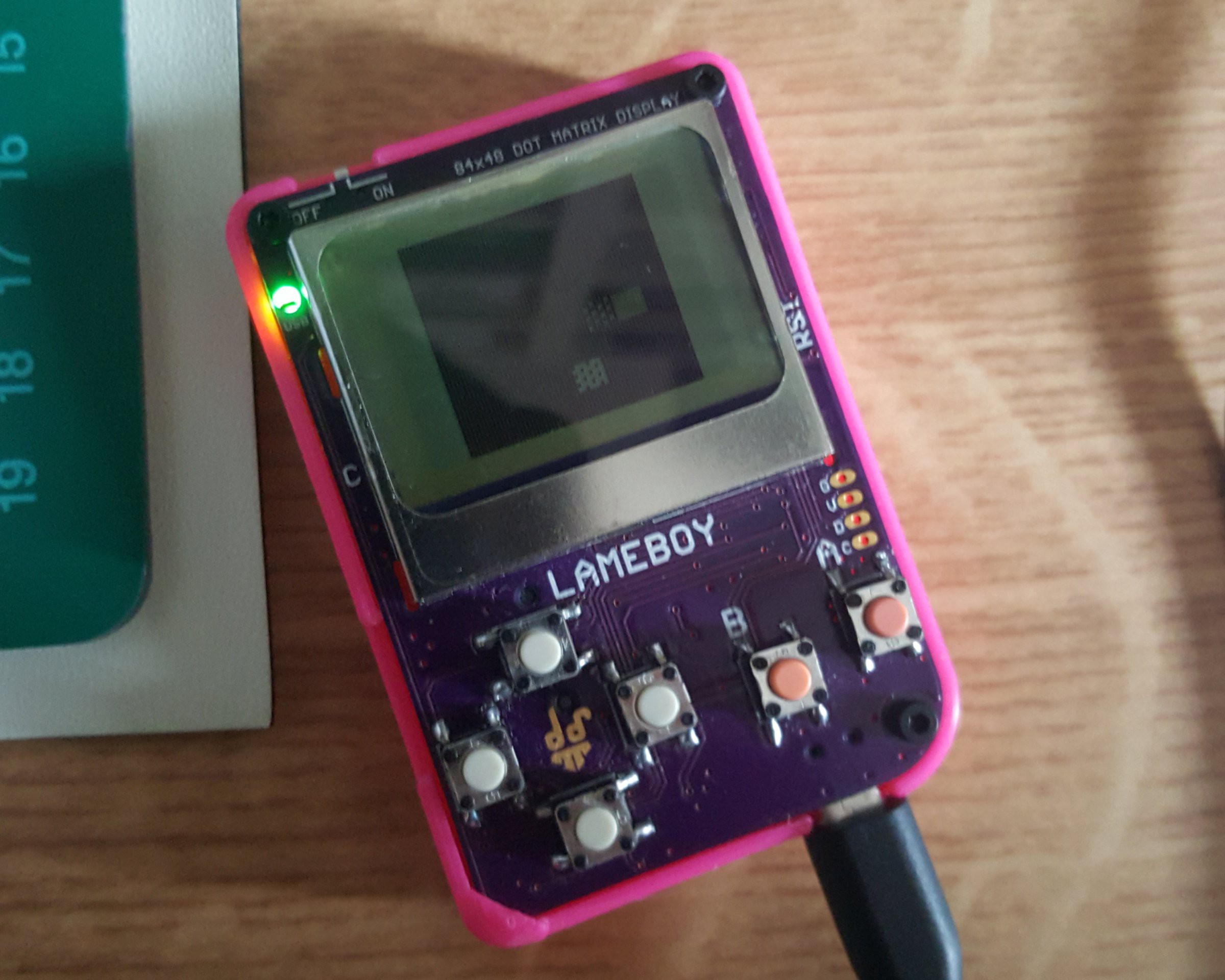
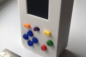
Ever needed an IoT remote to connect to all your MQTT stuff? Or wanted to check your hackaday.io likes? Maybe test your WiFi with the ESP8266? It's also good for gaming, as the looks might give away.
RGB background light might seem unnecessary at first, but in context and with some thought it's a good indicator for things. To save pins I'm throwing an attiny13/45/85 on the board to let a BlinkM clone handle the RGB controlling. https://code.google.com/archive/p/codalyze/downloads - firmware
On that I2C is also a PCF8574, an IO Expander that will scan the buttons for me.
There is a grove connector - basically almost a 2mm JST connector - that will allow me to add some sensors or another board that I'm working on for sound
#T85SID - I2C sound thing
https://playground.arduino.cc/Main/SIDuinoI2c
http://playground.arduino.cc/Main/SID-emulator
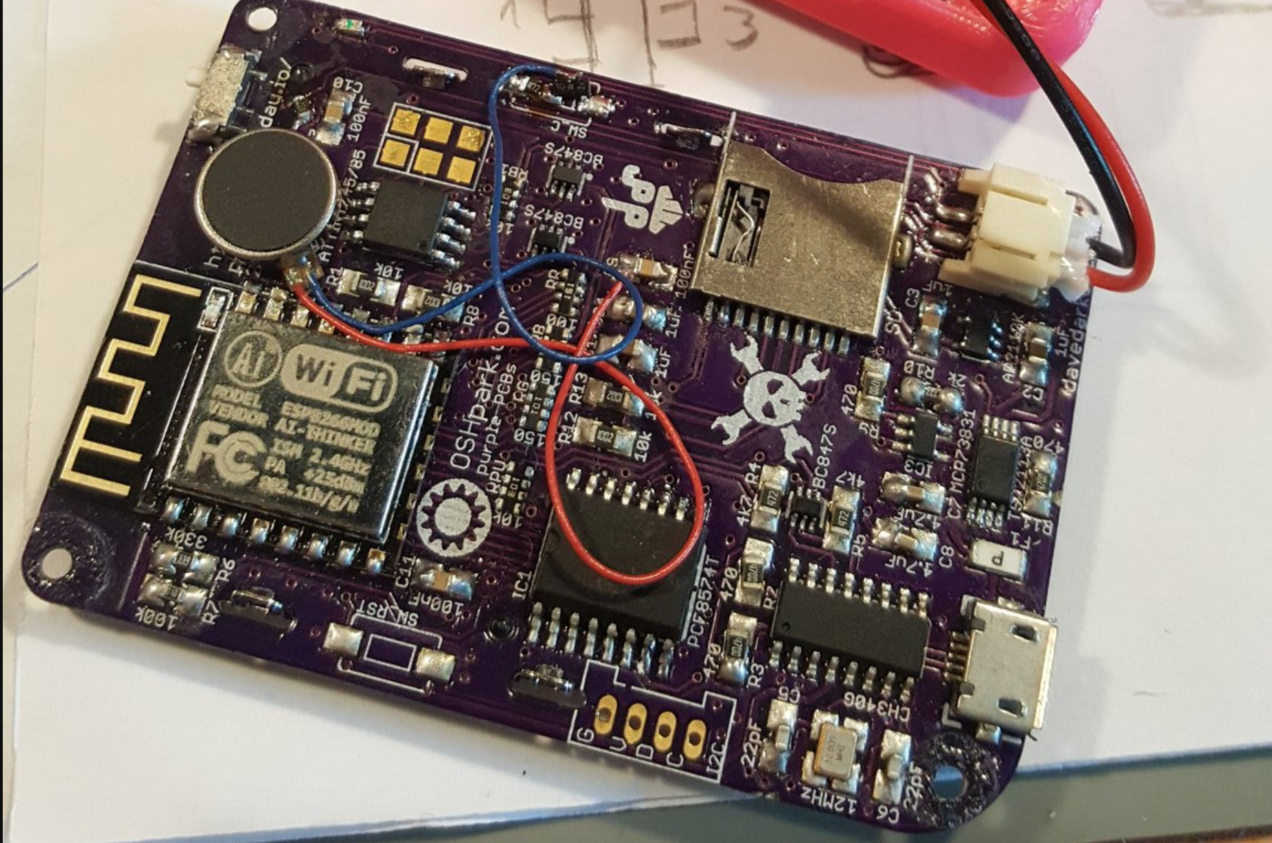
When it comes to power, I've wanted it all, meaning the board needs to be able to charge a LiPo with the help of an MCP73831 but also stay on when I plugin USB or remove it. For this I've integrated the TPS2113A, a power mux chip that does just that and keeps me from throwing in diodes at everything (that chip was also featured in a 3hours youtube live stream by David Watts - great watch!)
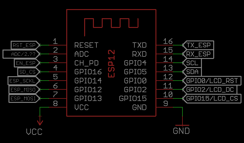
For connectivity I've copied from the known ESP breakout boards out there, that use the CH340G as a serial to USB converter and also a flip-flop circuit for pulling GPIO and RESET at the right time.
PCB change log R1 to R2
- changed every footprint from 0805/1206 to 0603
- updated footprint for I2C connecter (wrong dimensions in R1)
- moved the SD card further into the case (spoiler alert, too far)
- changed 1117-3.3 regulator to AP2112K
R2 to R3
- changed every footprint from 0603 to "onefitsall" -> 0603/0805/1206
- moved the SD card back out a bit
- moved side buttons further down between lcd slots
- moved LED for charging to a more familiar spot, shines through pcb
- added three decoupling caps
- corrected RGB LED layout and wiring error (RED and GREEN were mixed up)
- bigger footprint for crystal might improve hand soldering
- moarrr labelz
- [bug] Enable pin of ap2112k goes to the switch, other side is connected to VCC but should have been connected to regulator in
R3 (current) to R4 (WIP RC)
- changed USB micro footprint to fit more rigid version with through-hole fixing to the PCB
- adding soundstuff I still work on


 David Boucher
 lawnmowerlatte
 Dimitar
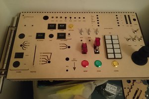
 Matthew Peverill
We have
https://universaljacket.com/shop/jason-derulo-yellow-jacket/