Close
0%
0%

Vision-Based Grasp Learning for Prosthetics

Building an intelligent, highly-functioning hand prosthetic on the cheap using the power of deep learning.

Similar projects worth following
This project is a hardware and software system to facilitate semi-automatic grasping of objects. So far, a hardware prototype as well as a low-level control API were developed that allows the hand to open and close. The hand prototype is of a five-finger anthropomorphic design to allow a range of objects to be grasped. A high level control algorithm using a Convolutional Neural Network was developed that is capable of predicting the use of each finger for grasping an object using visual information. This information is provided by a wrist-mounted camera that captures the object in relation to the hand. To train the network a dataset of 500 test images and servo positions was collated. At this stage the system is capable of successfully grasping objects with a rate of up to 92%.

I started this project as a final year EE student because I was curious about exploring the fields of Artificial Intelligence, Deep Learning and Machine Learning in general, as well as improve my electronics and CAD skills. But I wanted to create something that would one day be able to help people. This is how I became interested in creating a robotic hand that ultimately can be used as a prosthetic, but will also be suitable for more general automatic robotic grasping tasks. Given a very limited budget I decided to explore how far I can push functionality and intelligence of the hand with minimal sensory input. This is what led me to developing a hardware and software system that can make its own grasping choices based solemnly on visual input provided by webcam. The functionality of the hand is as follows in a nutshell:

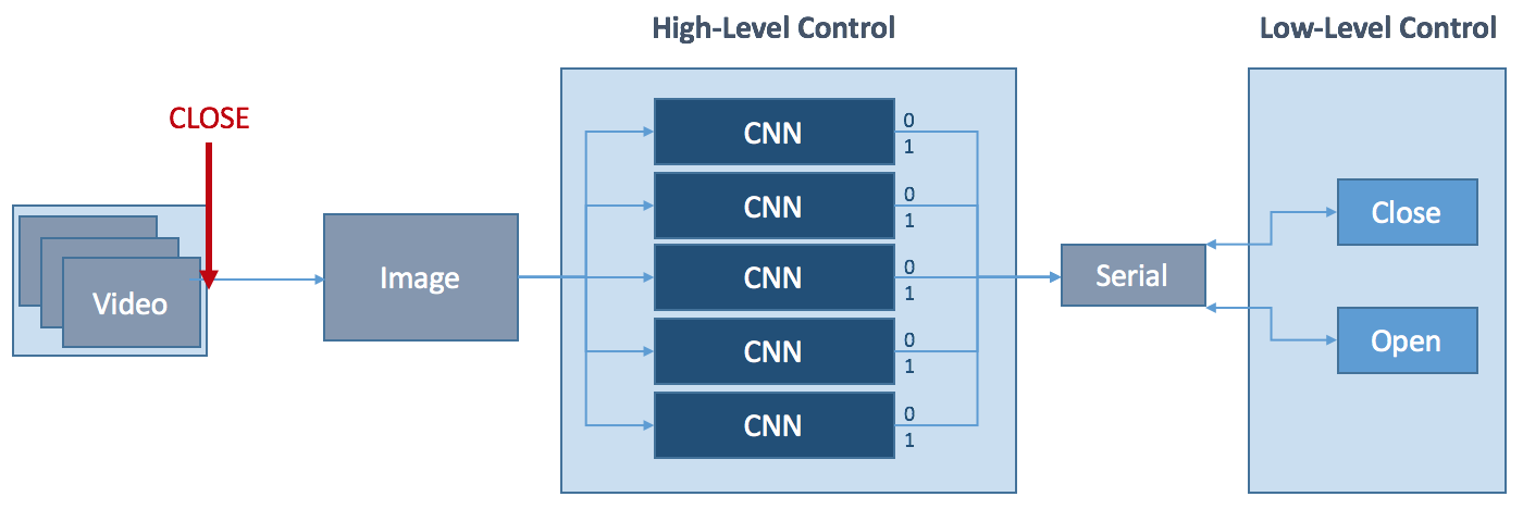
  • point the hand at any object, 
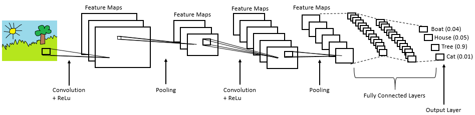
  • artificial intelligence via Convolutional Neural Networks decides the best way to grasp it,
  • prosthetic hand grips the object as instructed by the neural nets. 

The results so far have been incredibly promising as can be seen in the video below.

Licenses:

http://opencv.org/license.html

https://www.python.org/download/releases/2.7/license/

https://github.com/BVLC/caffe/blob/master/LICENSE

runHandMulti.py

Same as runHand but with one network rather than five.

x-python-script - 3.25 kB - 10/12/2017 at 20:49

Download

runHand.py

Python script that runs high-level control. Local paths will differ. You will need a lot of free memory to run this or an Nvidia GPU.

x-python-script - 4.02 kB - 09/01/2017 at 19:52

Download

run_demo.zip

Low-level API to run the hand.

Zip Archive - 2.32 kB - 08/27/2017 at 15:18

Download

lib_test.zip

Extended low-level API for data collection for training.

Zip Archive - 3.38 kB - 08/27/2017 at 15:18

Download

myhand.zip

All the STL parts to build and test the hand.

Zip Archive - 1.96 MB - 08/27/2017 at 12:05

Download

  • 1 × Arduino Mega 2560
  • 1 × Arduino Mega PCB Shield
  • 1 × PLA for 3D printing
  • 2 × 1mF Capacitor for smoothing
  • 5 × Servos with analogue feedback e.g. Batan S1213

View all 12 components

  • Combining Five CNNs into One

    Stephanie Stoll10/12/2017 at 20:37 0 comments

    As I mention in my previous log, performance could possibly be enhanced by combining the current five networks into one. This would allow to assess the use cases of each finger considering the whole hand rather than treating each finger independently. This could result in the network learning different types of grasps and avoiding unfortunate combinations. 

    The graphic below shows a simplified version of what I did: Each finger used to have its own CNN that would assess wether the finger would be used to grab the object in question or not, making it a binary classification problem of 'used' or 'not used'. For training this meant associating a label of either 1 (used) or 0 (not used) to each training image. In this case the label can be fed in directly as a number from a text file. For the combined network, the CNN's output was changed from binary to making a 'used' or 'not used' prediction for every finger, given one input image. This meant the last fully connected layer needed to be duplicated 5 times to assess each finger's use in relation to the others. This meant the labels for training changed from being binary to being a five-element vector of 1s and 0s, e.g. 11000 meaning 'use thumb, index, don't use middle, ring, and little finger'. To represent multi-label input I generated 5-pixel binary images with either 0 or 1 value for each pixel. 

    This is the graph of the combined network as visualised in Digits:

    The figure below shows the accuracy and loss for the combined network. Although accuracies for the index and middle finger went down overall accuracy increased across all fingers. 

    Grasp success for the glue stick object that was used for training, accuracy has improved to 92%. I will follow this up with a post showcasing results and also collect some grasping data for other objects the network has not been trained on. 

    The real success however is that the hand has learned to avoid strange finger combinations (like grabbing something with middle and little finger only) and now favours pinch grasps using thumb, index (and middle) finger, wrap grasps with index, middle, ring, (and little) finger, as well as grasps using all fingers. 

  • Current Results of Vision-Based Grasp Learning Algorithm

    Stephanie Stoll09/03/2017 at 14:22 0 comments

    This log presents and discusses the performance of the vision-based grasp learning algorithm used to control the hand prototype. Let's first examine the networks’ learning results before presenting and discussing the algorithm’s performance in grasping experiments using previously unseen test data. 

    Learning

    The five CNNS at the heart of the learning algorithm were trained using 500 images of a glue stick object in the vicinity of the hand prototype and positional feedback of the hand’s fingers after a grasp attempt.  

    The graphs below show accuracy and loss for the net controlling the index finger with two different sets of parameters. 


    a) is the accuracy and loss over 30 epochs using a stochastic gradient descent solver and a base learning rate of 0.01. Whereas the accuracy is very acceptable with 86%, the system does appear to not have converged entirely, and appears unstable. To allow the system to converge and stabilise the solver type was changed to Adam, and the base and learning rate set to 0.0001 (see b). The system was trained over 60 epochs, but this did not change values significantly, so it was later reversed to 30 epochs. 

    Let's look at all the accuracies and losses for all five CNNs:


    Accuracies for the thumb (a), index (b) and middle (c) finger are 80%. Compared to this the accuracy for the ring (d) and little (e) finger is poor with 63% and 72% respectively. This difference in performance could be due to the thumb, index and middle fingers having more defined use cases in wrap as well as pinch grasps, whereas there are less clear scenarios that would specifically require the ring or little finger to be used. 

    A higher amount of training and validation data would likely provide clearer and more meaningful results. However, the system still managed to learn queues to successfully grasp different objects as well as the object used in training as can be seen in the next section. 

    Grasping

    This section presents the performance of the vision-based grasp learning algorithm under similar conditions to the grasp data collection (halogen light, white background). The CNNs responsible for learning were trained on images of a glue stick, which was one of the objects tested in grasping tests. However, other objects were also tested, to assess whether the system has generalised. The other objects are a glue bottle, an iPhone 6s with case and cover, a roll of masking tape, a white golf ball, and a black golf ball. A successful grasp was defined as being able to grasp and hold the object stably for at least three seconds, or for no finger reacting if the object is out of reach. An unsuccessful grasp was defined as the hand not being able to grasp and/or hold the object for at least three seconds, or for one or multiple fingers reacting when the object is out of reach. Figures indicating the percentages of success and failure for each object over 100 grasp attempts each are summarised here:


    For the glue stick a success rate of 82% was found. Small and elongated objects such as the glue bottle and the pen out of the previously unseen objects performed almost equally well. This is possibly due to their similarity in shape to the glue stick. Small size makes it easier for the fingers to wrap around an object, which is possibly why the pen outperformed the glue stick in its success rate. This could however also be down to the relatively limited amount of data samples. An also elongated but bigger object like the phone was harder to grasp due to the fingers closing uniformly across their phalanges and therefore not being able to fully wrap around the object. Both golf balls’ performance was poor compared to all other objects. This was mainly due to the hand’s incapability to perform radial grasps, as this would require abduction of the fingers. Additionally, the white golf ball was hard to distinguish against a white background, further worsening performance.

    Overall, the success rates for grasping objects...

    Read more »

  • Data Collection and Training

    Stephanie Stoll09/01/2017 at 20:12 0 comments

    This log discusses how the CNNs where trained for my system and what data was used, as well as describing the data collection and augmentation process. 

    Five convolutional neural networks are at the heart of the high-level control of the hand prototype. In order to retrain the networks for the task of classifying a finger as used or not used in a grasp attempt a dataset needed to be created for training and validation. Given time constraints only 500 grasp attempts were recorded but I hope to increase that number significantly and see what difference it makes on the performance of the system. 

    I will now look at the nature of the data, how it was collected and augmented and how it was used to train the five CNNs. 

    Data Collection and Augmentation

    The data for the grasp attempts was collected from the hand’s sensory system consisting of a wrist camera and feedback sensors from the five servos controlling the hand. For each grasp attempt a still image was recorded of the hand in its open position and an object in its vicinity. The hand is then closed and the normalised feedback values of each finger are recorded and used as labels. The labels act as the ground truth in the training of the CNNs. The feedback values allowed us to measure if a finger had encountered resistance and therefore made contact with the object or whether it had fully closed and therefore was not part of the grasp. The figure below shows data examples for two different grasp attempts:

    Data Collection Process

    In total 500 grasp samples were collected over two days under similar conditions and using the same set up. To keep lighting conditions as constant as possible data collection took place indoors, using only artificial halogen light. The hand was placed in a sideways position (see below, and a white background placed behind the hand’s fingers, to minimise influence of any background features on the network’s learning process. 

    The object to be grasped was a glue stick, as its cylindrical shape lends itself to different grasp types like pinch and wrap grasps. The stick was manually placed into position, but a python script was written to automate as much of the data collection process as possible in order to minimise human interaction altering the data. The script contains the following steps:

    1. set up camera, establish serial connection to Arduino.

    2. set up and calibrate the hand.

    3. Stream video to screen whilst positioning object.

    4. Confirm by keypress when object is in position, record current frame.

    5. Close hand using feedback mechanism.

    6. When all fingers have reached their end positions, record positions as labels to frame.

    7. Open hand.

    8. Go back to 3. 

    9. Re-calibrate hand after 20 grasp attempts.

    The raw data collected consists of one frame per grasp attempt and a text file listing full paths to all images and their corresponding labels.

    The following section describes how this data was formatted and augmented to be used to train the five CNNs that control the hand’s fingers. 

    Data Formatting and Augmentation

    he raw data collected needed to be formatted to be used in DIGITS, NVidia’s Deep Learning GPU Training System for Caffe. A separate dataset was created for each of the five networks. Each dataset is described by a text file with full paths to each image and the label belonging to the finger in question. The labels are quantised into two stages 0 and 1, signifying the two classes ‘used’ and ‘not used’. Each dataset was then balanced between positive and negative training examples. For all fingers apart from the thumb, this meant increasing the number of negative examples by duplication. The number of positive examples for the thumb (meaning the thumb being involved in the grasp) was significantly lower than for the other fingers, hence positive training examples...

    Read more »

  • CNN-based High-Level Control

    Stephanie Stoll09/01/2017 at 19:44 0 comments

    This log goes into detail about the implementation of the high level control. For a reminder on what the system looks like on a more basic level see a previous log called Introduction to Vision-Based Learning.

    Combining Caffe, OpenCV, and Arduino

    A Python script combines the Caffe-trained AlexNets, the OpenCV camera feed and communication with the Arduino Mega 2560. This script is used to control the hand from the command line giving only a closing command. The open command is issued automatically but this could be easily changed to manual operation. The script demonstrates the simplicity of the hand’s interface, with most of the complex work carried out by the CNNs. You can find the script under files.

    Let's look more closely at how Caffe defines CNNs and how data is processed. 

    CNNs in Caffe

    In Caffe deep networks are defined layer-by-layer in a bottom-to-top fashion, starting at input data and ending at loss. Data flows through the network as blobs in forward and backward passes. A blob is Caffe’s unified data representation wrapper. A blob is a multi-dimensional array with synchronisation abilities to allow for processing on the CPU as well as GPUs, that can hold different kinds of data, such as image batches, or model parameters. Normally, blobs for image data are 4D, with batch-size x number-of-channels x height-of-images x width-of-images.

    Blobs are processed in layers. A layer inputs through bottom connections and outputs through top connections. Below shows the definition of a convolution layer in plaintext modelling language on the right, and visualised as a directed acyclic graph (DAG) on the left:

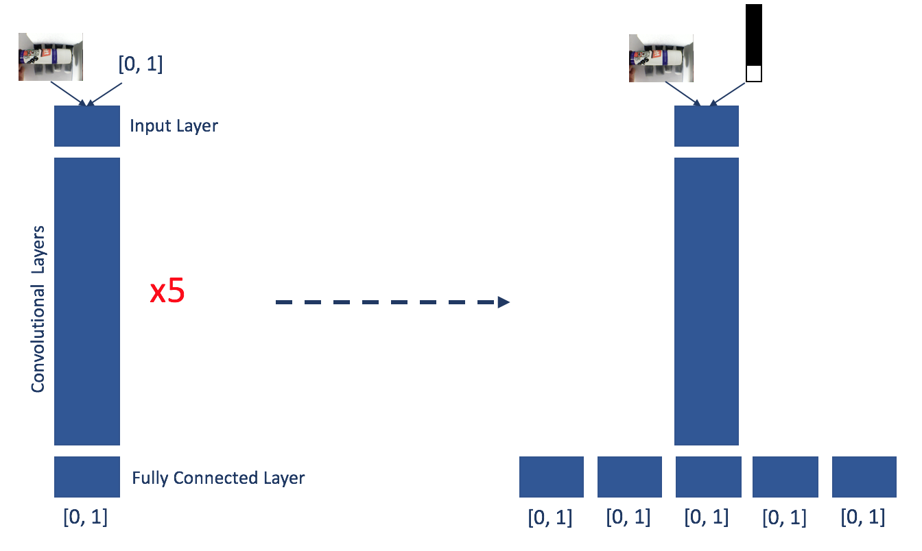
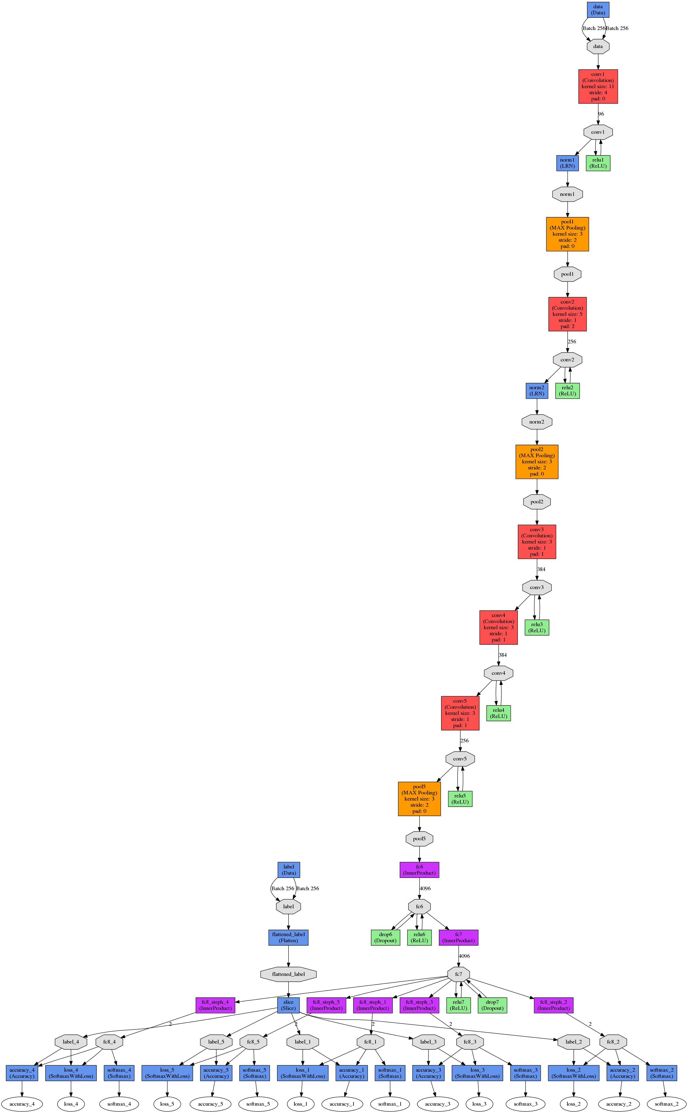
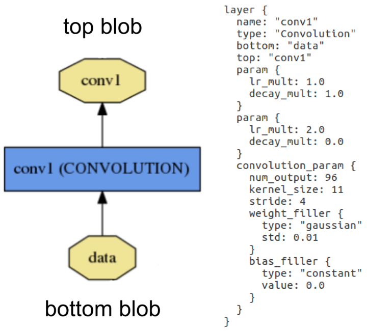
    Layer example: Layer "conv1" takes in data through bottom connection and outputs conv1 through top connection. Parameters for convolution operation are defined in the net's prototxt file and can be visualised as a DAG (directed acyclic graph).

    Layers are responsible for all computations, such as convolution, pooling, or normalisation. A set of layers and their connections make up a net. A net is defined in its prototxt file using a plaintext modelling language. Normally, a net begins with a data layer, that loads in the data and ends with a loss layer that computes the result (classification in our case). The weights for the net are adjusted in training and are saved in caffemodel files. 

    The figure below shows a DAG visualisation of Yann LeCun’s LeNet-5. In this case, the network is configured to train in batches of 64 images. Images are scaled before being put through the first convolution stage. The first convolution stage has an output of 20 per image. The outputs are pooled using max-pooling before being put through the second convolution stage with 50 outputs per image, followed by another pooling stage. Data then enters the fully connected layers, in which the first inner product layer computes the inner product between the input vector and the weights vector with an added bias, producing 500 outputs that are then rectified using a sigmoid. This output is fed into a second inner product layer which produces an automatically calculated number of outputs (or it can be defined in the prototxt file). Finally, loss and accuracy are computed by comparing the results of the second inner product (ip2) to the labels, whereas softmax reflects the likelihoods of each class computed in ip2. 

    LeNet-5 was developed for character recognition and works on small 28x28 pixel images. It was only used in this project to understand the fundamental principles of deep networks. For our high-level control, we used five instances of a pre- trained AlexNet which was designed in 2012 for the ImageNet Large-Scale Visual Recognition Competition (ILSVRC). 

    AlexNet

    The AlexNet architecture is similar to the LeNet but more complex. It has five convolutional and three fully connected layers and randomly crops 224x224 patches from an input image, meaning effectively less data is needed. AlexNet contains 650,000 neurons, 60,000,000 parameters...

    Read more »

  • Convolutional Neural Networks and Caffe

    Stephanie Stoll08/28/2017 at 10:16 0 comments

    A bit on Neural Networks in General

    There has been an increasing trend to use Artificial Neural Networks (ANNs) for solving problems in a variety of fields, such as classification, compression and other data processing, control, and robotics. They are loosely based on the human nervous system, in the way it consists of a high number of simple, yet highly interconnected units (neurons) working together to solve problems. ANNs first gained popularity in the late 1980s/ early 1990s, however, their use cases were limited due to the relatively small computational resources at the time. In the last few years ANNs have experienced a renaissance as computational power has increased dramatically. Today they are an integral part in solving many data based problems. 

    Convolutional Neural Networks

    CNNs are the type of neural network most commonly used for computer vision problems. Let's look at a simplified representation of a CNN architecture called LeNet: 


    A CNN can have different architectures but always includes the following steps: 

    1. Convolution 

    2. Non-Linearity (Rectified Linear Unit) 

    3. Pooling (Sub Sampling) 

     4. Classification (Fully Connected Layer) 

    In the convolution stage the input image is convolved with a range of filters. The filters are the weights adjusted in training. The resulting feature maps are rectified by setting all negative pixel values to zero using the Rectified Linear Unit (ReLu) operation. In the pooling or sub-sampling step the dimensionality of the rectified feature maps is reduced whilst retaining important information. This makes the feature maps less computationally expensive and less susceptible to scale and translation. Convolution, rectification, and pooling steps can be repeated multiple times, extracting features from an input image. In the fully connected layer the extracted features are used for classification.

    After looking at the structural elements of a CNN, it is necessary to define what is meant by ‘training a network’. Training takes place in two directions through the network, with feedforward and backpropagation: In training, data is fed through the network in a forward manner, resulting in an output at the output layer. This output is compared against the ground truth (the expected values) and a total error is calculated. The error is then backpropagated through all the layers from the output layer to the input layer, adjusting the weights (filters) depending on how much they account for the total error at the output. The feedforward and backpropagation process is repeated ideally until all weights are stable. In other words, a set of weights needs to be found iteratively that minimises the cost function associated with the total error of the network, causing the network to make better predictions over time. 

    Tools for using Neural Networks

    Due to deep learning’s recent popularity, there are several frameworks and libraries available for building and utilising neural networks. Let's look at some of the most popular.

    ‘Caffe’ is a deep learning framework developed by Berkeley Artificial Intelligence Research at the University of California, Berkeley. It is written in C++ but has interfaces for Matlab, the command line as well as Python. Data is processed in N-dimensional arrays called Blobs. They are passed between layers, which are responsible for all computations, like convolution, pooling and inner products. A net consists of a connected set of layers. NVidia’s Deep Learning GPU Training System (DIGITS) provides a powerful browser-based interface to Caffe. It has facilities for creating databases, as well as training, designing, and visualising neural networks. There is also a choice of pre-trained models such as AlexNet and GoogleLeNet available for use. 

    Another deep learning framework is ‘Torch’, developed and maintained by researchers at Facebook AI Research, Twitter, and Google DeepMind. It is based on C/CUDA but has a LuaJIT interface....

    Read more »

  • Intro to Vision-Based Learning

    Stephanie Stoll08/28/2017 at 09:57 0 comments

    This log is introducing the development process and methods employed for creating a software control system for the hand prototype. The high-level control software’s aim is to make its own grasping choices, requiring only minimal human input. The grasp choice is then sent to the hand prototype’s previously discussed low-level API in order to be translated into motor commands. In later logs I will discuss the usage of Convolutional Neural Networks in the high-level control, as well as the data used to train the CNNs. 

    Design Considerations

    One of the goals of this project is to significantly reduce the human input needed to operate the hand. Therefore, the control software should be able to operate on a minimal control signal of ‘open’ or ‘close hand’.

    Given the low-cost nature of the hardware the sensory information is limited. The control software needs to make maximum use of this data, which I think can be achieved by employing deep learning strategies.

    To make the control software reusable for other prosthetics it should be modular, adaptable and extendable. Given the training-based nature of neural networks in  the high-level control, the system could be retrained with a different prosthetic hand, the number of fingers could be reduced or expanded, and the concept of using deep learning even be applied to different types of prosthetics. 

    System Overview

    The figure below shows a simplified diagram of the hand’s software control system. The wrist-mounted camera continuously captures frames until interrupted by an external control signal, initiating the closing process of the hand. The frame captured by the camera at this moment is pushed through five convolutional neural networks (one for each finger). Each CNN has a two-class classification output. If the network returns 0, the respective finger is not used for the grasp, if it returns 1, it is used. 


    The resulting Boolean vector is passed on to the low-level control together with the closing command via serial connection. The hand then performs a grasp using the activated fingers. The opening of the hand can be initialised at any stage using an external opening control signal. 

    Something to change in the future is to replace the five individual CNNs with one CNN that can establish relationships between the different fingers, learning about which combination of fingers are favourable. It will be interesting to see how this changes the hand's performance. 

    Implementation Details

    The high-level control software is written in Python and combines the CNNs, the camera feed, and the Arduino Mega 2560 into one application that can be run in the command line. A simplified overview of the complete high-level control system can be found here:


    After setting up the Arduino, camera, and Caffe (a deep learning framework, more on that later), an ‘open hand’ command is sent to the low-level control of the hand. The low-level control sends a response back to the high-level control once the hand is opened. At this point the camera starts to stream frames to the computer screen. This allows for an object to be moved into the desired position before calling the ‘close hand’ command. This triggers for the current frame to be pushed into the five finger nets to determine whether a finger will be used for the following grasp attempt or not. The result of each network is collected in a vector and sent to the low-level control with the closing command. The closing command is executed with the appropriate fingers and a response is sent to the high-level control once the hand has closed. 

    In the next log I will attempt an explanation of what a CNN is, as well as introducing Caffe, the deep learning framework I used. 

  • Examining the Current Hand Prototype

    Stephanie Stoll08/27/2017 at 16:31 0 comments

    Let's look at the functionality for both the physical hand prototype, as well as its low- level control API. Firstly, I will talk about the hand prototype’s design, cost, ability, and stability before discussing the low-level API’s design and performance. 

    The Hand Prototype

    The robotic hand prototype was designed as a very simplified version of the human hand. Designing and building a robotic hand that approximates the dexterity of the human hand would have been great but frankly impossible due to budget constraints and this so far being an individual project. The prototype built is much simpler, but has enough dexterity to collect meaningful data and perform basic grasping operations. 

    The hand has five fingers, and five degrees of freedom. Force is transmitted through tendons using a Bowden system from five servo motors:

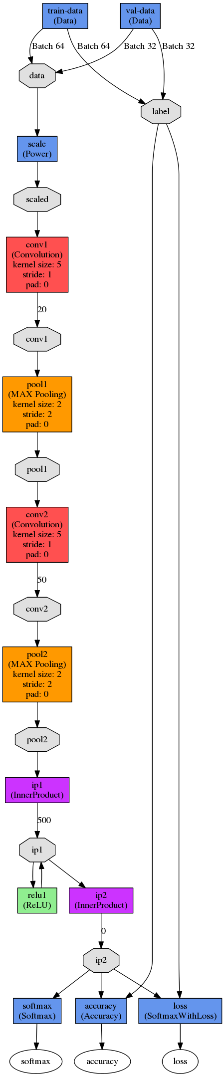
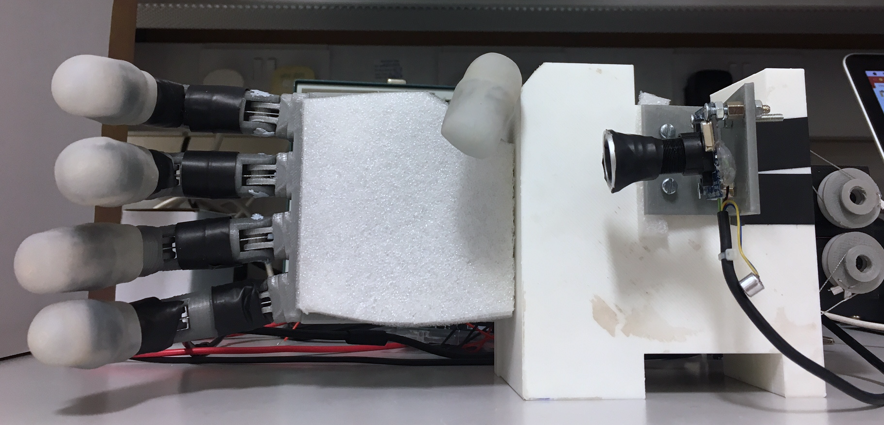
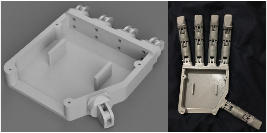
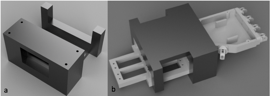
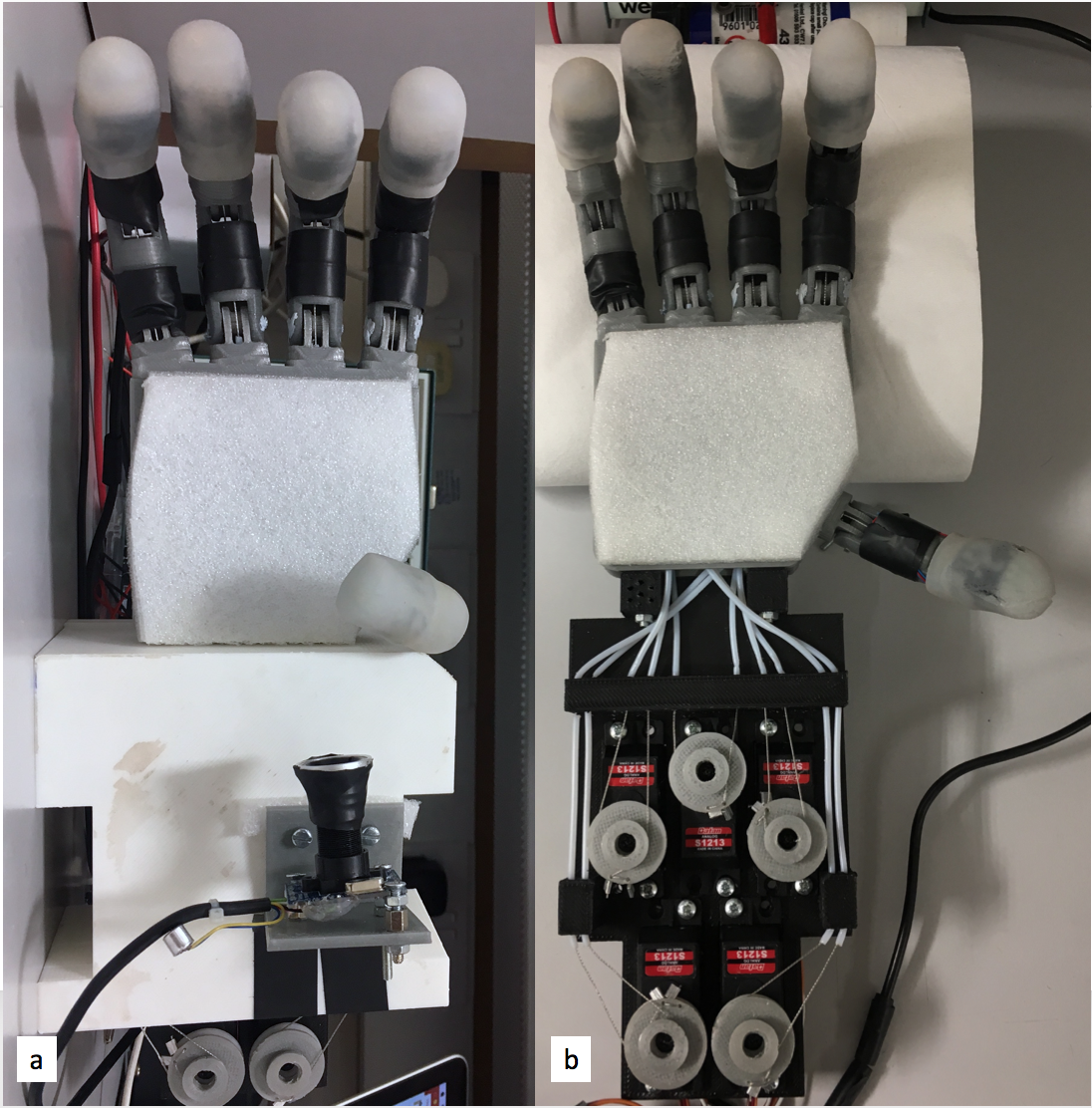
    The fully assembled hand prototype with mounted camera and servo bed cover(a), the hand prototype with servo bed cover and camera removed to give view to the actuator and tendon system (b).


    In its full assembly the hand weighs 655g. 

    The overall cost of the hand is estimated at £170 (see Table below for a break down). This makes it an incredibly cheap smart prosthetic/robotic hand. 

    Flexibility and Ability

    The tendon-based transmission system allows for the fingers to flex and extend, but not for abduction/adduction, hyper-extension, or individual control of any of the fingers’ phalanges:

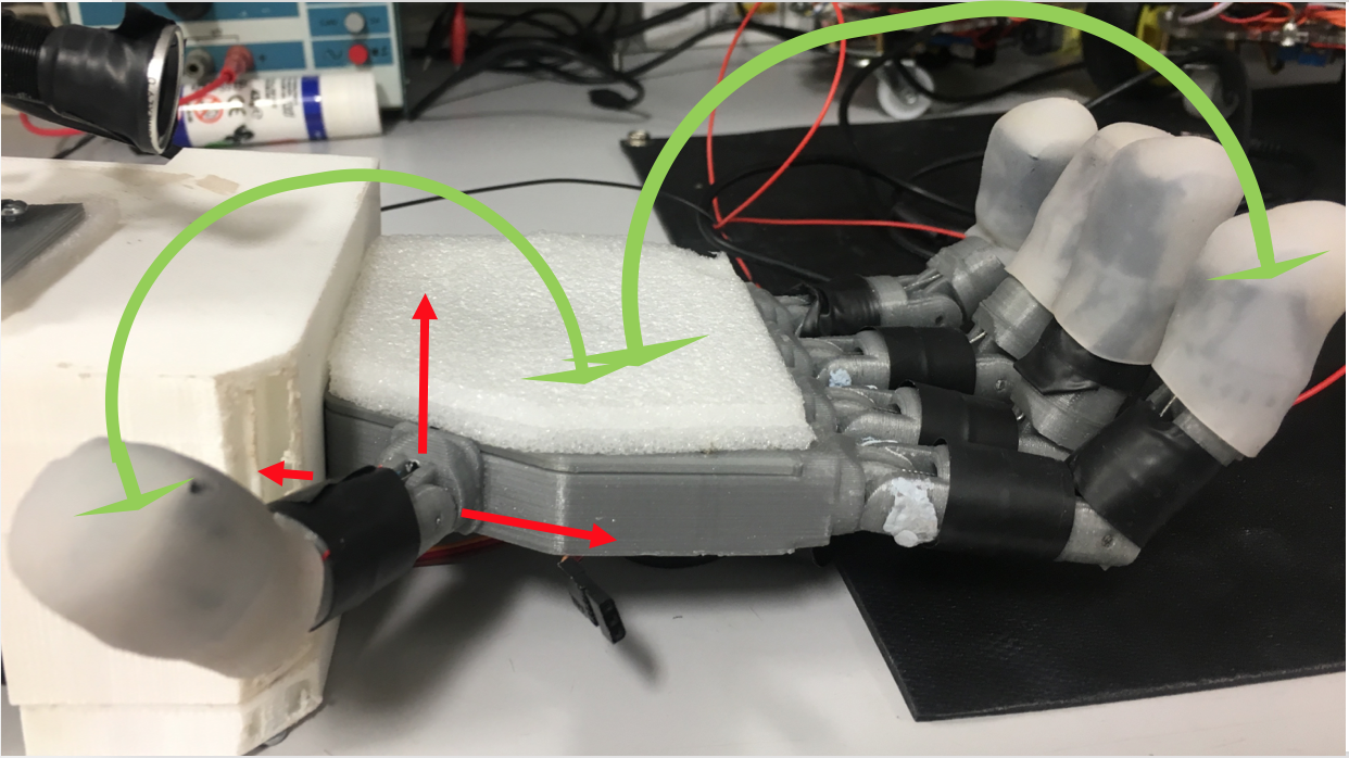
    All fingers are able of flexion and extension (indicated by green arrows for thumb and index), but not of abduction, adduction, neither radial nor palmar (indicated for the thumb in red).

    This limits the use of the thumb, compared to a human thumb in its dexterity. The robotic thumb is placed in a position that allows it to perform pinch grasps in conjunction with the index and/or the middle finger, but not with any of the other possible fingers:

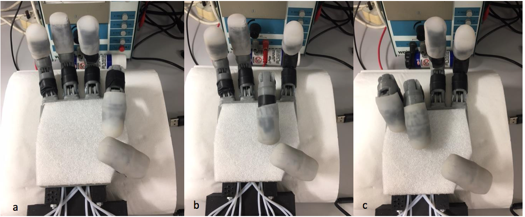
    The opposability of the thumb is limited to being able to perform pinch grasps with the index (a) and the middle finger (b), but not with the ring or little finger (c).

    This makes it a compromise between what was achievable to design given the limited amount of time and a fully opposed thumb. In our tests the hand was able to perform both precision and power prismatic grasps (wrap and pinch). 

    Stability

    Payloads of up to 220g where tested which is just over a third of the hand prototype’s overall weight. Higher weights need to be tested in the future. Apart from tendons, no parts of the prototype had to be replaced so far. Tendons are prone to snapping due to wear and tear or when too much pressure is applied to an object. However, they are low-cost and easy to replace. 

    Comparison to Human Hand

    The hand prototype is slightly larger than an average female hand and has a similar form factor to an average human hand. All fingers are spaced out and angled in a way that resembles a human hand in a relaxed open position, apart from the thumb, which is angled to approximate an opposed thumb:

    Performance of Low-level API

    The low-level API manages to reliably communicate with the underlying hardware by translating external opening and closing commands into motor control signals. The hand is able to open and close using the appropriate fingers specified by the input command.

    The extended low-level API is capable of collecting and using servo feedback data. The feedback is used reliably to stop fingers from closing when they exceeded their resistance by making contact with an object. This protects the servo motors, the object in question, and the hand itself from damage. It also allows us to estimate each servo’s actual position. The collection of this information was an integral part of collecting ground truth for the data used to train the Convolutional Neural Networks that form the centre of the hand prototype’s high-level control.

    The low-level API provides a simple interface to operate the hand, by using only two main functions (open_Hand and close_Hand). 

    In the...

    Read more »

  • Designing and Building a Hand Prototype Part 3

    Stephanie Stoll08/27/2017 at 15:11 0 comments

    In here I will talk about the low-level control API I wrote to run the hand and the API to collect training data to be used to train the CNNs at the heart of the high-level control.

    The low-level API controlling the hand's servos is completely detached from the high-level control making the grasping choices, their only connection being a serial line. This means the hand prototype could be used for any kind of robotic grasping application and the high-level control could easily be modified to work with a different piece of hardware. I will discuss the high-level control at a later stage, so for now let's look at the low-level control.

    Low-Level Control API

    The low-level control API was written in Arduino C/C++ and is based around the Arduino Servo library. The API consists of two classes, Finger and Hand:

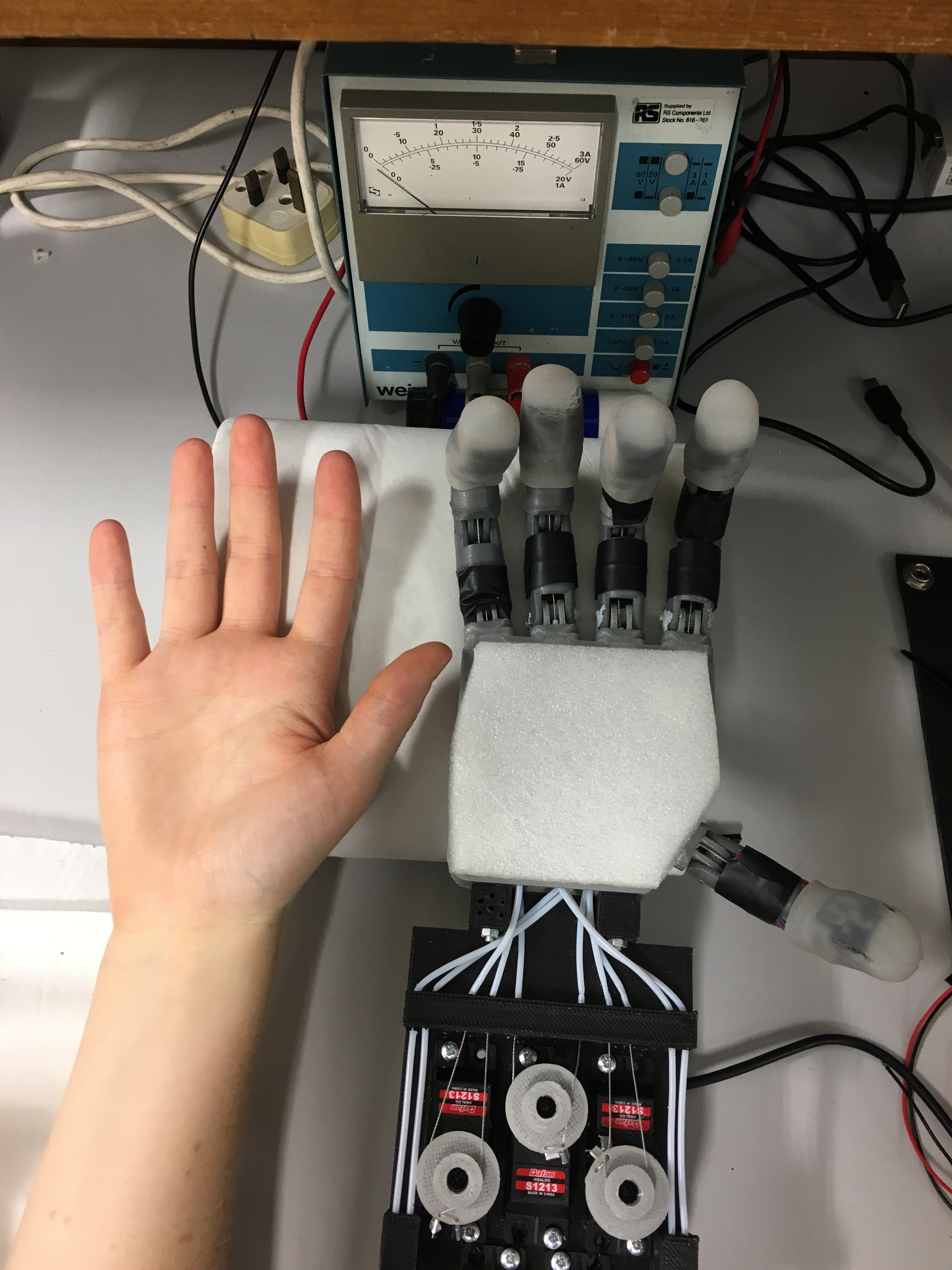
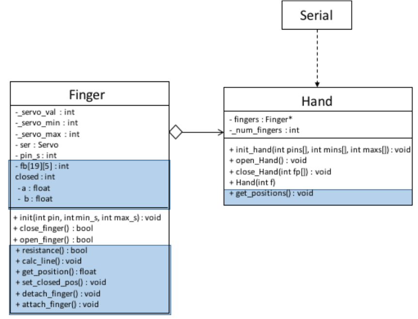
    UML diagram of low-level API. Parts of the extended API used to collect training data are marked in blue.

    A hand is created by giving the number of fingers (with a maximum of five). The constructor of Hand then creates the number of fingers specified and puts them into the fingers array. The Hand then requires the pin numbers each finger is connected to on the Arduino, as well as the minimum and maximum servo values for each. This is necessary to assure that no servo is overdriven, snapping a tendon. These values are passed on to the appropriate fingers. A finger is initialised by attaching and setting up an instance of Arduino Servo. The hand can then be opened and closed by calling open_Hand() and close_Hand(int fp[]), the latter requiring the array of activated and inactivated fingers from the high-level control. Open_Hand() and close_Hand() then call the open and close functions of each activated finger. 

    All communication between the high and low level control takes place via serial. The Arduino Mega 2560 has four hardware serial ports, of which one is connected to the USB device port via a USB-TTL Serial converter. This allows for communication between the Arduino IDE and the Arduino Mega 2560 via USB, for example when uploading sketches or using the IDE’s serial monitor. But the USB connection can also be used as a serial port between the Arduino and another application, in this case the python-based high-level control. On Linux and OSX the board is recognised as a virtual COM port automatically.

    On the Arduino’s side, serial communication is handled by the Arduino Serial library, which has facilities for setting up, reading from and writing to the serial port. Python’s pySerial library is responsible for communicating from the high-level control to the Arduino. In order for the two sides to communicate, their serial baud rates need to be matched. The baud rate sets the speed with which data is sent via serial in bits-per-second. In our system, the baud rate is set to 115200 bps, as this is fast enough for the task at hand (pun intended) whilst keeping transmissions stable.

    Extensions for Training Data Collection

    To collect the feedback data I wrote an extended low-level API that records servo feedback during the closing process of the hand and compares it to expected values.  

    As the feedback sensors do not behave in an ideal way, a calibration routine is necessary to acquire meaningful readings. In theory, the feedback voltage measured at the potentiometer should be linear with respect to degrees of rotation of the servo motor shaft. This would allow to take a feedback measurement at the minimum and maximum positions of the servo and interpolate between them to find any other expected feedback values. 

    However, when measuring the actual feedback, I found that the response was nonlinear for the range between 180 and 140 degrees. When measuring values over multiple servo turns, I found that data was prone to varying, meaning that relying on only one maximum and one minimum measurement could lead to a line that would not fit the average response for the linear part of the feedback curve. The varying readings...

    Read more »

  • Designing and Building a Hand Prototype Part 2

    Stephanie Stoll08/27/2017 at 14:01 0 comments

    In this part I will discuss the electronic design and sensor modalities of the hand prototype.

    This is an overview of the electronics and sensors used:


    Sensors and Servos

    Like the design of the hand chassis the electronic design and sensor modalities evolved over time. 

    I originally intended to use force-sensitive resistors to measure whether a finger has made contact with an object. The resistors’ range and accuracy on breadboard was acceptable, however, when integrated into the hand I found that they were prone to breakage and often did not encounter enough pressure to change resistance when in contact with an object. 

    I found an alternative in using analogue feedback servos (I went with the Batan S1213), which allowed me to read their potentiometer wiper positions through an analogue input on the Arduino. This would allow me to estimate each servo’s actual position as opposed to just the position written to it. The actual position and the position command differ when a finger has encountered resistance in the form of an object, which allowed me to record each finger’s servo’s actual position when grasping an object. 

    For more on analogue feedback servos check out Adafruit's awesome toturial:

    https://learn.adafruit.com/analog-feedback-servos/about-servos-and-feedback

    heres a flow chart from the article that sums it up:

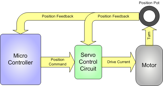
    Analog feedback servo motor feeding the potentiometer information from the motor shaft to the microcontroller


    The Microcontroller

    After starting off with an Arduino UnoI decided to use an Arduino Mega 2560 because it has loads of analog inputs should I want to add more sensors in the future. 

    The analogue feedback sensors are controlled by PWM pins D2-D6 on the Arduino Mega 2560, and the feedback values read by analogue inputs A2 – A6:

    This design was transferred from breadboard onto an Arduino Mega shield:


     The servos are powered by a 6 Volt power supply, whilst the Arduino is powered and connected to a computer via USB. The camera responsible for collecting visual data is directly connected to the computer via USB as well. 

  • Designing and Building a Hand Prototype Part 1

    Stephanie Stoll08/27/2017 at 11:47 0 comments

    This log describes the design of the hand chassis, and the mechanical transmission system. The electronic circuitry and sensor modalities will be discussed in a later entry. 

    Design Considerations

    I chose to go with a five finger anthropomorphic hand design as opposed to some sort of two or three finger gripper for the following reasons:

    • to enable the hand to grasp a range of different objects. The human hand has specialised itself over time to become the perfect multi-purpose tool, allowing for a wide range of different grasps, such as pinch, wrap, circular grasp. See the below chart for details [1]. 
    • to address my original motivation of researching prosthetics, a human hand design makes the most sense.
    • to utilise open source materials available on anthropomorphic hand designs. Although I designed my prototype from scratch, there is a vast pool of inspiration to be taken from fantastic projects such as Gael Langevin's InMoov hand [2]  or OpenBionics [3].

    The Hand Chassis and Tendon-Based Transmission System

    All parts for the hand were designed in Autodesk Fusion 360 (freely available for students!) and printed in PLA plastic.  

    All fingers consist of the same base parts (see below), only the base of the male and female part changes size according to the length of the specific phalanx.

    Finger parts 
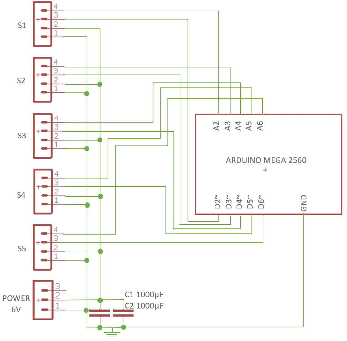
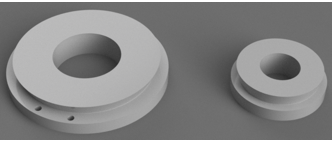
finger tip (left), male phalanx base part (middle) and female phalanx base part (right).

     Phalanges are connected with joints rotating around 2mm metal rod. The finger assembly was tested on a printed finger base:


    Next, a palm was designed with five male finger parts as the base for each finger and the thumb. The initial palm design was supposed to house the camera before it was moved to the wrist, hence there are guides for the Bowden system and space for the camera inside the palm. 

    I went on the print and assemble the first hand prototype:


    Once the first hand was printed it needed to be actuated using five servo motors. The five servos are housed in a servo bed with guides which lead the tendons from the palm to the servos. The tendons are mounted onto each servo horn using two servo rings of different sizes, as I found this gives the maximum turn with minimum backlash.  This is due to the way the fingers bend the opposing tendons don’t expand and contract by the same amount. The palm design needed to be altered at the wrist to allow for two M3 bolts to connect the palm to the servo bed. Here are some renderings of the altered palm design(a) and the servo bed (b), as well as their assembly.


    These are the servo rings used to connect each tendon to its servo:


    To complete the actuation and transmission part of the hand, two tendons were run through each finger, for extension and contraction respectively. The tendons run out of each finger into a Bowden system, through the palm and out through the wrist into the servo bed to their respective servo motors. 

    The tendons itself are 0.5mm closed loop wire which is normally used for transmission in model aircrafts. The wire was crimped to the servo rings using 0.5mm diameter aluminium ferrules. 

    The Bowden system was built using 1mm inner diameter/2mm outer diameter PTFE tubing.

    To be able to use the hand prototype in different positions I designed a cover for the servo bed that allows for the hand to be placed on its side, facing up, or facing down. This provides flexibility for using the hand in different settings and makes the actuation system less prone to damage. Please note that in order for the thumb to move freely you need to saw off the right corner of the cover (I haven't gotten round to changing the STL file, sorry).


    After testing the assembled hand, it became apparent that embedding the camera into the palm was impractical, and it was moved onto the servo bed cover instead. For this a mounting bracket (b) was designed and the palm covered with a lid (a):

    The overall design was refined by adding a soft silicone coating to each fingertip (toe...

    Read more »

View all 11 project logs

  • 1
    Building and Maintaining the Transmission System

    Given that I snapped two tendons whilst testing the hand the other day, I thought this was a good opportunity to provide some detail on the hand's actuation and transmission system and show how to wire up a finger. 

    Just to recap, the hand is actuated using five servo motors. The five servos are housed in a servo bed with guides which lead the tendons from the palm to the servos. The tendons are mounted onto each servo horn using two servo rings of different sizes, as it was found this gives the maximum turn with minimum backlash. 

    From each servo, two tendons run  into a Bowden system and through each finger, for extension and contraction respectively.

    The tendons itself are 0.5mm closed loop wire which is normally used for transmission in model aircrafts. The wire was crimped to the servo rings using 0.5mm diameter aluminium ferrules. 

    The Bowden system was built using 1mm inner diameter/2mm outer diameter PTFE tubing, originally destined to be used as a Bowden system for the RepRap 3D printer. 

    Actuation and Transmission System
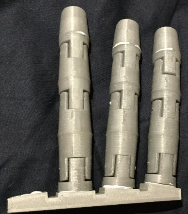
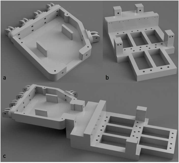
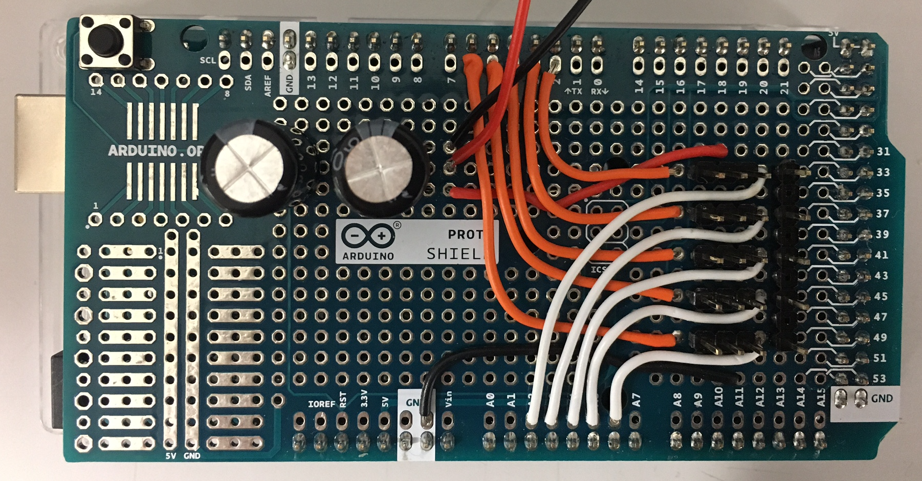
This shows the full positioning of the servos, as well as the whole Bowden system (ignore the cables, they were for some force sensors I tried).
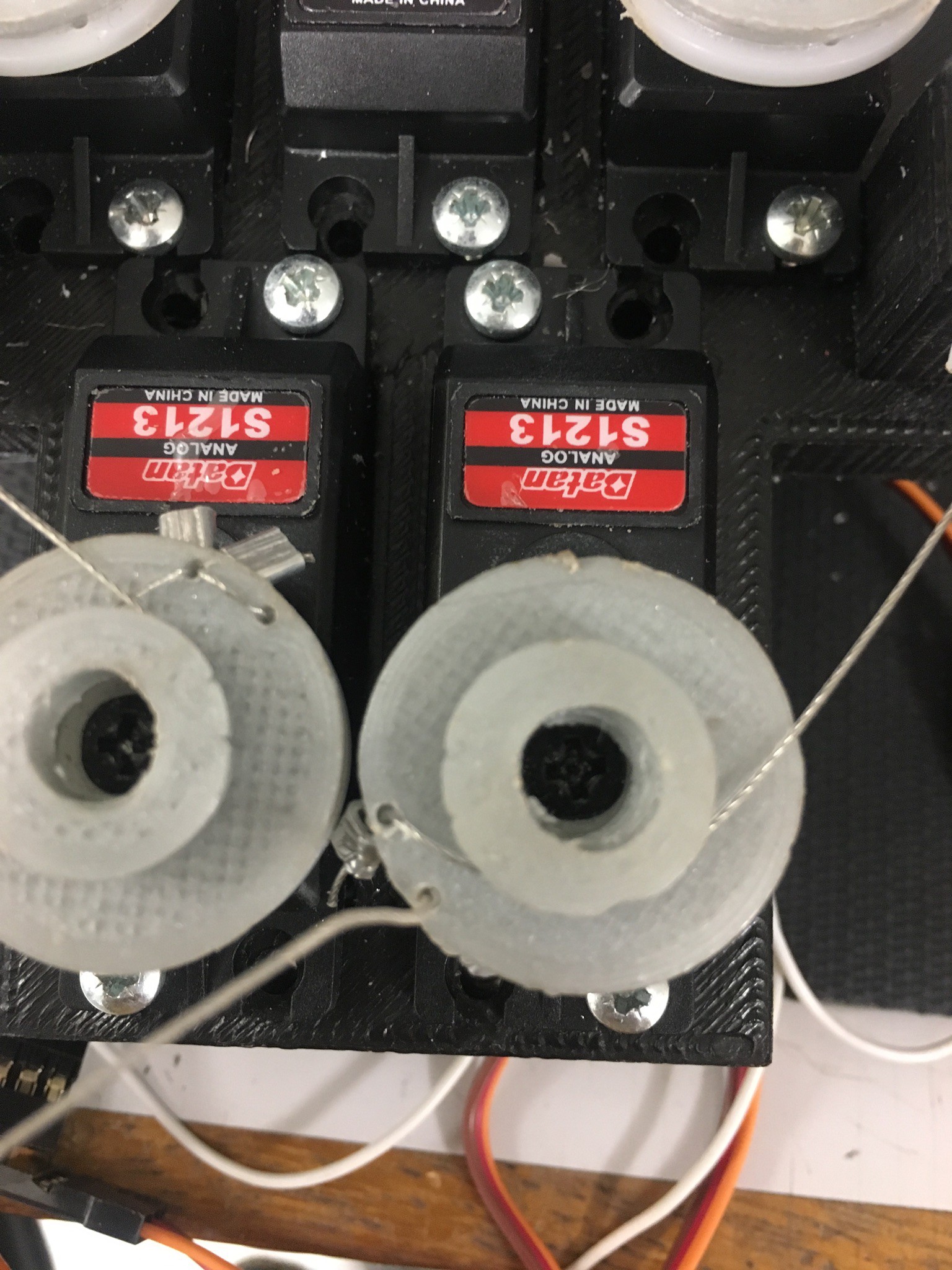
  • 2
    Wiring up the front tendon

    The front tendon runs along the lower, bigger circle of the servo. Apart from that it's pretty much the same as the back tendon.

  • 3
    The Problem

    The tendons in the transmission system are subject to wear and tear and tend to snap at some point (believe it or not, one of the tendons in the middle finger broke 5 minutes before my Viva, giving my examiners the finger).

    Today we are going to fix two snapped tendons: the extension tendon of the middle finger (the back one that pulls the finger back) and the little finger front tendon that makes the finger bend.

View all 4 instructions

Enjoy this project?

Share

Discussions

Similar Projects

Does this project spark your interest?

Become a member to follow this project and never miss any updates