Close
0%
0%

RAPTA - Autonomous Humanoid Leg

Dynamic, adaptive control systems for real-world robots

Similar projects worth following
The RAPTA project is a purposeful, autonomous robotic system that demonstrates a unique approach to overcoming the problems of artificial systems required to operate in dynamic, unpredictable environments. In other words, the real world! The principles behind the approach apply not only to robotic legs, but to any form of robotic system. Up until now, robots have largely been a failure in real world environments, but as the desire and demand for dynamic robotics systems is very high the potential for the approach followed by this project is significant. The social benefits for such robotic systems are compelling, particularly in the areas of assistive technologies, hazardous environments and space exploration. RAPTA = Robotic Autonomous Perceptual Tracking Agents.

2017HackadayPrize Final Video

Introduction

The rationale behind this project is based upon a radical theory of how all living systems, including humans, operate in dynamic, unpredictable environments. Instead of responding to stimuli we purposefully control and maintain the way we perceive the world at desired values. For example, when talking face to face with someone we control our perception of the space between us at a level that is comfortable to us, and move back or forward accordingly. The difference between this and the stimulus-response approach may seem subtle at first, but actually is fundamental in terms of the resulting architecture.

The stimulus-response approach actually requires a great deal of complexity and precision within the mapping between the stimulus and the response, as it needs to model the correct response for every instance of the stimulus. It would also need to deal with environmental disturbances which are generally unpredictable and unknown. This is not the case with the perceptual control approach as it is the perceptual input that is controlled not the action response. To put it another way it is not action that is controlled but the consequences of action. The perceptual control approach works by varying the action output to maintain the desired perception. 

In this way it does not need a mapping between input and output (stimulus and response) and also is able to compensate for unpredictable environmental effects. In contrast to conventional approaches to behaviour and robotics, purpose (goals) is inherently embodied within the architecture of the closed-loop control system as the perceptual variable that is under control.

To give another example, when driving we control our perception of the car between the white lines (the goal). We don’t turn the wheel to a specific angle or by a specific amount, but until the perception is as desired. Many factors can affect the heading of the car; wheel balance, tyre pressures, rain, road surface and especially wind. But we don’t need to know anything about them as we simply counteract their combined effects on the perceived position of the car.

In principle, this approach, of a hierarchy of simple feedback control systems, can explain behaviour at all levels of complexity.

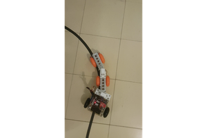
RAPTA is a system that embodies this goal-directed methodology, by way of a software platform for designing and implementing the hierarchical control system architecture on robotic hardware systems.

I am an independent researcher and am the sole designer and implementer of the software platform and hardware configuration associated with this project.

Robotics

The foundation, of a hierarchy of control systems, represents an ideal and relatively simple architecture to apply to general robotics, which I have described further in my recent paper in the Artificial Life journal, "A General Architecture for Robotics Systems: A Perception-Based Approach to Artificial Life.

Essentially, the architecture makes it possible to build up a hierarchy of perceptual control systems for increasingly complex behaviour. At the lowest level is the interface with the environment, comprising sensory inputs and actuator outputs. At each subsequent level the perception being controlled may be a more complex perception such as a combination of lower level perceptions or a derivative of a lower level perception.

So, this architecture enables a complex, goal-oriented robotic system to be constructed in a modular fashion just from the basic building block of a perceptual control feedback system. This avoids the complexities and inflexibilities of the conventional approaches of kinematics and intricate mathematical models of the physics of the world and the dynamics of motion.

The application of this methodology to artificial systems has significant implications for the world of robotics. It indicates that complex systems can be developed from simple principles that everyone can understand. These systems...

Read more »

Leg System.lxf

Lego Digital Designer file for the full leg system.

lxf - 22.02 kB - 09/28/2017 at 09:54

Download

Leg System.xlsx

Components for the full leg system.

sheet - 130.43 kB - 09/28/2017 at 09:54

Download

011-006-LegControlProximityAccel.odg

Design and configuration of hierarchical perceptual control system for stand up and balance, control of proximity and variation of balance reference with a step function.

OpenDocument Graphics - 28.05 kB - 09/25/2017 at 13:00

Download

011-005-LegControlSequence.odg

Design and configuration of hierarchical perceptual control system for stand up and balance.

OpenDocument Graphics - 28.04 kB - 09/25/2017 at 13:00

Download

011-003-LegControlMotors.odg

Design and configuration of hierarchical perceptual control system for balance using two motorised joints.

OpenDocument Graphics - 21.30 kB - 09/25/2017 at 13:00

Download

View all 8 files

  • Closeup of gear system

    Rupert Young10/09/2017 at 13:42 0 comments

    Here is shown closeup footage of the gear system in operation as the leg moves according to a step change function of the high-level balance reference goal.

  • Stand up, balance and proximity control - video

    Rupert Young09/28/2017 at 12:47 0 comments

    For the purposes of this project the system demonstrated in this video represents the final version. As with previous versions it controls the elevation of the leg, so that it stands up, while controlling the balance sensor horizontally. It then continues to control the balance in the face of disturbances.

    Additionally, it also controls proximity to an object. It does this by dynamically changing the goal of the, lower, balance control system. 

  • Stand up, balance and proximity control - design

    Rupert Young09/28/2017 at 10:59 0 comments

    The design shown below builds upon the previous version by adding an additional control system that controls the proximity, related to the ultrasonic sensor. The proximity control is achieved by changing the goal of the, lower, balance control system. The balance system itself controls its own perception by changing the power applied to the motors. 

    The resulting behaviour of the proximity control is that the top section of the leg re-balances in order to maintain the distance between the ultrasonic sensor and the object at a target value (~15cm). 

    This system encompasses the same functionality as all previous stages, but extends the functionality with the additional control system. This demonstrates a fundamental principle of the methodology, that the architecture is infinitely scalable; by adding the the modular perceptual control systems.

  • Stand up and balance - video

    Rupert Young09/27/2017 at 14:08 0 comments

    The system demonstrated in this video initially controls the elevation of the leg, so that it stands up, while controlling the balance sensor horizontally. Then it continues to control the balance in the face of disturbances.

    The video shows repeated demonstrations of this sequence with different values being set for the angle reference. The result is the whole system moves up and down, while the balance is maintained at horizontal.

  • Stand up and balance - design

    Rupert Young09/25/2017 at 15:43 0 comments

    The design below shows the hierarchy for the leg system that raises itself to an elevated level while controlling the balance. The system than continues to control balance.

    This is achieved by controlling a sequence perception of two events; standing up and then continuing to balance. Firstly, the angle (tachomoter reading) of joint B is controlled by bringing it to a point where the system moves upwards from its initial position. As a smoother means to this end the joint speed and acceleration are also controlled.

    Secondly, control switches to continuing balance once the angle control system reaches its goal. At this point the angle system becomes inactive.

  • Balance with two motors - video

    Rupert Young09/25/2017 at 15:14 0 comments

    The system demonstrated in this video is the next step on from the previous system as two motors are used in the balancing of the system rather than just one.

    Two control systems control a perception of balance by varying the power to different motors. The independent action of the two motors have complementary effects on the balance system so that the goal is reached.

  • Balance with two motors - design

    Rupert Young09/25/2017 at 14:49 0 comments

    The image below is the design layout of the leg system that balances on the basis of two motorised joints. This corresponds to the ODG file 011-003-LegControlMotors.odg added to the project files. 

    There are two control systems both of which control the acceleromter X value at a goal reference value. The output from each affects a different motor, to a degree that is a function of the balance error. 

  • Balance with one motor - video

    Rupert Young09/25/2017 at 13:46 0 comments

    The video here shows the operation of the balance system by way of a single motor. The motor power varies in order to maintain the accelerometer balance sensor value at its reference value.

  • Balance with one motor - design

    Rupert Young09/25/2017 at 13:28 0 comments

    Here be the first design of the leg system on the progression towards the full system. This corresponds to the ODG file 011-002-LegControlMotorC.odg added to the project files. 

    There is a single control system which controls the acceleromter X value at a reference value by setting a motor power proportional (sigmoid) to the balance error. The X value of the accelerometer is zero when it is level.

  • Software platform example

    Rupert Young09/25/2017 at 11:35 0 comments

    The video below shows basic usage of the PCT Monitor graphical user interface for visualisation of the data involved with a live environment. The particular control system design is shown in this image. The configuration controls a perceptual sequence, of the system standing up while controlling balance and then maintaining balance in the face of disturbances. 


    The video demonstrates and describes some of the features of the monitor. 

    • the GUI connects over the network to a running live robot system,
    • each of the control systems in the configuration can be viewed as a set of live signal values,
    • graphs can be created to plot any of the signals,
    • parameters on the live system can be modified via the GUI during execution.

View all 12 project logs

  • 1
    Build perpendicular gearage

    The images here show the design of the perpendicular gearage system, prepared in Lego Digital Designer.  

    The list of components (BOM) are in the file Perpendicular gearage.xlsx

    The building instructions can be found in the Lego Digital Designer Perpendicular gearage.lxf and online here.

  • 2
    Build humanoid leg

    The image here show the design of the full leg system, prepared in Lego Digital Designer.  

    The list of components (BOM) are in the file Leg System.xlsx.

    The building instructions can be found in the Lego Digital Designer Leg System.lxf and online here.

    A Mindsensors AbsoluteIMU sensor is attached below the two yellow stoppers just behind the ultrasonic sensor with the X axis pointing in the direction of the sensor, as shown in the camera picture in a subsequent build post.

    The port connections for the sensors and motors are as follows:

    EV3 Ultrasonic sensor - S3

    AbsoluteIMU - S4

    Lower NXT Motor - B

    Upper NXT Motor - C

  • 3
    Perpendicular gearage

    For some reason these instructions won't allow two images, so here is the underside of the perpendicular gearage.


View all 4 instructions

Enjoy this project?

Share

Discussions

Similar Projects

Does this project spark your interest?

Become a member to follow this project and never miss any updates