 SimpleTronic
Quick Tour Video:
Circuit Diagram:
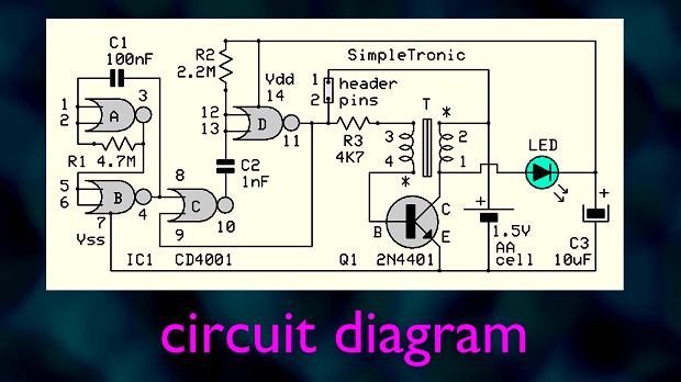
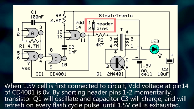
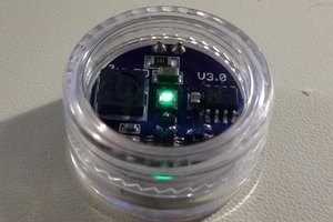
Circuit is basically a "gated" blocking oscillator (joule thief) . IC1 CD4001 requires 3V and will not run from 1.5V (AA cell) when first connected. By shorting the header pins 1-2 momentarily, circuit oscillates and flyback voltage pulses appear at collector of transistor Q1. These pulses are rectified by LED and charge capacitor C3 while at the same time light is emitted by LED. Now, CD4001 is powered from C3 with adequate supply voltage, and produces short pulses (1.5mS) at a rate of 1Hz (header pins disconnected). Cycle repeats until 1.5v cell is depleted.

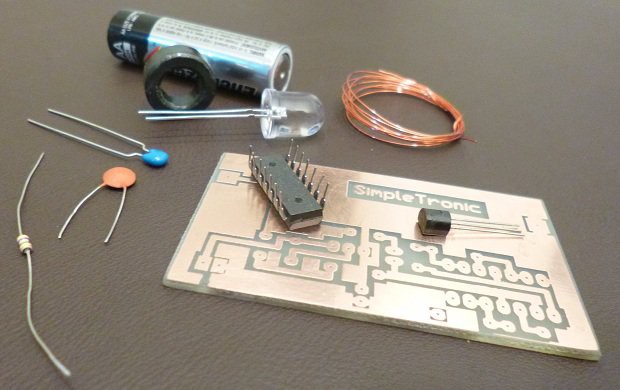
Component List:
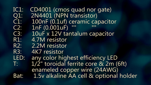
Led should be of maximum efficiency (current is very small).
Download Link to PCB & component placement guide:

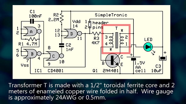
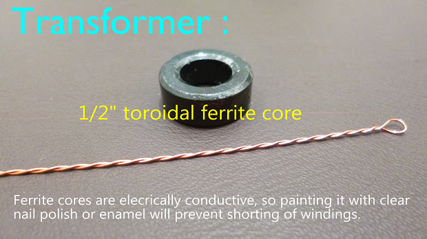
Transformer Build:


 Ted Yapo

 Christoph Tack
 mattko
I reckon if you used a CR123A lithium battery, you would gain in several ways in return for the extra cost. They are about $2 each in quantity.
Much longer operational life, perhaps even 20+ years. I had a CR123 in a film camera that I stopped using in 2006. When I turned on the camera in 2019 it was still viable. I doubt if an alkaline cell would last 10 years, I have several leak after a few years.
Much simplified circuit, no need for coil since the CR123A is a 3V cell.