 Peter Walsh
This is a completed project, expect no more updates or changes.
I'm still working on improving the Haber process using a different method, and I have made some progress. I'll start and update a new project describing my work at some point.
Summary
A home-built ultrasonic system that can be used for:
- Ultrasonic mixing
- Drilling
- Plastic welding
- Ultrasonic levitation
- Sonochemistry
- Installing metal inserts (in plastic)
- Experimentation and exploration of cavitation
And to change the world:
- See if ultrasonic cavitation can fixate Nitrogen less expensively than the Haber-Bosch process
All project information will be open source: schematics, plans, build instructions et. al. will be available on GitHub under the MIT license for the hobbyist to construct their own ultrasonic system.
Additionally, experimental procedures exploring the Haber process will be described in enough detail to allow other researchers to recreate the experiments.
Current Status
I have a working home-built ultrasonic system and demo videos for several of the design goals.
The existing system does levitation, mixing, cavitation, and sonochemistry. Demo videos are in the links section, which should be in the left column of this page.
The system can be built by hobbyists, the power level is adequate for the purpose, it's reasonably safe for casual use, and not difficult to set up and operate. It will power transducers up to 120 watts.
The system will melt plastic, but as yet I haven't been able to get the melt to appear between two sandwiched pieces (welding), or to surround a metal insert. Welding and installing inserts still appear to be achievable goals.
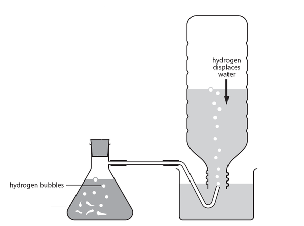
For Nitrogen experiments, I have a Hydrogen generator, a Nitrogen generator, a gas collection system, a mass flow controller, and a reaction vessel. (And a working ultrasonic system that produces cavitation.)
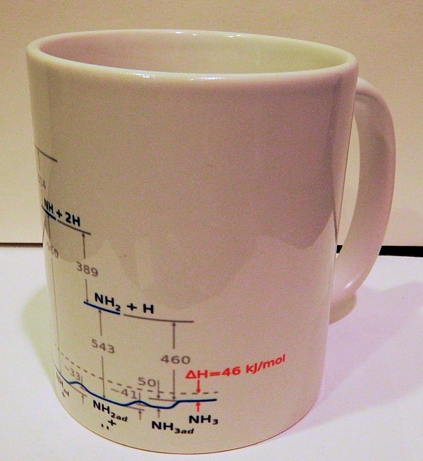
Making Ammonia from Nitrogen
The project description gives a good overview of the problem to be solved.
Fixing atmospheric Nitrogen into ammonia (or any other nitrogen-based compound) would reduce the cost of fertilizer worldwide, allowing us to feed more people at less cost, and globally reduce the amount of energy used.
Per calculations in my previous build log, the Haber process produces 17 grams of ammonia using over half a million joules of energy. For comparison, that much energy will run a 100 watt incandescent bulb for over 90 minutes.
That's the number to beat: generate 17 grams in 90 minutes, using 100 watts or less.
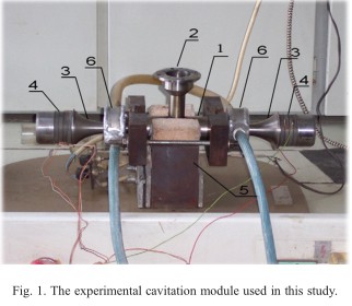
Ultrasonic fixation of Nitrogen has been tried before, but my methods are different:
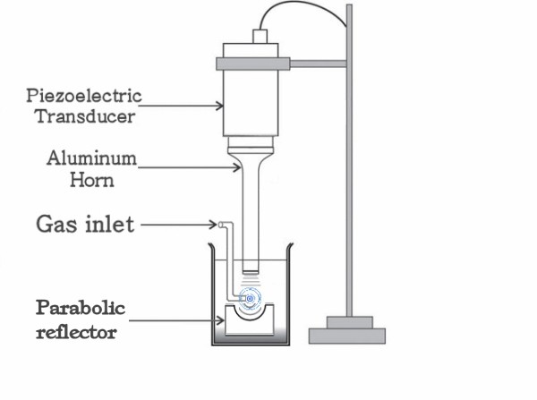
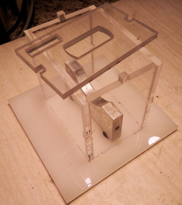
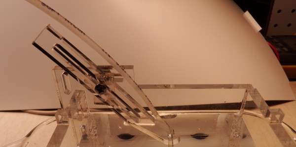
- I'm using a parabolic reflector to focus the ultrasonic energy to a high level, and
- I'm directly sonicating a bubble instead of relying on dissolved gases
No previous experiments (as far as I can tell) have used this type of setup, so this is unexplored territory.
I'll be experimenting with Nitrogen fixation for the next few years. This is science, there's no guarantee this will work, and it may not work before the end of the contest.
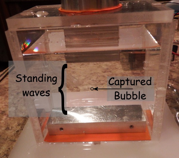
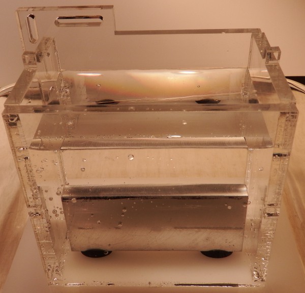
The video below shows cavitation in the reaction chamber.
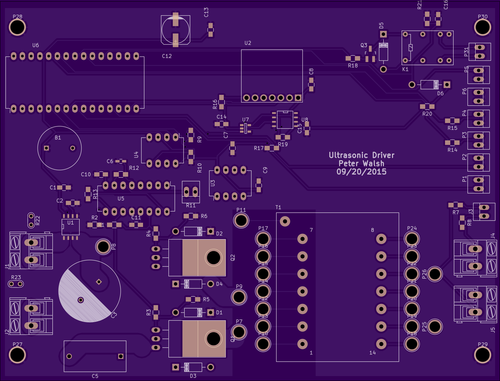
System Design
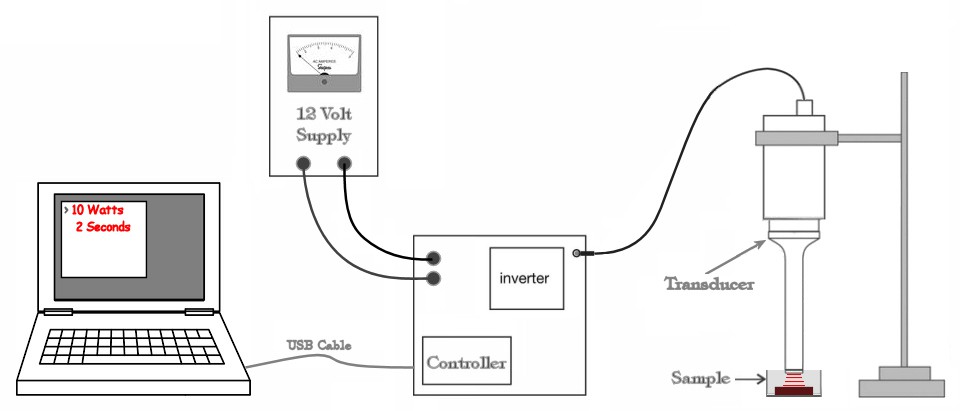
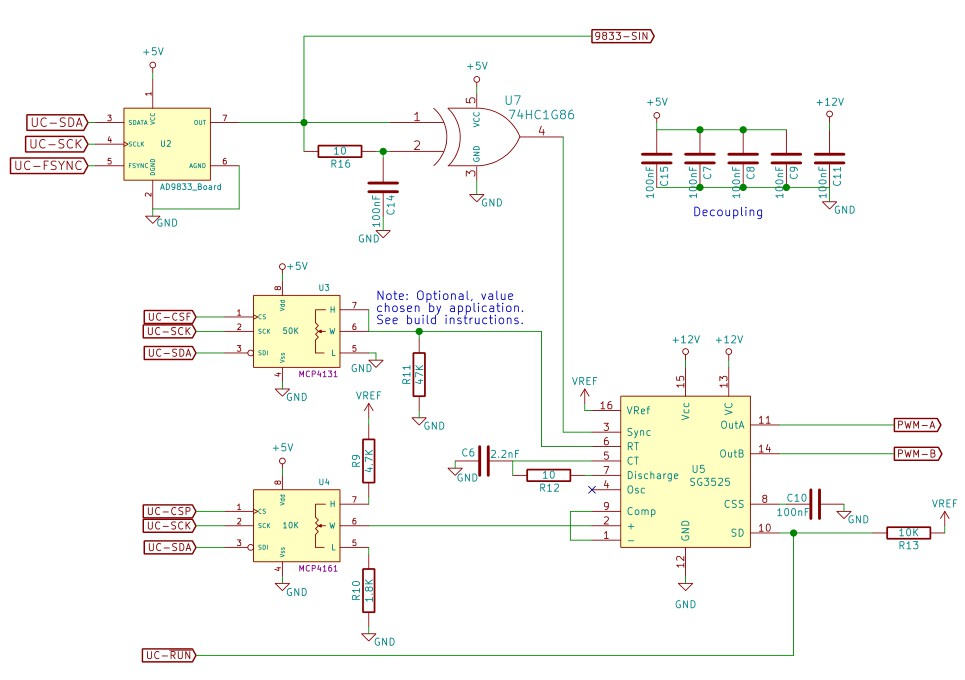
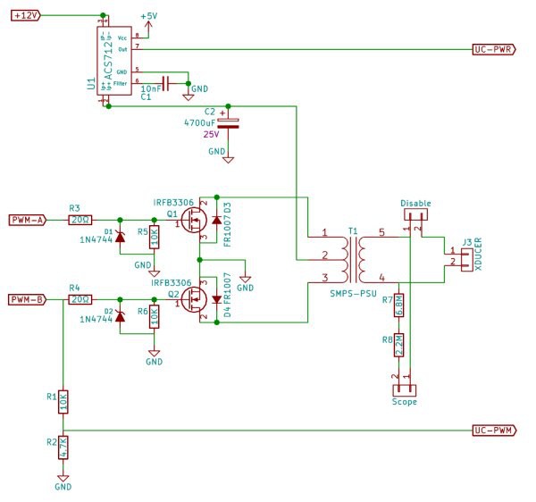
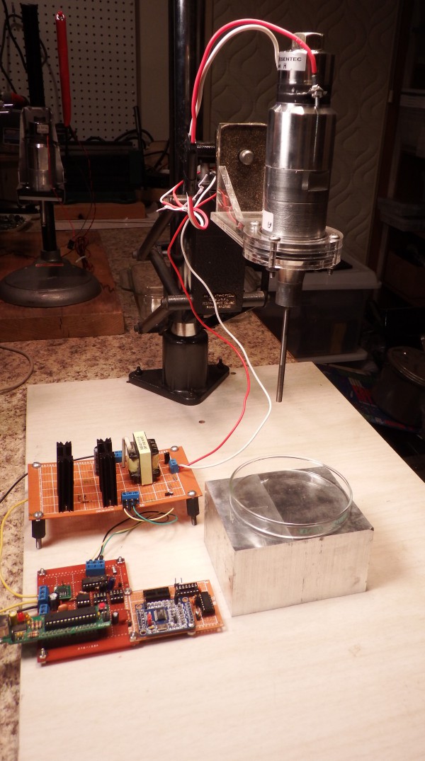
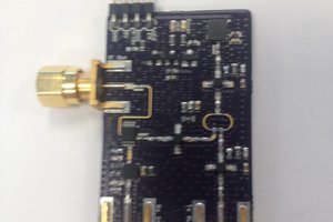
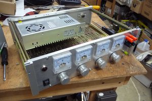
The system is a high voltage power supply driving an ultrasonic transducer from eBay.
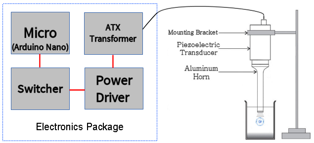
An Arduino Nano sets the frequency and pulse width of a UC3525 PWM chip, whose output controls a half-bridge power driver that switches 12 volts across the 5 Volt winding of a scavenged ATX power transformer. The output (around 300 volts) drives the transducer.
The actual power delivered to the sample depends on how close the frequency is to the resonant frequency of the transducer. For off-resonance impedance of 1000 ohms, the delivered power is 84 watts at full modulation. At resonance (25 ohms), the supply will reduce the PWM to limit the output to the rated capacity of the transducer, to a maximum 120 watts.
The switcher and driver/ATX output circuits:
MIT License
This project is released under the MIT license (details here), which means you can do anything you like with...
Read more »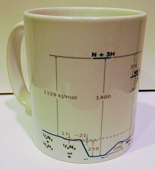


 Rue Mohr
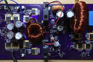
did the tech not work?