Close
0%
0%

5V 25W Synchronous Buck for 12V Systems

5 Volt, 25 Watt synchronous buck using the PIC16F1769 micro-controller.

Similar projects worth following
5 Volt, 25 Watt synchronous buck using the PIC16F1769 micro-controller. Designed for charging USB devices with an off-grid solar panel system.

This is a derivative work and was conceived out of the need for a 5V USB mid-power charging station solution for my pilot solar panel installation.  While there's nothing special or impressive in its feature set, it serves up respectable performance using a PIC micro-controller rather than employing a monolithic solution.

I like using micro-controllers for many of my power supply designs because of the creativity & flexibility they allow.  And with the on-board peripherals you can implement some fairly complex features with minimal external components.

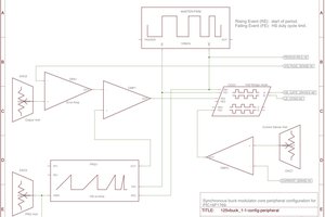
An example of this is the synchronous buck implementation.  I don't go into all the gory details in this project but instead posted as a separate project since it stands on its own as a concept that could be implemented on various designs & controllers.

The operation of this design is included in the description of operation PDF in the files section.  All files you need to build it are also there.  Details are included in the build section.

125vbuck-mplab.zip

Source code for controller.

Zip Archive - 12.78 kB - 02/18/2018 at 15:06

Download

125vbuck-eagle.zip

Schematic and board files in Eagle.

Zip Archive - 120.03 kB - 02/18/2018 at 15:06

Download

125vbuck-desc_of_operation.pdf

Description of operation.

Adobe Portable Document Format - 710.39 kB - 02/18/2018 at 15:06

Preview
Download

125vbuck-case.pdf

Dimensions for Polycase drills.

Adobe Portable Document Format - 120.97 kB - 02/18/2018 at 15:06

Preview
Download

125vbuck-bom.xlsx

Bill of materials in Excel.

sheet - 19.60 kB - 02/18/2018 at 15:06

Download

  • 1
    Board

    125vbuck-eagle.zip contains the Eagle board & schematic.  There are custom devices in the design but that shouldn't cause a problem you need to modify them.

    Ideally 2oz copper should be used for the design but my builds have used 1oz without problems.  Advanced Circuits manufactured the boards in the photos.

  • 2
    Inductors

    This design uses three custom wound inductors:  current sense transformer, output filter, and flyback drive for the output SSR.  The cores for all three are in the BOM file along with notes on wire gauge and number of turns.

    Be sure to wind / install with the correct polarity or the CT & flyback could develop high voltages that damage components.  A few pictures are included for guidance.

  • 3
    Bill Of Materials (BOM)

    125vbuck-bom.xlsx contains the detailed component listing along with vendors.  Most can be ordered from Digikey.  They don't carry Magnetics MPP cores.  The core used in this design is popular and can usually be purchased on eBay.  I also couldn't purchase the controller from Digi and instead ordered direct from Microchip.

View all 5 instructions

Enjoy this project?

Share

Discussions

Similar Projects

Does this project spark your interest?

Become a member to follow this project and never miss any updates