Jon Davies "Woody"
-
Testing the Nixies
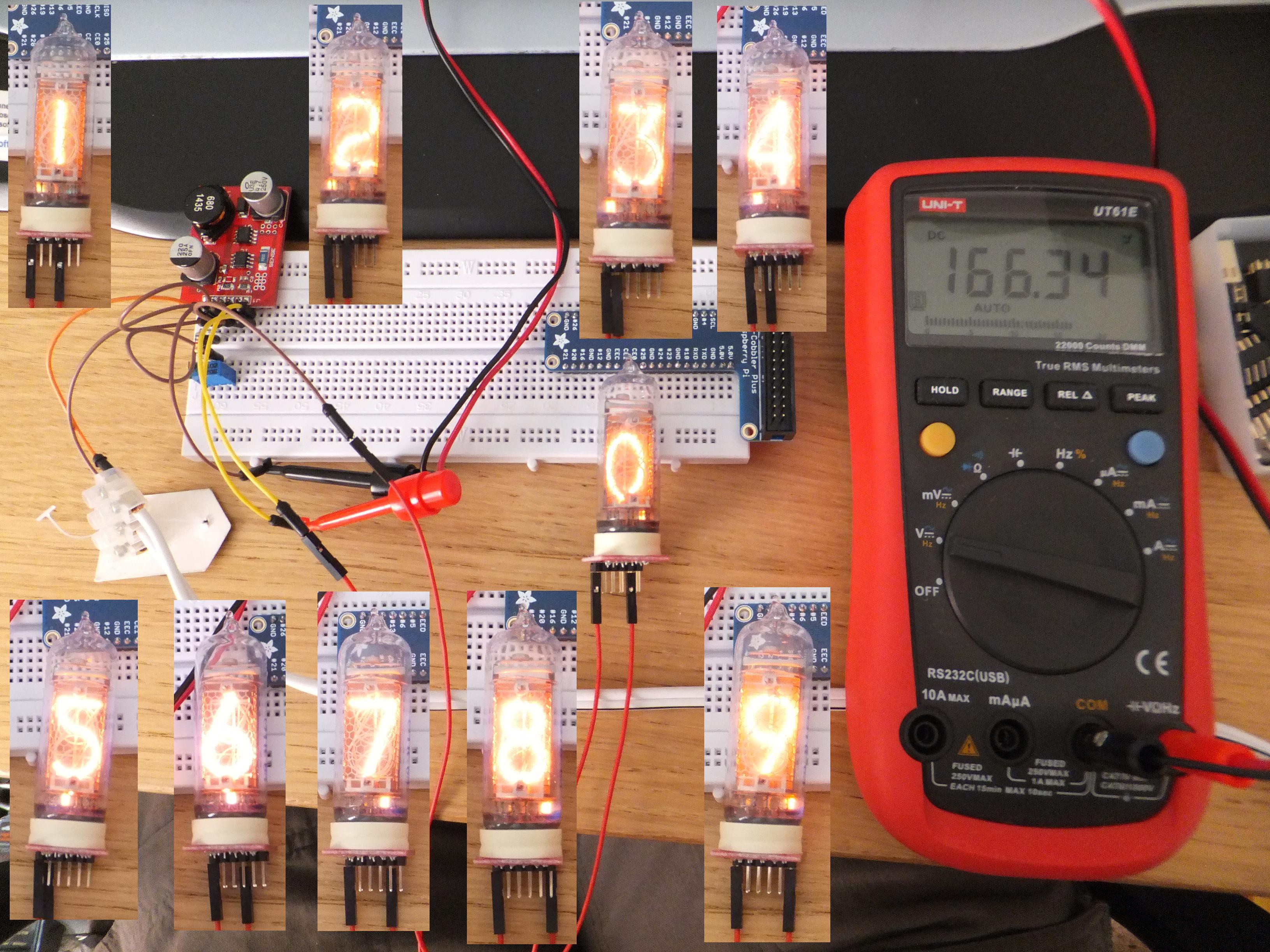
05/18/2015 at 02:57 • 0 commentsI wanted to check that all the numbers on all the tubes were working fine, so rigged up each digit on each of the six tubes in turn.
![]()
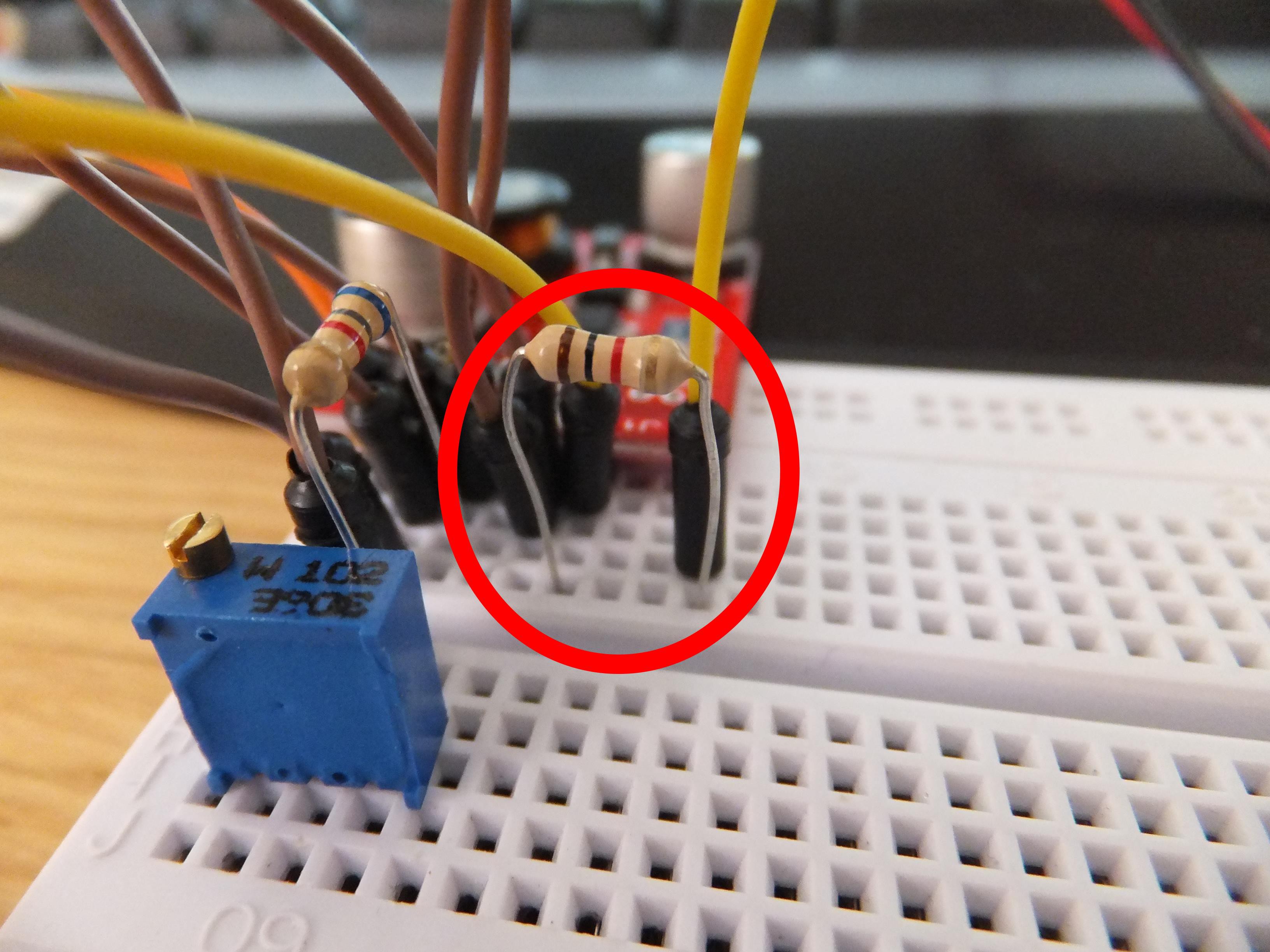
Thankfully, all the digits are operational - but that should be the case seeing as these are 'old new stock' aka old but never used. One thing that dawned on me during the first couple of Nixies, was I hadn't connected a current limiting resistor. D'oh! Hope I'd not shortened the lifetime too much, so reckoned on a 1k resistor based on an example circuit diagram that I'd been referencing. You'll notice a lack of this resistor in the above picture.
![]()
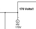
It also seems that 1k is minimal and 15k is more the norm when a Nixie is connected directly to a ~170 volt supply. Oops! :/ At least I was playing it safe as possible whilst running through all these tests...
-
Figuring out the Breakout Boards [pt2]
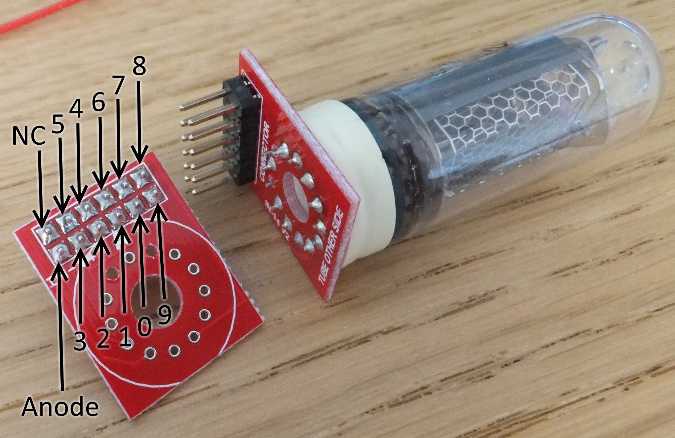
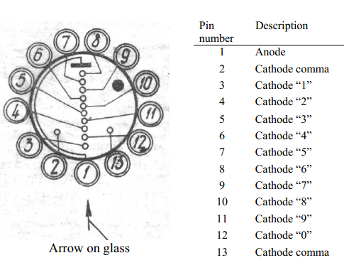
05/17/2015 at 16:08 • 0 commentsUsing a previous blog post 'Figuring out the IN-14 Nixie Tubes and Break-out Boards', I checked the pin numbers that relate to the display digits and probed the Tube-to-Pin Header connections with my Continuity Tester. From these tests, I noted the pinouts with the display digits for future reference.
![]()
-
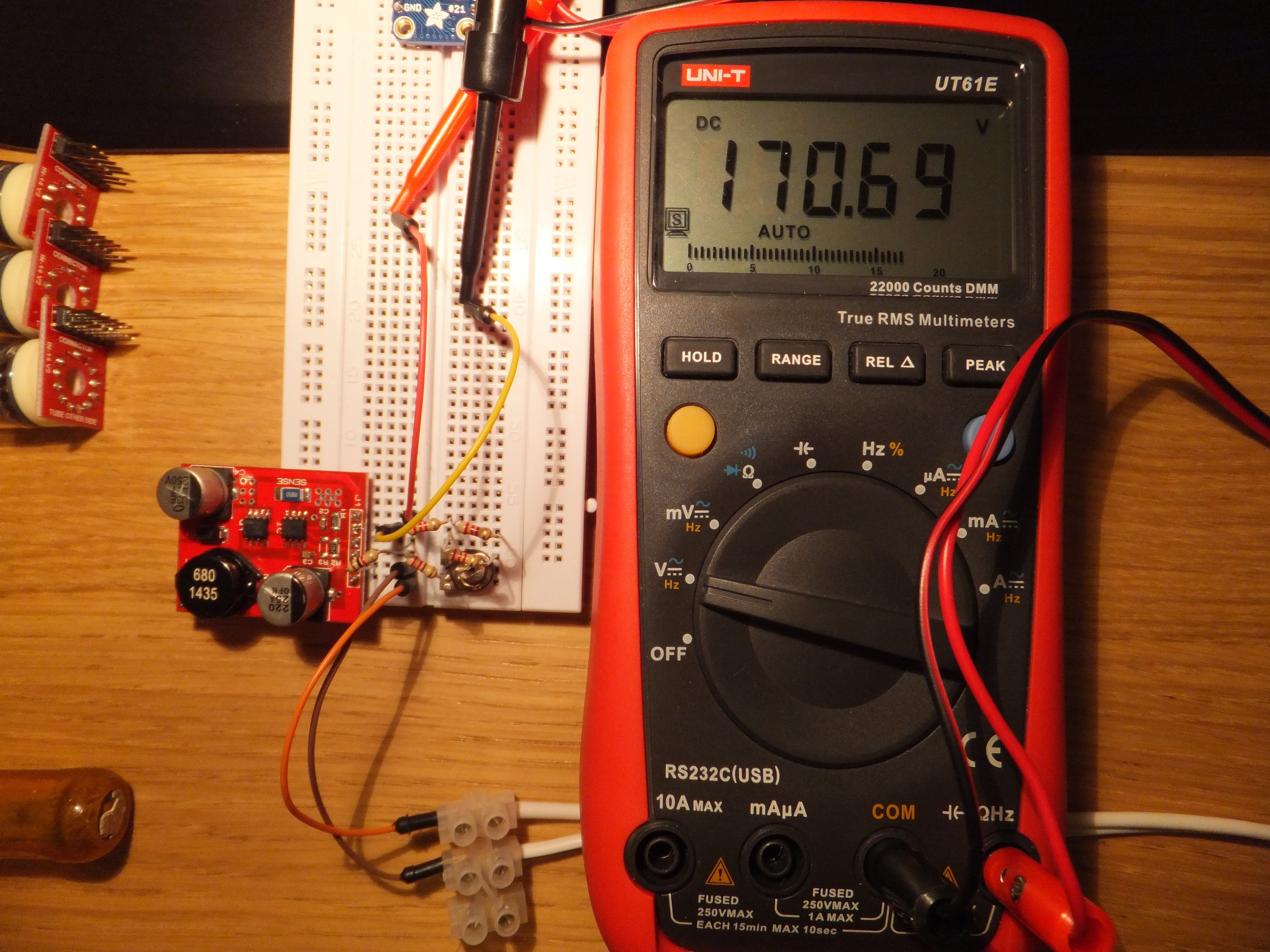
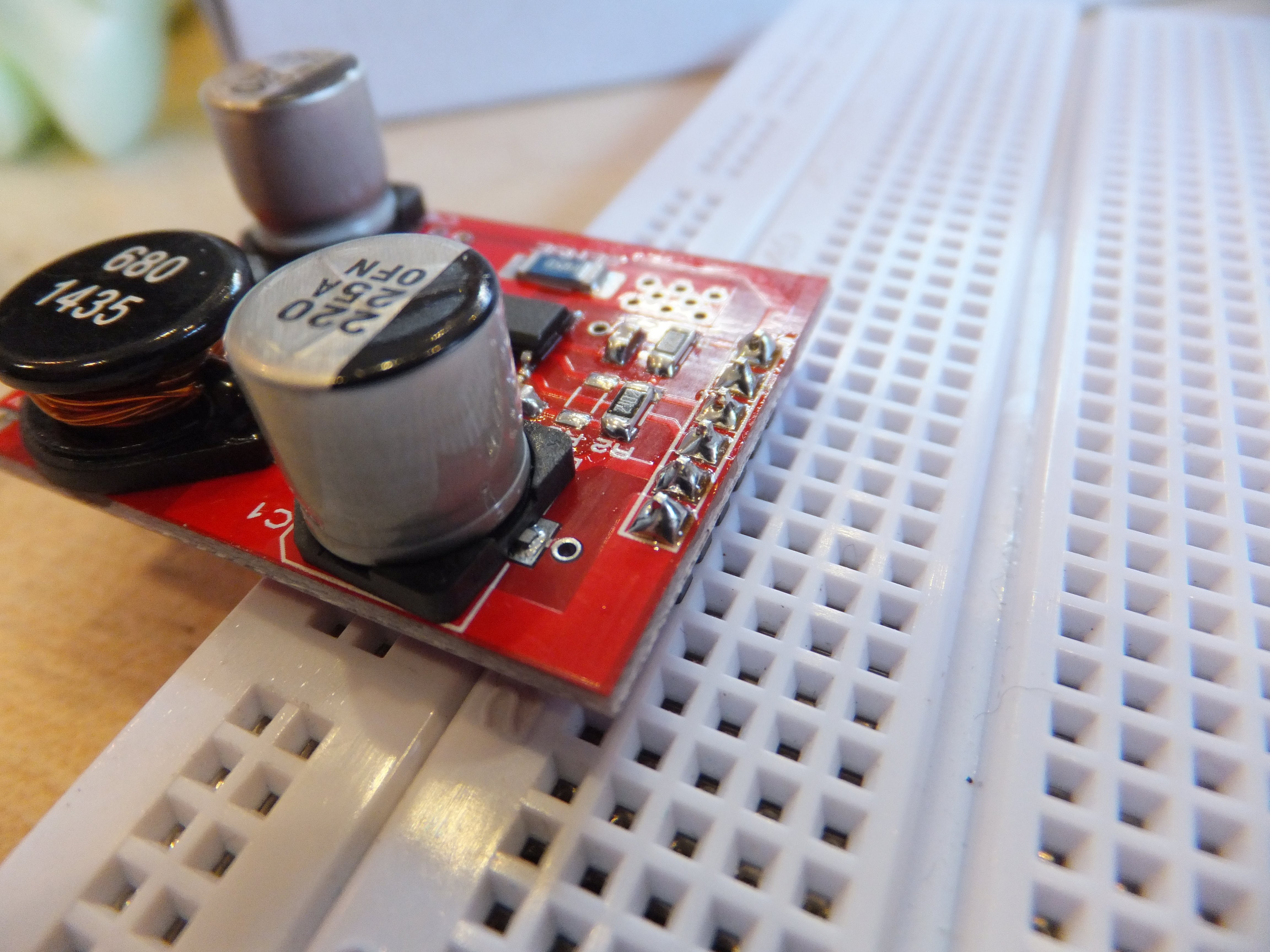
Testing the HV Module
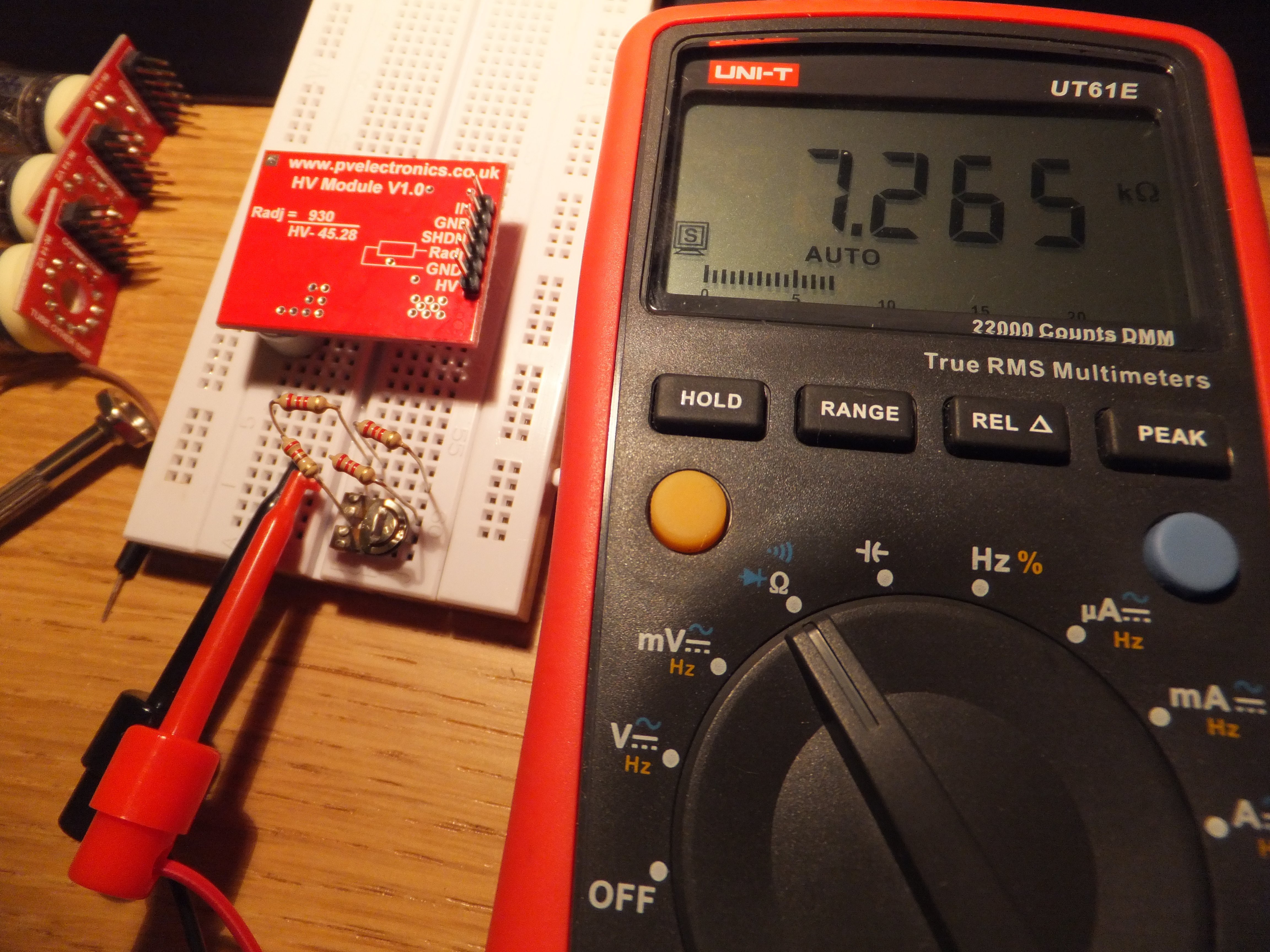
05/13/2015 at 01:12 • 0 commentsI couldn't put it off any longer, and had to test the HV [High Voltage] Module to ensure it worked, and that I could tune it for the right voltage. According to the various schematics I have checked, I needed a 6.8k resistor and a 1k potentiometer. I didn't have a 6.8k resistor, so made up the fixed resistance from 3x 2.2k and a 220 ohm. Fortunately, I did have a 1k potentiometer stashed in my old component drawers. I rigged up the resistors and did a quick test to check the resistance was in good order.
![]()
After that, it was time to connect 12 volts and power on. The first couple of attempts failed, and I thought the module was duff, but then I remembered the 'SHDN' pin. Seems obvious to most people that 'SHDN' is short for 'Shutdown', but I am the odd one out here and figured it out with good ole tinterwebs :) What I did reckon through previous experience, was that 'Shutdown' would be 'active high' according to the silkscreen label, so I tied the pin to ground [with a 1k resistor for the sake of it]. After this, bingo! And, got the trim measurement correct right off the bat.
![]()
Stand clear! Ne touchez pas! I thought it best to keep clear of my jump leads with bare ends and inappropriate test leads with exposed screws on the multimeter terminals! I waited a minute for the voltage to drop both on the multimeter screen, and the caps on the module to discharge. It might only give an unpleasant jolt, but I'd rather not confirm it!
So - that's another check complete - glad the module is working fine after all.
-
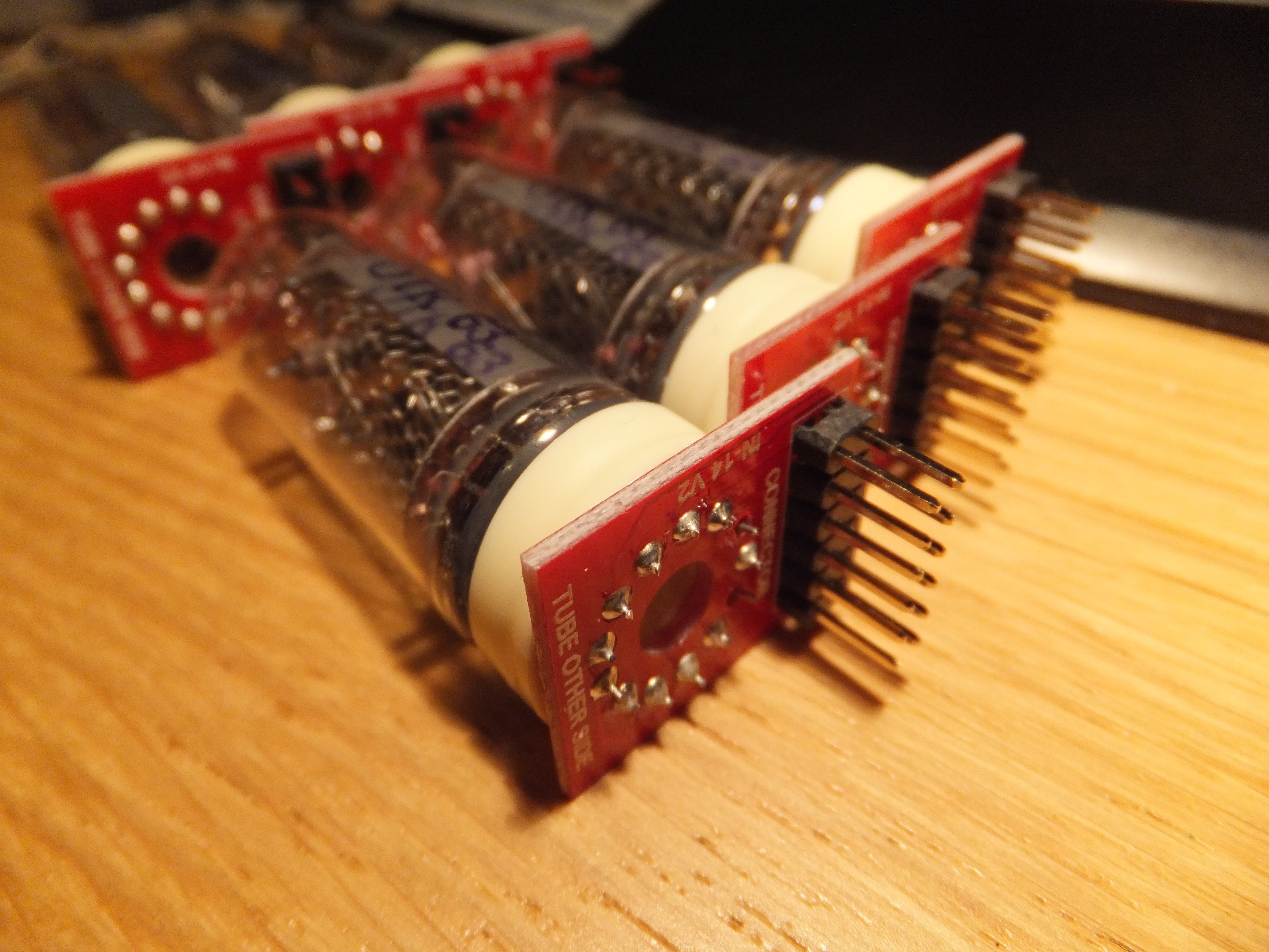
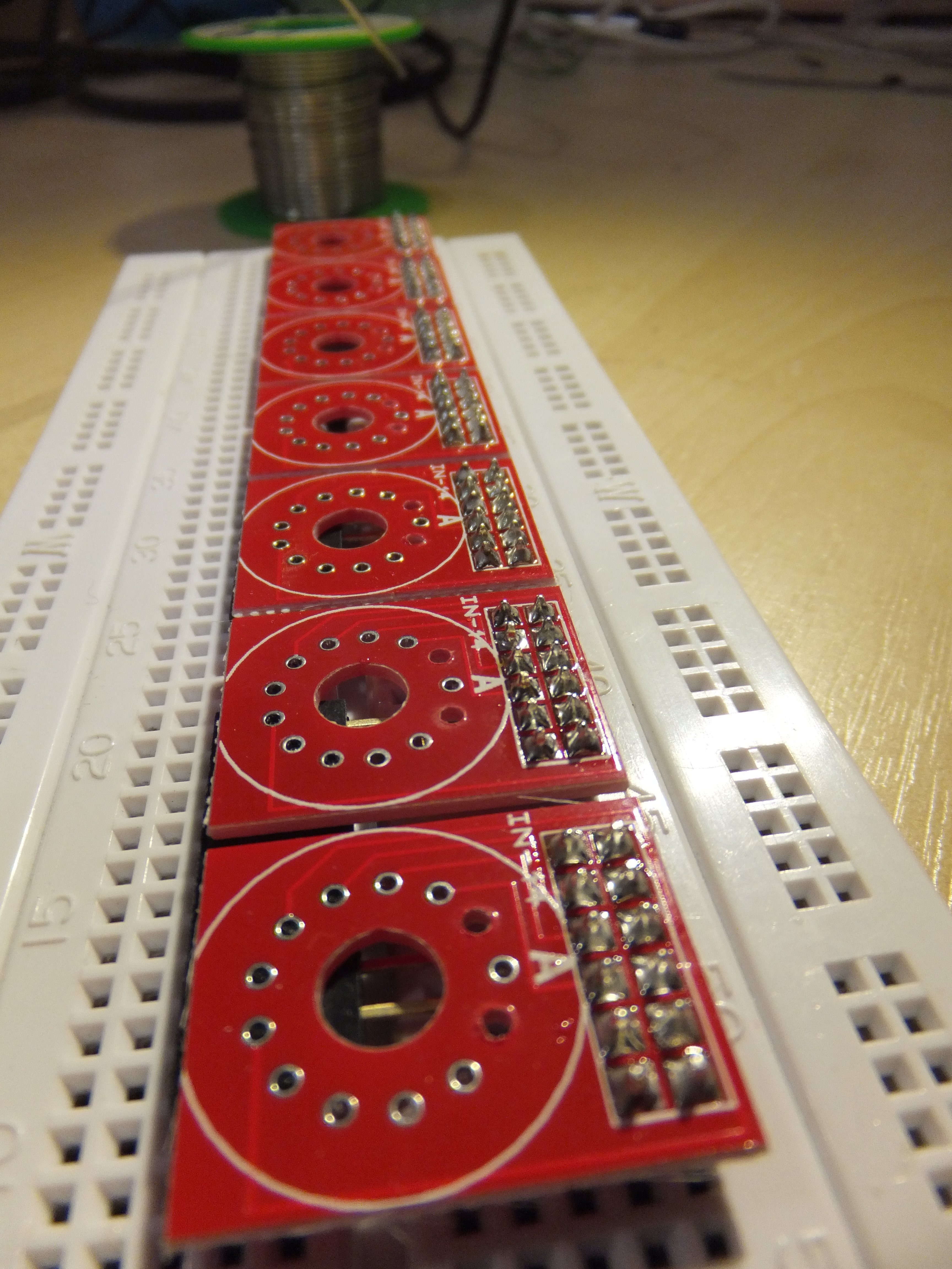
Soldering Nixies
05/13/2015 at 00:50 • 0 commentsTime to finish off the break-out boards by soldering in the IN-14 Nixie Tubes. I started off by threading all the connection leads through the break-out boards for all the Nixies before turning on the soldering iron. This was fidgety work, and if I had previously known that cutting each adjacent leg (in [say] the clockwise direction) a millimeter shorter than the one before it, the whole task would have been a lot easier.
![]()
Thankfully, my head was a little better screwed on when it came to ensuring the Nixies were soldered in properly and level. I started off by soldering just one leg, then checking there was no gap between tube and PCB at the solder point. If there was a gap, I'd re-melt the solder whilst pushing the tube down on the PCB.
![]()
I repeated the process for a leg on the opposite side of the tube, then proceeded to solder the rest of the legs. Wash, rinse & repeat another five times and presto! Finished Nixies & PCB mounts.
![]()
-
Directly interfacing the K155ID1 with Raspberry Pi?
05/13/2015 at 00:22 • 0 commentsAnother big question on my mind was if the K155ID1 Nixie Driver IC would be able to operate at the Raspberry Pi's relatively low 3.3 volts. I did a bit of hunting around the tinterwebs, and through all the speculation and suggestion of all manner of circuits, I came across a blog by a guy that took the plunge [Silviu G. Vulcan] and risked popping a Pi. The result? It works! Well...it did for him, and I suspect the success could vary a little from chip to chip.
![]()
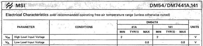
I even found, in a spec sheet, that the minimum logic 'on' state could be as low as 2 volts, but I did wonder if that also meant the Vcc for the chip could also go that low. Note that the K155ID1 is a clone of the SN74141, and the datasheet linked above is for the SN74141. The characteristics should be pretty well matched I hope.
![]()
-
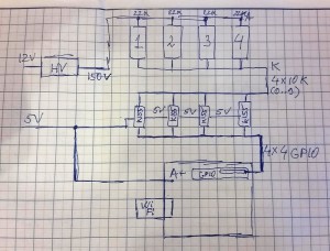
Figuring out the Nixie Circuit
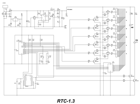
05/12/2015 at 19:28 • 0 commentsThis was in fact the first bit of research I did when setting out on this project, back even before I had bought the Nixie Tubes. At this point, I had been putting various items in the online shopping basket (including the Nixies) and had a suspicion that I'd need to control the Nixies from something that could interface logic 3.3/5v with the 170v required by the Nixies. This was the point at which I came across the K155ID1 Nixie Driver IC, and a suggested operating circuit:
![]()
I filled out the rest of my order based pretty much solely on this schematic, plus a few extras and minor modifications. I also got the HV Module as a result of simply asking an online agent where on earth the 170 volts was magically appearing from.
![]()
You don't ask, you don't get. Well, sort of - I still had to pay for the HV Module - free would have been nicer ;)
Looking at the diagram above, I can see that the K155ID connects to all the Nixie Cathodes on a bus, and each of the Anodes are switched by the PIC Micro-controller, meaning the K155ID is multiplexed. The benefits of this is that you only need one Nixie driver chip, and the circuit is less complicated. The disadvantages are [potentially] noise and flicker caused by the multiplexing.
I'm opting for multiplexing for now and will see how the results pan out.
-
Drilling and Soldering PCBs
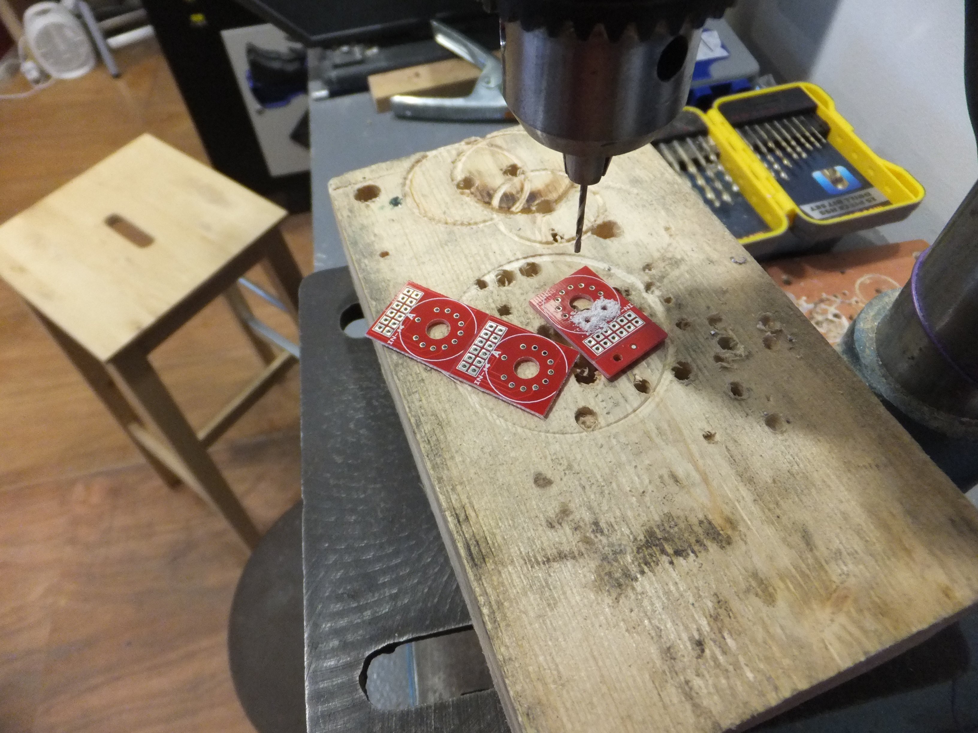
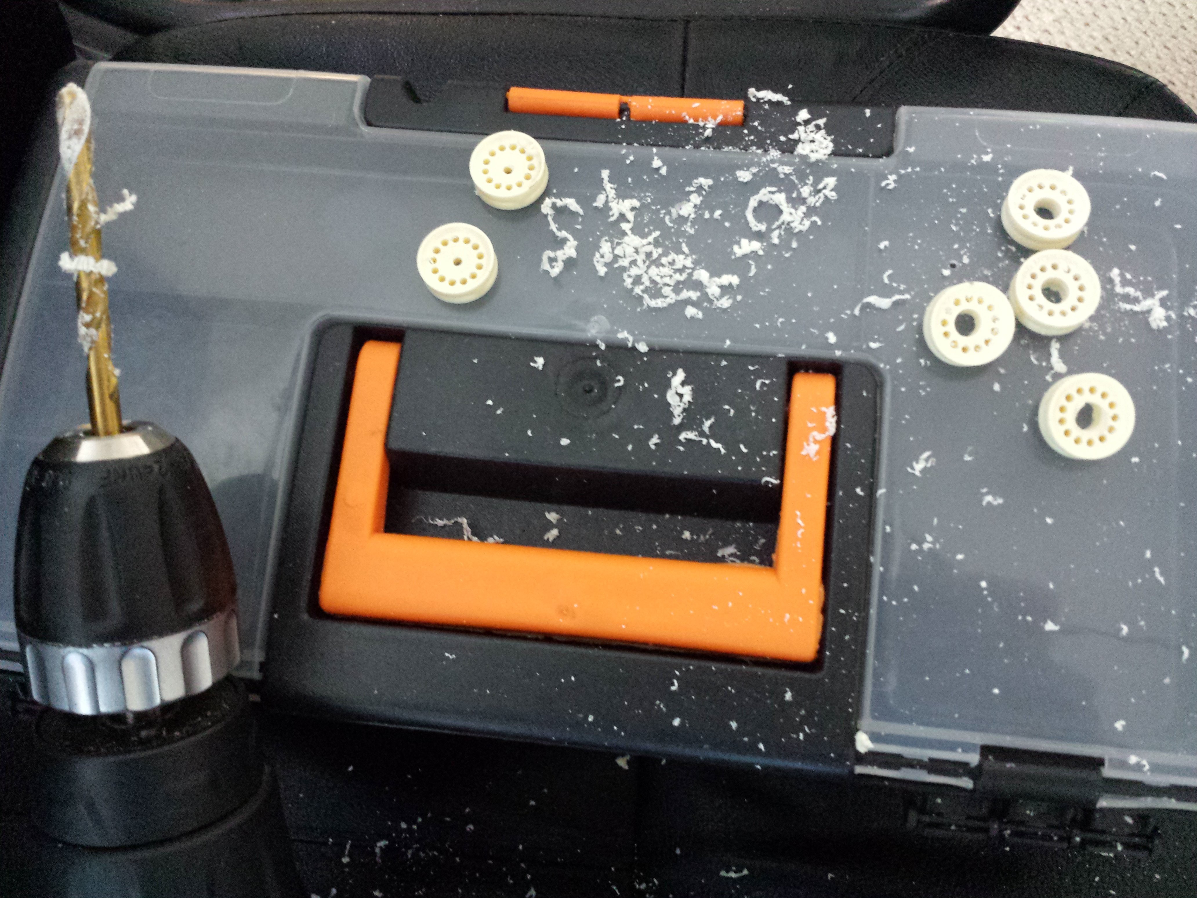
05/12/2015 at 02:41 • 0 commentsAs a result of my findings shared in a previous log entry, I decided to drill extra holes in the 'tube cell' PCBs to accommodate the 'comma' leads. This means that I will have the option to make use of these connections in the future. I drilled these holes on a Drill Press [so much easier!] without marking exactly where they should be, and reckoned the size of the holes would accommodate for inaccuracies in position.
![]()
Next up, I soldered in the pin headers for the 'tube cells'...
![]()
![]()
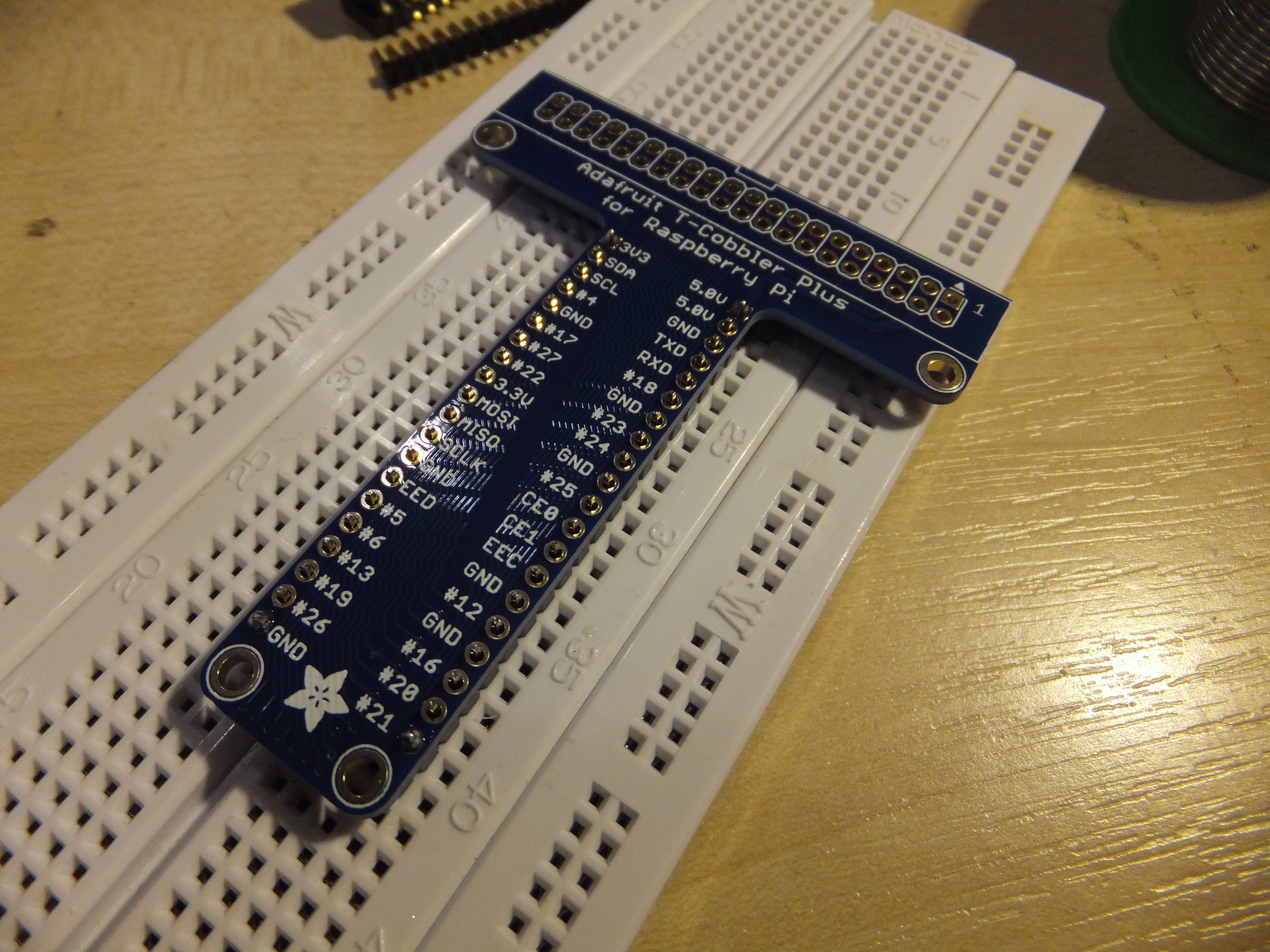
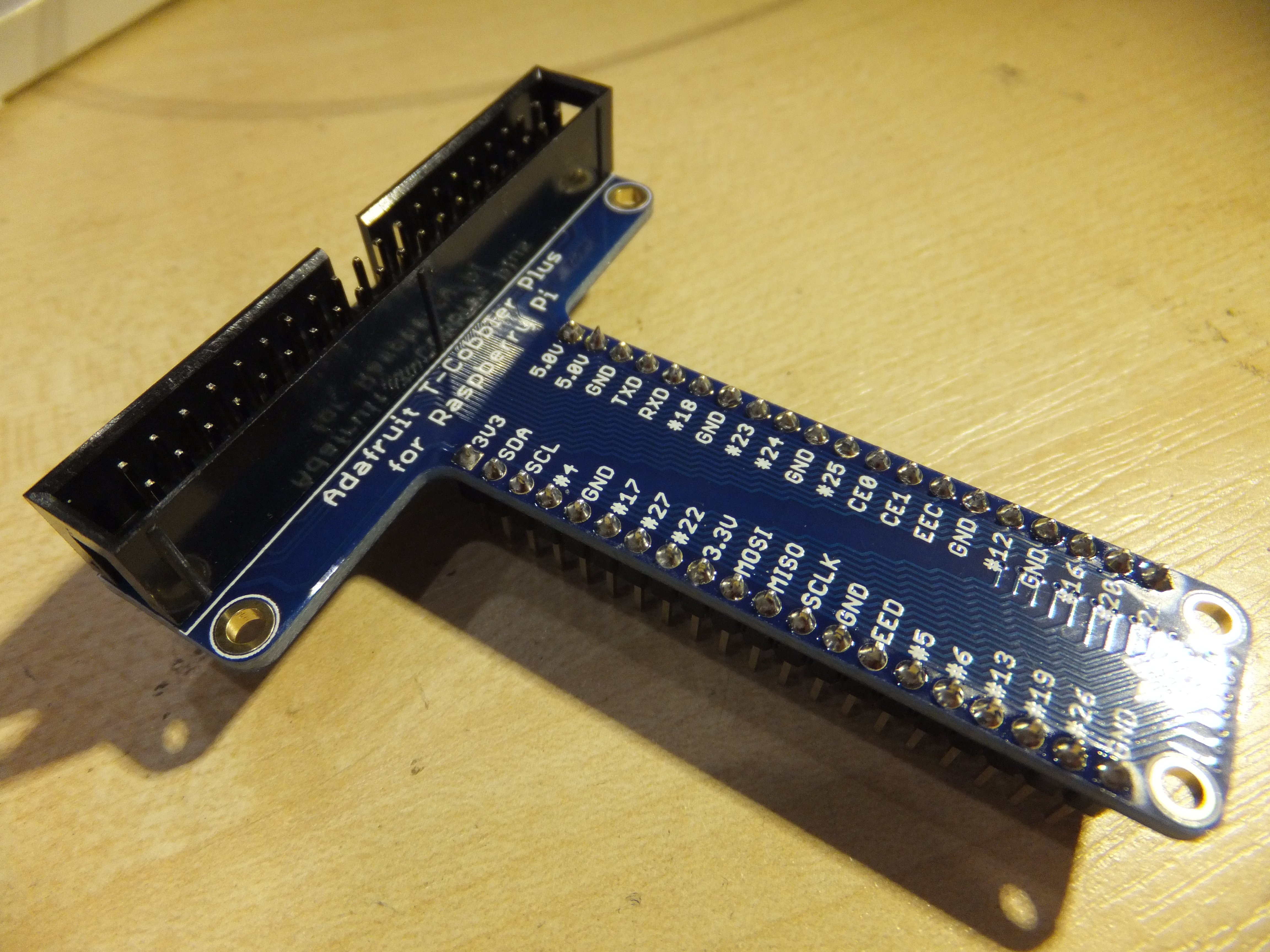
...next, pin headers and a ribbon connector on the Adafruit T-Cobbler Plus...
![]()
![]()
...and finally, the pin header on the HV Module...
![]()
...all in all a good evening's work - finished off with a pint in the pub :)
-
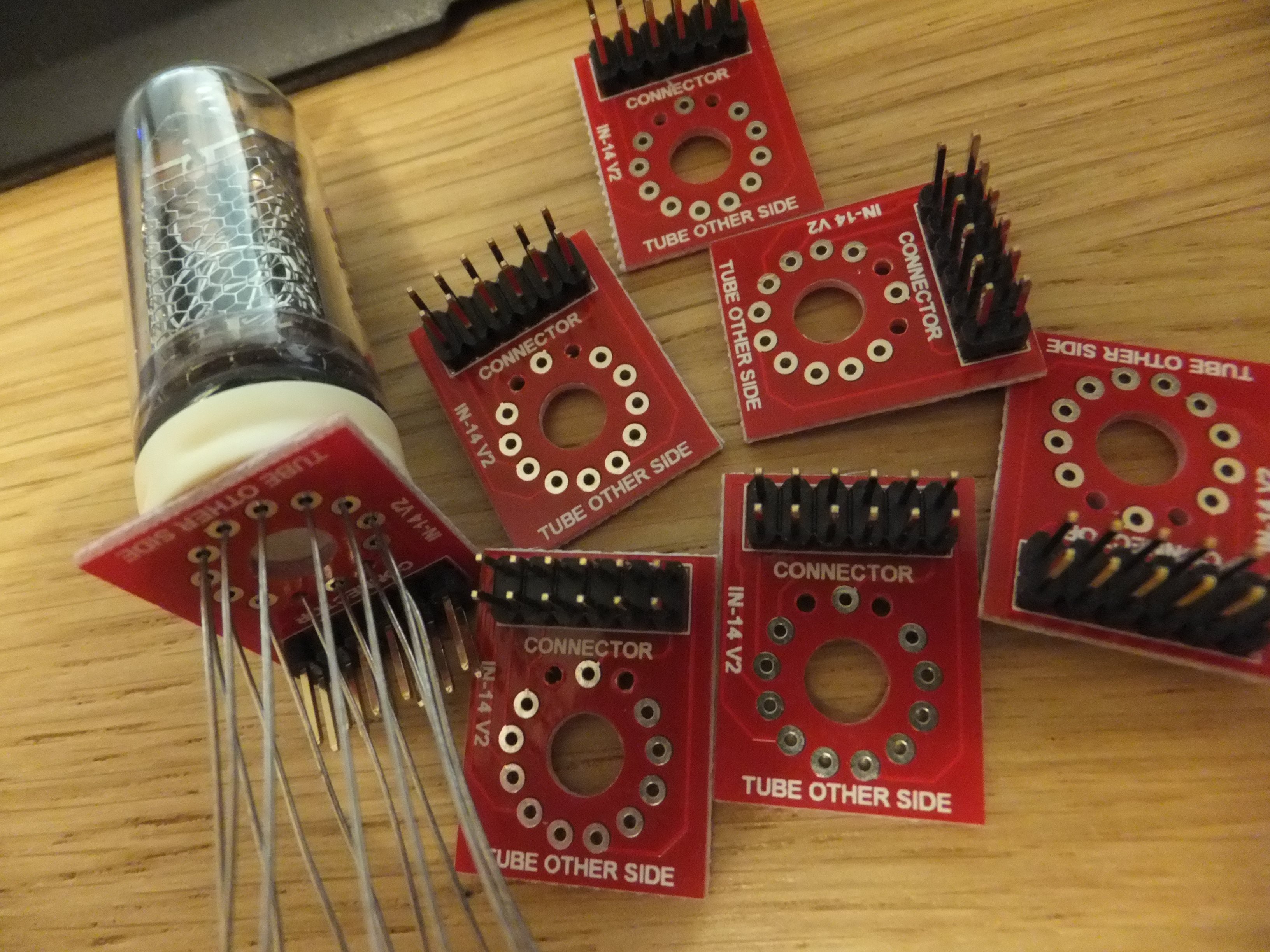
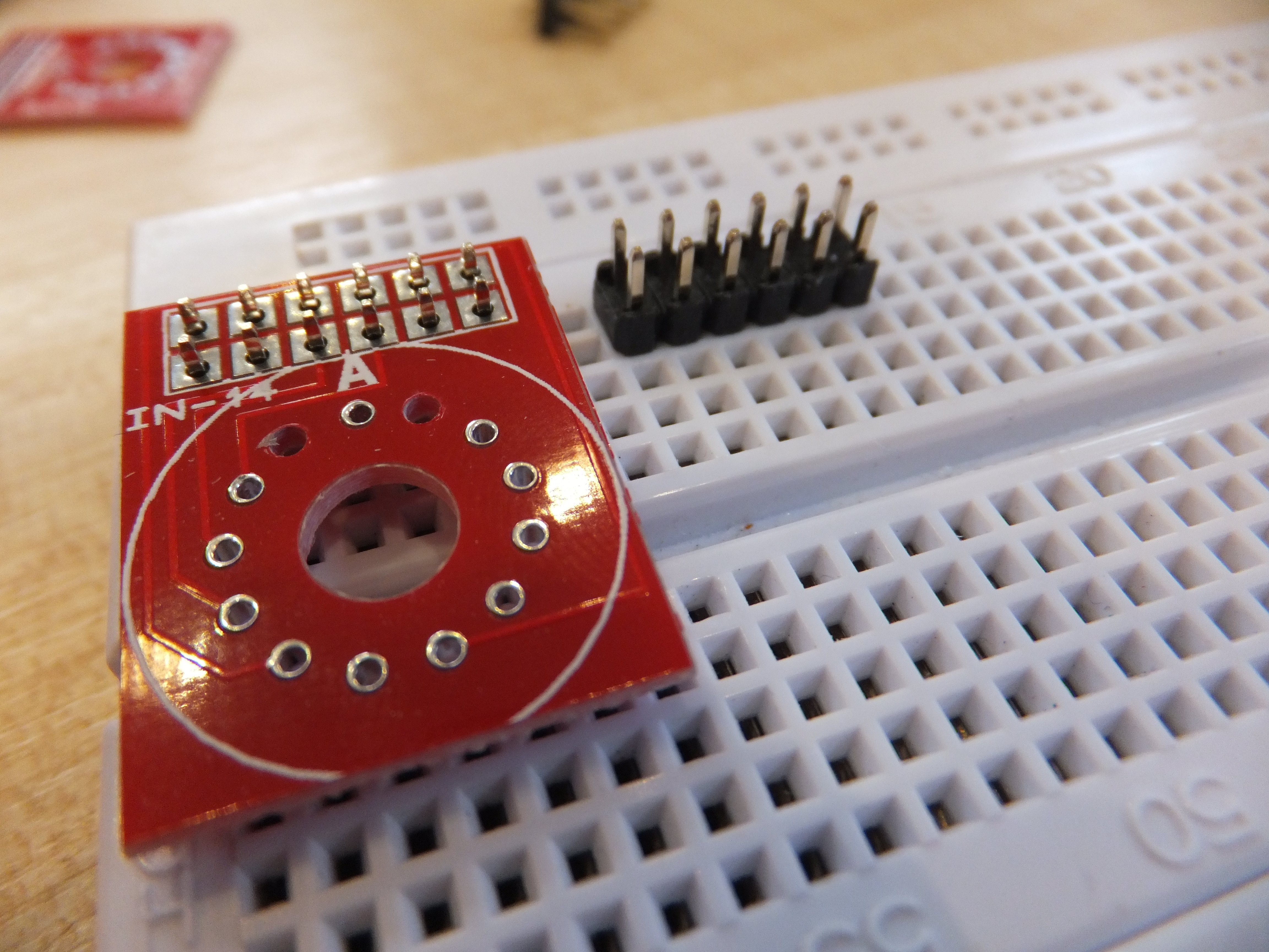
Figuring out the IN-14 Nixie Tubes and Break-out Boards
05/12/2015 at 01:41 • 0 commentsI noticed that the supplied break-out boards ['Tube Cells'] were missing a couple of holes for leads that exist on the IN-14 tubes. This initially had me thinking that I'd been sent the wrong parts by mistake, but the Silk Screen definitely said 'IN-14', so once again I started digging around the PV Electronics site for information about soldering the IN-14 tubes to these 'tube cells'. The answer came in the form of the Nixie QTC Assembly Instructions [p21].
The instructions tell you to clip off the two leads either side of the Anode, which got me to thinking what those two leads were for. After a bit of hunting on an Image Search, I found a pinout diagram that shows the pins as 'comma' aka 'decimal'. The tube cells don't accommodate for these (there are no connections to the pin headers), and I assume that this is done for all tubes used in this 'tube cell' standard.
![]()
I'm probably going to drill holes in the 'tube cell' PCBs so I can have the option to re-solder the tubes into a break-out board that supports the commas in future.
-
Figuring out the HV Module connections
05/12/2015 at 01:12 • 0 commentsPV Electronics were kind enough to sell me an HV Module to power the Nixies, which is not yet officially for sale on their web store.
NOTE: Nixies require about 170 volts to 'strike' the tube and make the [I assume] Neon gas glow. You can't just put 5 or 12 volts in and expect things to happen :)
I subsequently realised that I needed to find out how on earth this thing should be wired. After a bit of digging around, I found the answers I needed in a Schematic included at the end of the 'Spectrum 18' Assembly Instructions on the PV Electronics site.
![]()
From this diagram, I could see that the input power needed 12 volts, and that pin 4 (titled 'Radj' on the PCB silkscreen) needed a fixed resistor [6.8k] and a variable resistor [1k] to trim the HV output. After a quick hunt around the 'net, I also learned that 'SHDN' was short for 'Shutdown'.
-
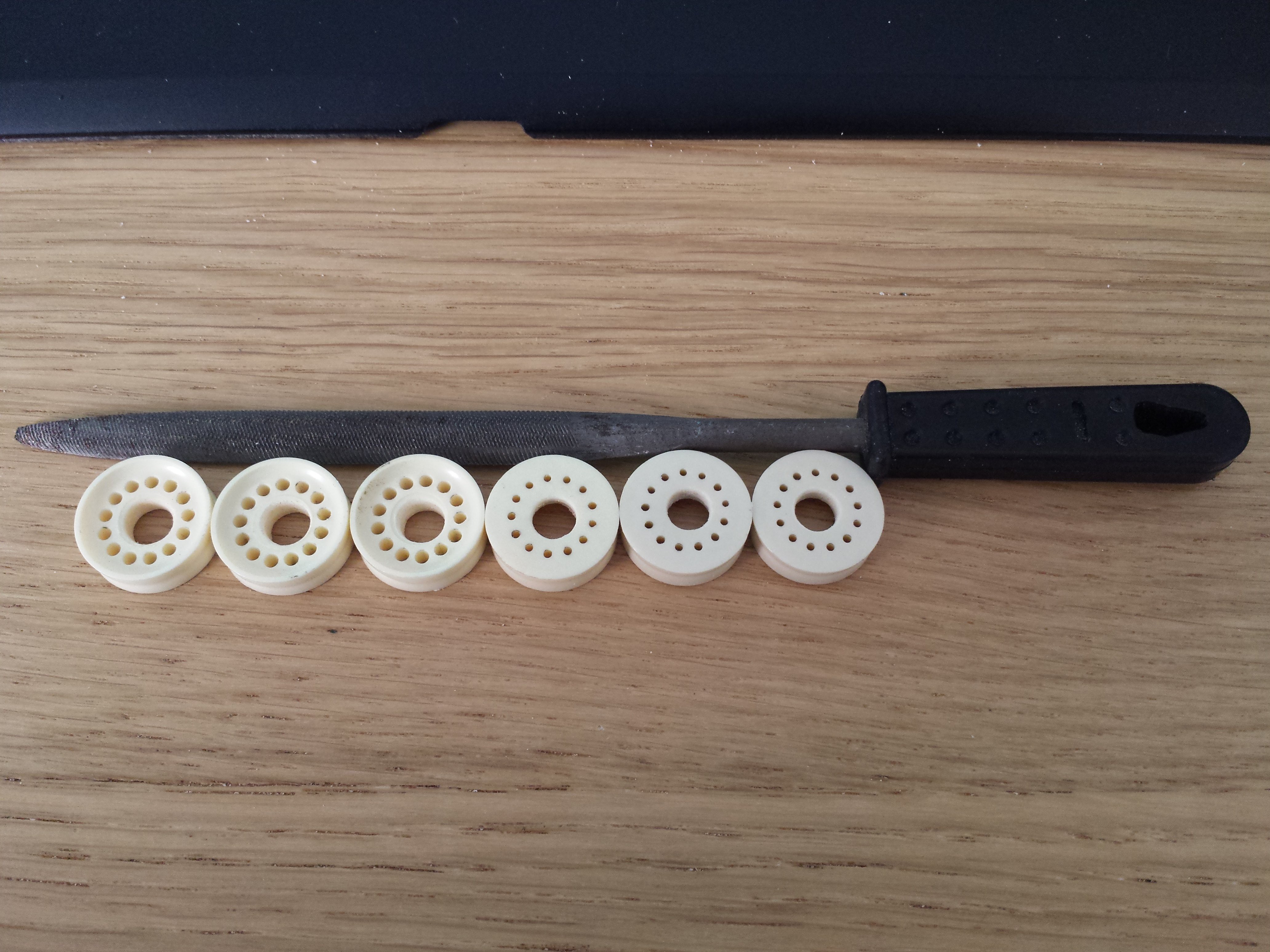
Modifying the Nixie Tube collars
05/12/2015 at 00:42 • 2 commentsI decided to keep the plastic collars on which the tubes sit, but also wanted to option to shine an RGB LED up through the centre of each tube. First task in this case was to drill a hole in each collar.
![]()
A bit of finishing was required to get rid of plastic burrs.
![]()
Nixie 'Display of Things'
Use a combination of six Nixie tubes with a 16x2 LCD display and Pi2 with Adafruit Proto-Perma HAT to display information.