Close
0%
0%

32-bit Audio Effects Unit

This is a 32-bit audio effects processor which combines several menu-selectable effects into one unit.

Similar projects worth following
I'm using a TI TLV320AIC3204 codec and a PIC32MX150 to create a multifunction guitar effects unit. An OLED and rotary encoder provide menu selection. So far I have 13 effects programmed (pitch shift, Flanger, echo, chorus, etc.) and an E2 tuning tone, and I still haven't explored the TLV320's filters and onboard goodies. The '3204 is a stereo device, so the second channel can be a mic/aux input, a noise gate input, a pre-programmed sample output ... I'm open to suggestions.

When I get this thing boxed up, I'll have to get some guitarist acquaintances together, and get opinions on which effects work and which ones suck! Until then, this thing will be one big scrollable menu of guitar effects.

The TLV320 is currently running at 64K 32-bit samples/sec; samples are passed via SPI. The PIC32 controls the TLV (via I2C), monitors the pedal position sensor (AS5055) once every 64 samples, and sends graphics to the OLED.

I chose the AS5055 magnetic position sensor for two reasons: 1) I wanted a non-contact solution to avoid wear, and 2) I found I needed better resolution than I could get out of a potentiometer and a 10-bit ADC. The AS5055 works as advertised, and the magnet alignment issue I was having was solved by using a different type of magnet.

As of now, the 13 effects I have are: 2 octave Pitch Shift, 1 octave Pitch Shift (for finer control), Flanger, Clipping, Soft Clip, "Sag", Chorus (dry plus 1-3 voices), Echo, Harmony(dry+2 voices), Harmony(dry+1 voice), BitCrush, Static, FeedBack Comb filter.

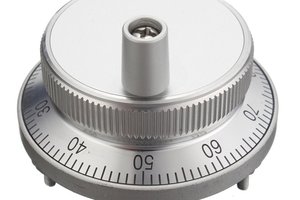
I'm torn over what feature to use when you push in the encoder shaft; I can have it switch-on/switch-off an 82.45Hz tone for E2 tuning, or just Mute the outputs until it's released.
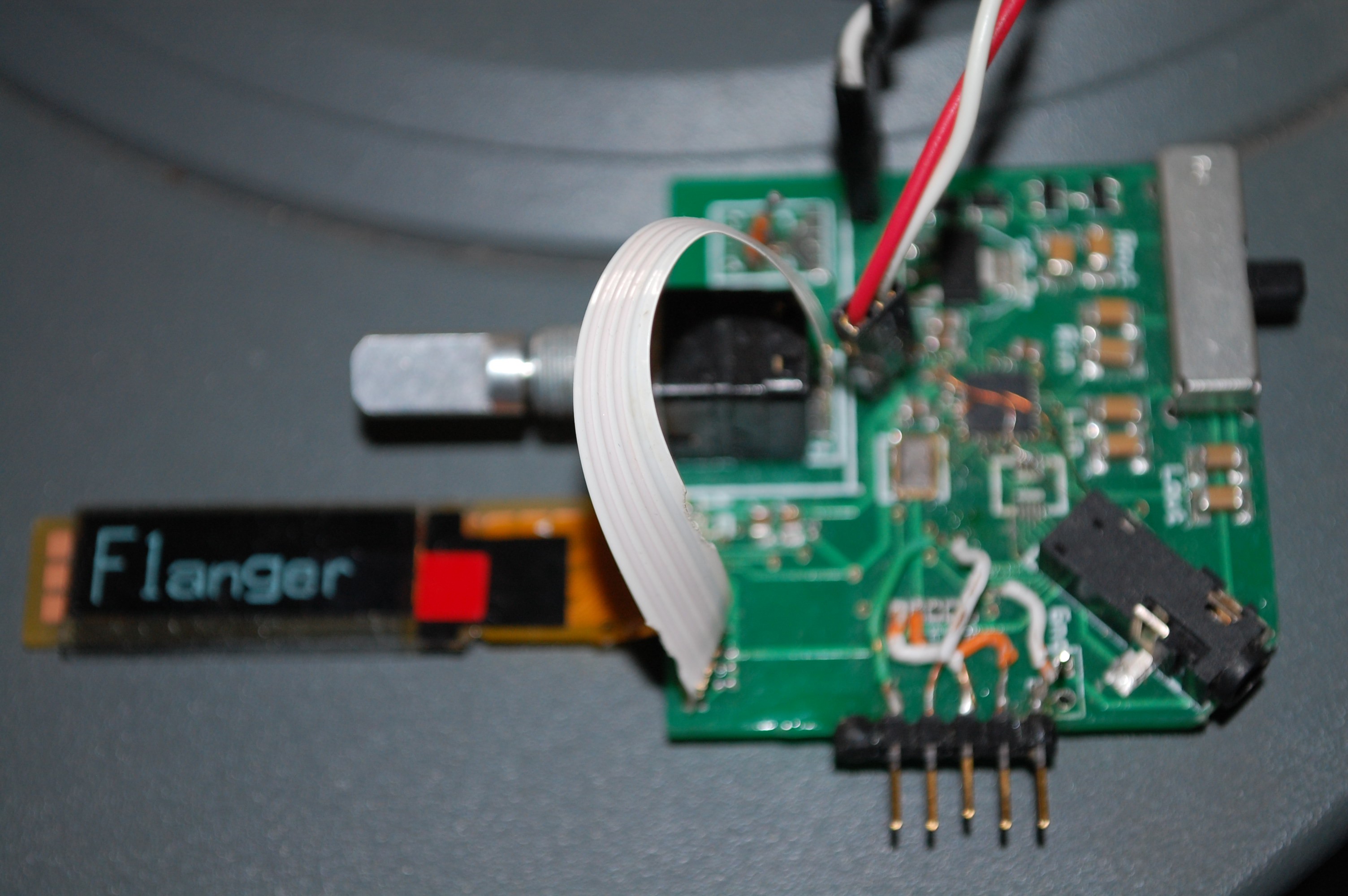
The image shows the working unit; my rev1 board has the encoder and pedal sensor all on one pcb; I just received updated pcb's with the encoder and sensor separate. The 5-pin ICSP header along the bottom was glued on for prototyping.

So for now, I have 3 tasks left: AS5055 magnet alignment, getting my 'theremin' effect working, and designing a case.

6/25: Forget what I said about the AS5055 having a small sensing area; i just tried a small cabinet latch magnet I had laying around, and it works MUCH better than the bar magnets I was trying before.
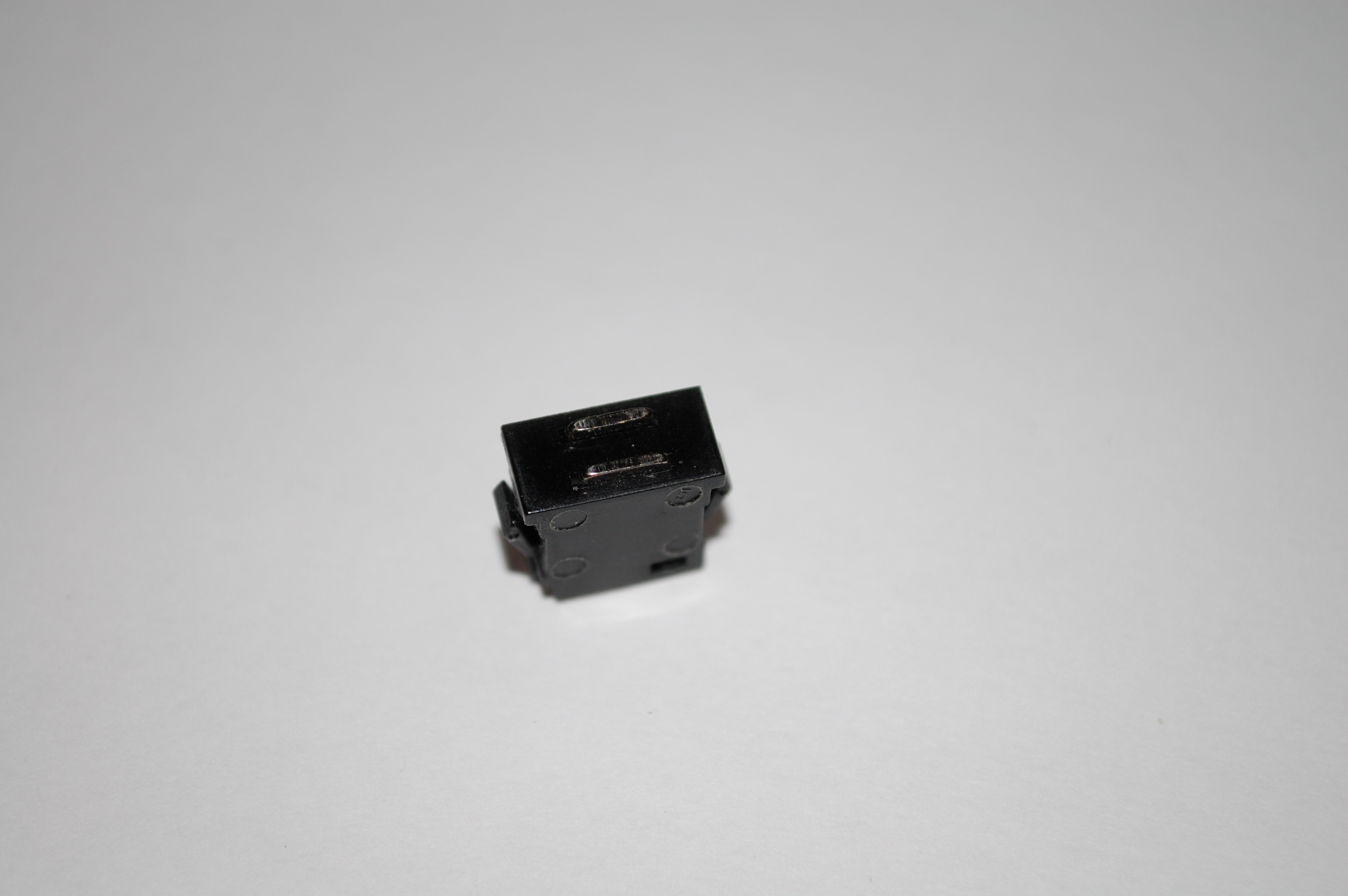
One problem down!

7/12: Ran across a description of a Sample & Hold; 13 lines of code later, I have my 15th effect. I'll have to play with the hold time to find the best sound.

7/22: Well, after a few days tracking down a bug caused by combined misreading of the PIC datasheet AND leaving some test code un-commented-out, I finally saw my waveforms change smoothly in response to the pedal magnet. YES!

Tonight I'm off to the local makerspace (Sask TechWorks) to see about printing a case and components.

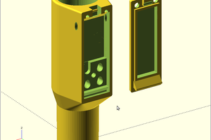
7/28: after various fits and starts, I got a 'learning prototype' printed - as in '"now i get to see how bad my Sketchup skills are". :)

Being that it was a flat box, the corners pulled up - oops, lesson learned. And I STILL can't figure out how the Makerbot printed several centimeters of (millimeter-sized) horizontal beams WITH NO SUPPORT STRUCTURE! How'dtheydothat?

Anyhow, in spite of the pulling, the important areas printed fine, and showed me some changes that need to be made for ergonomics. All in all, for a first pass, I'm satisfied. Tonight it's back to the 'space for more...

  • The Hunt Continues

    randy.day07/29/2015 at 22:53 0 comments

    7/29: I printed up a small jig to test pedal sensors. It lets me turn a magnet by hand over the sensor; this helped me pinpoint a not-bug in the position sensor coding. It turns out the AS5055A output is 0-1FFF (13 bits) over 360 degrees; the datasheet must be referring to 12 bits over 180 degrees. Anyhoo, the position sensor is tracking fine now.

    7/30: The last bug has been obliterated, all scope waveforms track on all effects - time for the acid test! I hooked up a guitar to the input, and the output to the Aux In jack of a cheapo countertop stereo, and ... a split-second of sound, and <pop> no audio. Power off/on, a split -second of sound, and <pop>. WTF?

    I hooked in the oscillator I was testing with, everything's back to normal; at least nothing blew. 'Sample/Hold' and 'Theremin' sound totally *awesome* as you move the magnet! Most of the rest work as expected, but Chorus seems a bit odd; then again, it could be that I'm getting cancelling effects from a single-frequency input tone.

    After that, I tried the guitar again - NOW it decides to behave! Maybe I'm sitting too close to the speaker, and feedback tripped something.

    All in all, it's working, just not reliably. More testing to come.

    8/6: Came across a description of something called 'Track & Hold' in an essay on sample & hold circuits. It is now effect number 16 on the device. Given that the selector is a 12-position encoder, that's 1-1/3 turns of the knob to scroll through the list. I'm declaring a moratorium on new effects until I get some opinions on what to cull. My Carpal Tunnels will thank me later. Plus, as Brian mentioned in the review, I need to focus on the mechanical side of things.

    8/11: My first print of a foot pedal mechanism came out with a weak layer through everything; the plastic is pale, with visible gaps between layers. Pieces fall off at the merest touch. Still, it gives me some insight into what might and might not work.

  • Music can change the world...

    randy.day07/29/2015 at 04:35 0 comments

    7/12: Ran across a description of a Sample & Hold; 13 lines of code later, I have my 15th effect. I'll have to play with the hold time to find the best sound.

    7/22: Well, after a few days tracking down a bug caused by combined misreading of the PIC datasheet AND leaving some test code un-commented-out, I finally saw my waveforms change smoothly in response to the pedal magnet. YES!

    Tonight I'm off to the local makerspace (Sask TechWorks) to see about printing a case and components.

    7/28: after various fits and starts, I got a 'learning prototype' printed - as in '"now i get to see how bad my Sketchup skills are". :)

    Being that it was a flat box, the corners pulled up - oops, lesson learned. And I STILL can't figure out how the Makerbot printed several centimeters of (millimeter-sized) horizontal beams WITH NO SUPPORT STRUCTURE! How'dtheydothat?

    Anyhow, in spite of the pulling, the important areas printed fine, and showed me some changes that need to be

    made for ergonomics. All in all, for a first pass, I'm satisfied.

    Tonight it's back to the 'space for more...
View all 2 project logs

Enjoy this project?

Share

Discussions

leesiujoeng wrote 03/06/2020 at 03:47 point

Nice to meet you. Recently, I was studying a guitar case of STM32 and codec. But I don't know how to configure codec. Can we communicate with each other? Thank you very much

  Are you sure? yes | no

randy.day wrote 08/14/2015 at 16:52 point

Well, after a week of being unable to login to HaD.io, I'm back.

lombardo.guitar, I recall reading about pedal placement somewhere in the distant past. This unit could make that a bit tricky, since it has both time-based and distortion effects, Add to that, when the unit is installed on/in the guitar itself, it pretty much becomes first in line. Ah, well, rules are made to be broken!  :)

  Are you sure? yes | no

lombardo.guitar wrote 08/08/2015 at 14:52 point

Just a bit of knowledge for an old guitar player, put tone type FX (wha, filters) before the distortion block, any time based (echo, reverb) after the distortion block.  It makes for a smoother sound IMO.  As we all know these are not hard fast rules, sometimes you want to distort the echo instead of echo the distort!  Neat build!

  Are you sure? yes | no

randy.day wrote 07/09/2015 at 23:07 point

The CTMU is on the long-range to-play-with list; too many other things OTG.

The AS5055 is more expensive than the micro, but it does measure rotational angle (which I need), works asynchronously, and there are no LC oscillators to potentially interfere with pickups. I will be keeping your position sensor in mind for other projects, though; hey, maybe you should enter it in the Human Interfaces contest.

  Are you sure? yes | no

randy.day wrote 07/07/2015 at 21:52 point

Sorry, Lightning Stalker - a logic analyzer is something I've been wanting for some time now.

  Are you sure? yes | no

randy.day wrote 07/07/2015 at 21:47 point

Thanks Jithin! This could be an active pickup - I hadn't thought of it that way. With a side order of effects! The board is certainly small enough to fit in a guitar body & that is a future project. Just to clarify: the magnetic sensor reads the pedal position; the menu selector is a regular mechanical encoder. The OLED is a Visionox M00538, 128x32 pixel; quite a nice display, but I broke a couple by flexing the ribbon cables too much.

I had thought of using the encoder-push to set parameters, but on reflection I decided it would be a lot of push-turn-push wrist and thumb action, which could get frustrating for users. Not to mention the menu/submenu spaghetti factory it creates in the code. I'll keep it simple for now...

  Are you sure? yes | no

Jithin wrote 07/08/2015 at 10:58 point

Oh shoot.  My bad.   But mechanical parts often cause headaches in the long run.

Have you considered using the CTMU module of your PIC?  you can implement a bunch of buttons/sliders, and quite elegantly too.  e.g. , a simple wedge shaped sticker on the guitar can serve as an input slider. The CTMU shares the ADC, so you might end up with a slight glitch each time you sample the inputs.
Isn't the AS5055 quite expensive? Here's an alternate solution - https://hackaday.io/project/5971-python-powered-scientific-instrumentation-tool/log/19731-non-contact-short-range-position-sensing

All you need is an LM311 (<1$) , a coil, a board pin, and a couple of  capacitors and resistors. You'll get more resolution than what anyone can manage to set with his foot on a pedal. Schematics are on the main project page.

  Are you sure? yes | no

The Lightning Stalker wrote 07/07/2015 at 20:53 point

Want to trade for the logic analyzer?

Have some 2.5W laser diodes

  Are you sure? yes | no

Jithin wrote 07/07/2015 at 17:31 point

Nice work!
More affordable pedals need to hit the market. Have you tried making an active pickup? I'm sure you could fit the PIC and the TLV320 inside an electric, thereby ending up with a guitar with built in effects too \m/
Nice choice on the magnetic knobs.  I've an effects pedal whose mechanical encoders  occasionally decrement values instead of incrementing, because they're pretty worn out.

As for your confusion on what to do with the push button feature of the shaft, might I suggest implementing a menu of effects?  To clarify , a short push will allow you to tweak the parameters of the selected effect, such as delay time, flanger's speed etc. Long push can activate the tuner.
Where did you source the long OLED from?

  Are you sure? yes | no

randy.day wrote 06/23/2015 at 23:21 point

Bruce, your MMB manuscript has been browsed and bookmarked. Your envelope generator is great, and I'm already using a wavetable.

  Are you sure? yes | no

randy.day wrote 06/23/2015 at 21:18 point

I hadn't heard the term 'harmonizer' until you mentioned it. From what I read online, it's adding pitch-shifted signal to the dry input. I have a couple versions of that already (1 voice and 2 voice). Modulating L->R or R->L could be interesting: amplitude modulation of L/R based on the signal strength of R/L seems doable.  I read up on frequency modulation, and it's a bit more algorithmically intensive, but I'm not sure that what comes out would be musical!

I have both chips set to use Right-Justified format, simply because that was the setting in use when the TLV finally gave me an actual signal output, after <mumble> days of trying different settings. Now it's a matter of "it ain't broke, don't fix it".

I've thought about using the TLV320's onboard filters for things like wah, phaser and hi/lo/bandpass, but that's a lot of parameters to push over the I2C channel if I want to make them dynamically variable. I just yesterday considered using interrupts (which I've never used on the PIC32) to synchronize all the transfers, so that's now back on the list.

Ah, feature creep, thou art the Sauron to my Frodo...

  Are you sure? yes | no

Adam Fabio wrote 06/23/2015 at 05:12 point

Nice work Randy! I wonder if you could do some kind of harmonizer thing - like using the guitar to modulate a voice on the other side of the stereo input.  It might be a lot to ask of the PIC. Are you running with hardware I2S?

  Are you sure? yes | no

Similar Projects

Does this project spark your interest?

Become a member to follow this project and never miss any updates