 ganzuul
Purpose & Design goals
The purpose of this system is to enable efficient selective sintering of transparent and reflective materials such as glass and steel. To reach this goal I'm designing a compact, high-efficiency, powerful and affordable gas laser which can operate in the mid-IR region.
State-of-the-Art and Theory
Usually in gas lasers most of the input energy is lost from the system in the form of heat conduction through the walls of the optical resonator. The existing designs of especially HeNe lasers seem to use an approach of dumping ever more energy in the system and removing the heat in a controlled manner to achieve temperature stability and beam power. These designs expose the hot lasing gas to very large surface areas compared to effective beam volume, making them inefficient.
According to the art of building gas lasers, you get very little power increase when you make the laser beam wider. This is because the atoms spend a long continuous time in the active lasing region so they get little opportunity to reset their energy levels, which is needed to ready them for emitting more photons. Using a thin beam and a very long waveguide is the efficient approach, but folding the laser beam in a zig-zag pattern inside the optical resonator through various topological means has not given as much space saving as one might expect. These existing solutions are brilliant in their own right, with very robust geometry often involving convex mirrors, so that when the device undergoes thermal expansion the beam does not attenuate.
Home-built CO2 lasers often have a beam which fades in and out because of this. To get a stable beam you need to de-couple the mirrors. Desktop HeNe devices used for education tend to use an elaborate and very costly rig of machined parts to do this.
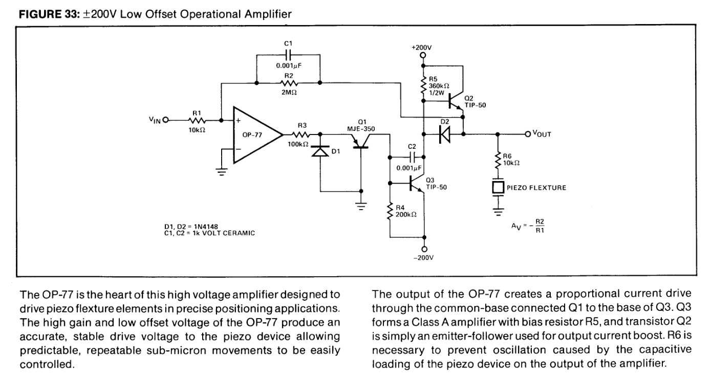
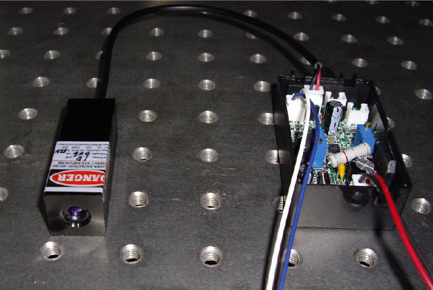
This project will hack high-voltage amplifiers to drive common piezoelectric discs as actuators, and mount the mirrors to the actuators. There are two pairs of parallel mirrors at a diagonal to the other pair, with one pair kept at nλ and another at nλ ± ½λ (The latter is also referred to as 'half-wavelength mirrors' in this document.). This creates a tightly-folded beam path which yields high efficiency and high beam power since the ratio lasing region volume vs. resonator surface area is large. This configuration also reduces device size vs. beam power. The solid medium version of this laser is called total-internal-reflection face-pumped laser (TIR-FPL), where the laser is confined to the medium by angle and index of refraction, similar to how an optical fiber works. In TIR-FPL the parallel surfaces are still a problem because even though the index of refraction lets light perpendicular to the surfaces pass right through and no mirrors are used along that path, some of the light is still reflected. These reflections are called 'parasitic oscillations' in slab lasers. The patent US7505499 assigned to Panasonic Corporation postulates no parallel polished surfaces to address this issue. We of course solve the same problem by keeping the parallel mirrors and detuning them.
If you put two mechanically coupled end mirrors in parallel against each other, making an 'infinity mirror', then thermal effects will make them sometimes lase and sometimes not as the optical resonator heats up and expands. This happens because the light as they constructively interferes and destructively interfere since this effect is controlled by the distance between the mirrors. Mirrors separated by nλ ± ½λ, meaning a length of any number of full laser light wavelengths with a half-wavelength either added to subtracted to its length, will always destructively interfere and cancel light amplification. Mirrors separated by a number of full wavelengths, eg. for HeNe 632.8 nm x some large number, will always increase light amplification, adding more and more intensity to the laser beam as the process of Light Amplification through Stimulated Emission of Radiation does its thing.
Stimulated Emission...
Read more »


 FabLab München
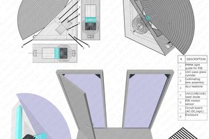
 37
37
 Dylan Bleier
Hold on… terraform Venus by HEATING its atmosphere? Isn't it hot enough already?