Yann Guidon / YGDES
-
Crystal oscillator with MOSFETs (new episode)
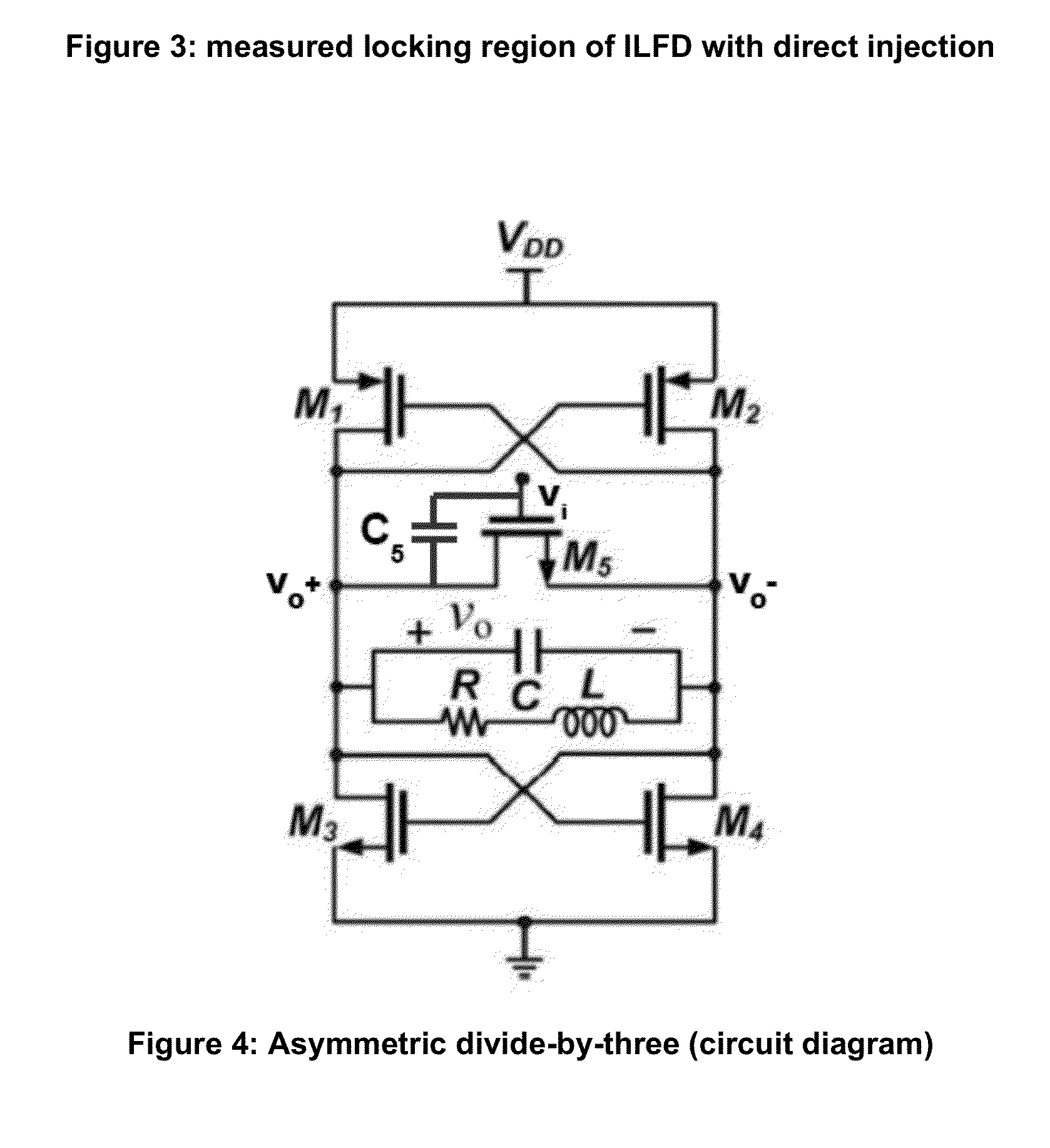
05/23/2016 at 02:47 • 0 commentsWhile researching a different subject (divide-by-N without flip-flops), I found the following drawing :
![]()
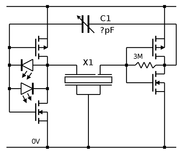
This circuit is actually a high frequency tuned oscillator that gets synchronised to an incoming signal. Now, forget the MOSFET M5 and look at the RLC network in the middle. Doesn't this look like the equivalent circuit of a quartz crystal ? And the MOSFET are actually cross-coupled inverters and there is no coupling capacitor (but one feedback resistor)... Is this the ideal circuit ?
mind: blown
More informations about Injection-Locked Frequency Dividers at http://www.ece.rochester.edu/projects/laics/ilfd.html
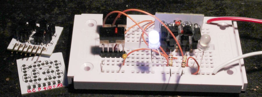
Of course I have to test it.
My first test : the circuit oscillates. At 5V. At about 7MHz. The crystal has no effect and the shunt/feedback resistor must be very low. And there is a lot of 3rd harmonics, depending on the voltage ...
-
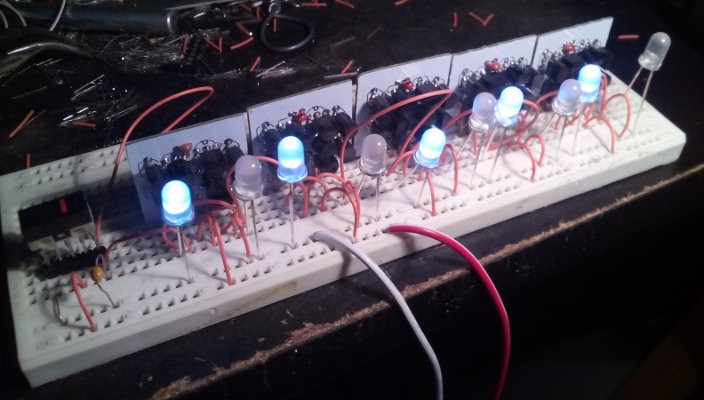
Crystal oscillator with MOSFETs and LEDs
05/19/2016 at 17:05 • 7 commentsFollowing the last log in the series (Yet another MOSFET oscillator) I finally wired the circuit that I imagined at the end of said log.
![]()
The good news : the LEDs shine when the oscillator is locked, not before.
The bad news : the operating voltage is higher and lock is around 3.6V.
But I think I am onto something... The LED don't act as limiters, contrary to my expectation, but they react well to lock. The light also depends on the C1 feedback capacitor.
Lock is also affected by the feedback resistor (things become interesting around 100K-200K) and it affects the driver's waveform, the LED are fully lit when the output is square-ish.
I need to find a way to lower the working voltage and smooth the waveform. Probably with only BS170s but the BS250 are required for correct biasing.
One solution is to remove one of the BS250 but provide the biasing from the other complementary pair through a very high value resistor (>3MΩ) across the feedback capacitor or the quartz. Assuming that the tempco of all the transistors is the same, only one BS250 is necessary to bias the other BS170s. But which BS250 should be removed ?
- The sense side seems to be a good candidate. In the classical circuits, the crystal is usually in parallel with a very high value resistor to bias the circuit so it should work. An adjustable resistor on the drain will set the gain, which we don't want too high.
- The drive side has the LEDs and its symmetry assures a symmetrical waveform. A feedback resistor is required too, between the drains and the gates.
The parts count shouldn't increase.
I might have found one critical parameter of the crystal : the series impedance might be around 75KΩ. The bipolar circuits work despite mismatch but even with 3 MOSFET, it's very hard and I can't find a configuration that starts up below 3.3V. OTOH the remaining 10TFF act weirdly above 3.1V...
PS: when the quartz is overdriven (like with a full-scale square voltage), I can actually hear the faint whine. It is not only visible, but also audible !
Unfortunately, this emission of energy is not desirable at all.
Ooops, I realize I did all these tests with the 8KHz quartz, not the 18KHz quartz...
-
Testing the KCL structure
05/19/2016 at 12:56 • 0 commentsThe even newer structure (that I named after the culprit) works with a very different frequency, but 3600Hz is not a total stranger: it's a divisor of frequencies that have been used in other projects.
I can already test the electrical characteristics with the 32768Hz generator and make sure the edges are clean with the 'scope. But the Rb source is broken and I need something to (roughly) calibrate the 18KHz resonator.
By a nice coincidence, 18432=1024×18. I just need to find a 18432KHz canned oscillator and feed the signal to a 74HC4040. I have a huge stock of 4040 (from the #Discrete YASEP ebay binge) but I used all my canned oscs in PIC circuits that need to speak serial.
Another happy coincidence : 3600×1024=3.6864MHz, which I have also used (in #Discrete YASEP too). And it doesn't need a ÷5 predivider.
-
The KCL structure
05/19/2016 at 01:16 • 0 commentsAfter I sketched The HMS board, @K.C. Lee made a pertinent remark about another use of these boards for dividing the 18KHz source down to 1Hz.
Two HMS boards divide by 60, each, or 3600. Only a factor of 5 is needed to get 18000Hz. This reduces the overall complexity but increases the parts count (which I have been very careful to keep low... until now).
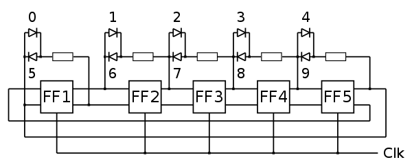
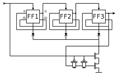
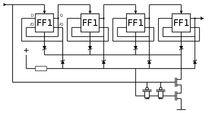
The other problem is how to implement a ÷5 predivider. I reused the ideas of Divide by 15 to create the following diagram:
![]()
FF1 and FF2 create a divide-by-4 counter and FF3 registers the overflow of FF2. The counter goes through the states 000, 001, 010, 011, 100 then during the next cycle, the latch at the bottom (with a pair of PFET and a pair of NFET) forces the reset during half a cycle. The state should go back to 000.
Actually, FF3 might not be necessary because it's used as a sort of set/reset latch that adds a one-cycle delay. Maybe I can save a few transistors.
In fact no because the latch is synchronous on one edge of the clock signal so at least one "charge pump" is required.
-
The HMS board
05/18/2016 at 21:39 • 0 commentsI was stuck yesterday but the seeds have been received today ! I can work on the next PCB :-)
I have found a pretty versatile solution that does all the counters for hours, minutes or seconds, with a single 100mm×100mm PCB. This exploits the similarities so we only have to deal with a little quirk for the hours but the same PCB can be used in 2 configurations : count to 60 or count to 24.
In all the cases, there are 8 10TFF modules, that use one half of the PCB. The other half is a rectangle that holds the modules and wires them together. The whole set is very easy to manufacture in any PCB house.
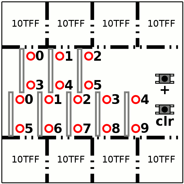
The panelized boards are shown below:
![]()
On this board, the LED are red but the color can change. Actually I'd like to have red for the hours, green for the minutes and blue for the seconds (and something else for the tens of seconds ?)
The board uses the same 10-stages Johnson counter for the bottom decade, the upper counter can be wired in two different ways :
- for the seconds and minutes, a 6-stages Johnson counter (with all the 6 LEDs plugged)
- for the hours, a 3-bits shift register (3 LEDs are wired)
The difference is how you wire the 3×10TFF modules:
- The loopback is either twisted (Q and /Q are switched) to make a regular or twisted shift register (thus doubling the number of states)
- The reset status is all 0s for the Johnson counter, or 100 for the regular shift register.
The above changes are applied by soldering the proper jumpers, or diodes on one of the modules.
(Update: well, no need to hack the diode, just rewire Q and /Q, D and /D, a few jumpers !)
The hour configuration must also reset the whole board when it reaches the value 24, so it must actually detect the value 23, latch it and pull the reset down when the next clock pulse is received. This is similar to the circuit explained in Divide by 15 but with different conditions, and a REAL CMOS AND3 gate to prevent power losses through the pull-down resistor.
Now, considering that the LEDs will draw "some power" anyway, a 1MΩ resistor will not significantly affect the general consumption. The hours don't change fast so a high RC time constant is possible.
-
New 10TFF layout
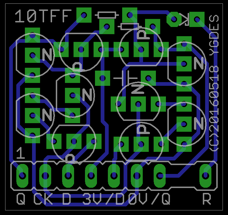
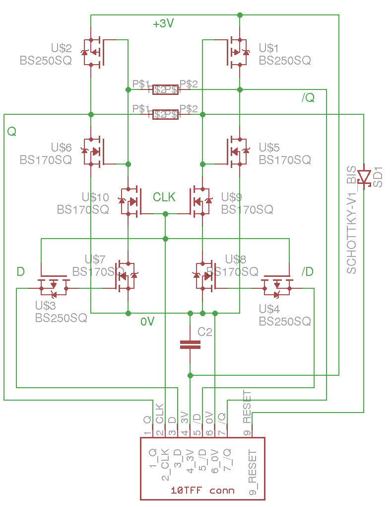
05/18/2016 at 04:03 • 0 commentsLearning from the mistakes of the first run of PCBs, here is the new layout.
- Added a reset pin
- Added a diode for the reset (marked as Schottky but can be germanium)
- Diode can be soldered in either direction for set or reset function (saving some room on the main board)
- Added a decoupling capacitor
- Added a proper connector (it's now a component in EAGLE so it can be reused to design the main board)
- The connector is keyed to prevent reverse/shifted insertion
- Fixed the drill diameters (the connector can be inserted with no force)
- Changed the pad shape to square for enhanced solderability by beginners
- Pinout compatible with v1
- Still no jumper
- Still 100% single-layer compatible and almost suitable for home etching
- Still fitting in a 25mm square
I've had to play a bit with placement, for example the resistors : they are quite thin so the current placement is not a problem.
![]()
![]()
I have no idea when I'll be able to afford another PCB run... yes I'm that broke.
-
Divide by 15
05/15/2016 at 20:45 • 4 commentsUsing the 18KHz clock source, the cascade of dividers is more complex than with the usual 32768Hz crystals. Normally, 15 stages of division by two (15 flip-flops) bring the 32KHz input down to 1Hz. At 18KHz, a different cascade is chosen:
- divide by 8 (3 flip-flops) : 2250Hz
- divide by 15 (3 flip-flops) : 150Hz
- divide by 15 (3 flip-flops again) : 10Hz
- divide by 10 (5 flip-flops in Johnson counter configuration) : 1Hz
The divide by 8 has already been implemented.
From there the 10-states Johnson counter was rather easy to implement.
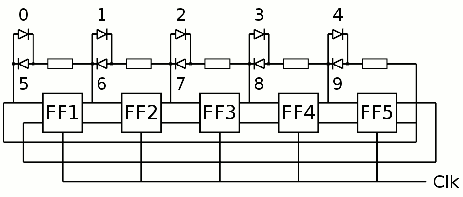
Now there is a new logic design problem to solve : how to divide by 15 ?
These divisors have been chosen because they use most of the coding space allowed by 4 bits, only one code is lost out of 16. This is pretty easy to do with a synchronous counter : detect the code 15 (1111) and trigger the reset.
Detecting the code is easy too : just use 4 diodes (or even MOSFET) wired to the right signals, add a pull-up(/down) resistor, and you have a pulse.
The problem is with the reset signal because there are many timing issues with a ripple counter. Some kind of resynchronisation must be performed.
- Either the circuit must be fully synchronous
- Or the reset circuit must be sampled.
The choice will depend of course on the complexity and parts count.
A fully synchronous circuit is possible but implementing the incrementation with discrete MOSFET is going to be too heavy. The ripple counter has this amazing property of avoiding explicit calculations, which saves many parts.
Sampling the reset signal has been done before : The 10TFF cell contains 2 sampling circuit for D and /D, made of one P-FET (a pass-gate) and two N-NET (one charge-memory and one clock-enabled pass gate).
As is, the circuit can't be reused because the body diode of the P-FET will allow the N-FET charge to be removed as soon as one of the 4 FlipFlops is cleared, which might leave the others still in their previous state. The charge must be preserved longer and the parasitic diode must be disabled. This is possible at the cost of one more P-FET in reverse with the data-pass-gate.
![]()
This way, the reset signal will be applied strongly, during one clock phase, with only 4 MOSFET, 4 (more) diodes and 1 resistor...
The fanout of the clock is almost 20 FET gates. This is why there is a 2^3 predivider after the crystal oscillator.
The reset detects code 1110, but this could actually be 111x, so we can save the diode connected to /Q of the leftmost flipflop.
Update (20160519): the power losses through the pull-up resistor can be reduced by enabling the power when the last couple of FF are "ready", through one or two BS250. This would make a diode-transistor logic AND gate...
-
My first discrete 5-stages Johnson counter
05/15/2016 at 05:27 • 0 commentsMore progress! Five 10TFF modules are now wired as a "twisted shift register":
Now I just have to re-wire the LEDs to make only one of them shine at a time.
Well, the decoding is pretty simple... Except for one little detail of course.
Back in Another display option I proposed the following diagram:
![]() But it doesn't work right. The actual wiring should be :
But it doesn't work right. The actual wiring should be :![]()
It's pretty subtle but it works. The reset state turns LED#0 on.
-
It was too easy...
05/13/2016 at 00:11 • 0 commentsI wanted to make a decade counter (like a 4017, which is the basis of this whole clock) and I soldered 5 more modules.
Then I tested them.
None of them worked.
The only difference with the first two was : the BS250, coming from a different source (from the far east, yes again...)
After a little test, it appeared that these are indeed P-MOSFET but with reversed pinout !
I had to desolder those 4×5=20 transistors and all the modules work now.
While wiring the 5-bits counter, it appeared that I did another mistake. There is no way to asynchronously reset the flip-flop to a given state. You have to solder a wire to the board. Somehow, I didn't bring the gates to the 7-pins connector !
I'll have to change that for the Rev.2 board...
Anyway I got something working tonight.
Not the desired decade counter but a 5-bits binary counter. Eh that's still something. And after I correct the above mistakes, it runs like a charm.
![]()
I have to find a solution for the reset, so I can make a reliable Johnson counter...
I can sleep now :-)
-
Testing a module
05/12/2016 at 02:44 • 0 commentsAfter soldering, the next step is to test the proper operation of the 10TFF module. I used a small breadboard, which is unusual, but I'll solder a board with performated FR4 soon, since I'll have to test tens of modules !
![]()
(this is the moment when you realise that some markings are welcome on the board to indicate the function of each pin).
Two white LEDs are connected directly to the Q and /Q outputs.
I use one SPDT push-button to steer Vcc (3V) from one data input to the other. Pull-down resistors do the rest.
The clock input uses another SPDT switch (selecting from 0V and +3V), with a capacitor for debouncing.
And the two modules are tested "good" on their first pass !
Yet Another (Discrete) Clock
I HAD to finally do this basic "exercice de style" in digital electronics, using some hundreds of transistors and diodes...
 But it doesn't work right. The actual wiring should be :