-
Antenna Remote Control
03/22/2021 at 12:56 • 0 commentsThis article is about a four channel antenna remote control kit that I ordered from Oatley Electronics (https://oatleyelectronics.com):
![]()
You can see the circuit working in this video:
The light that you can see clearly is the receiving light (light that turns ON no matter which of the four channels are activated) on the actual receiver circuit (the only part of the kit that I did not need to solder). You can notice the other four LEDs above the receiver light and do not appear as clearly as the receiver light in the video.
Step 1: Arrange the Components
This is the transmitter device:
![]()
The small LED turns ON when any of the four buttons are pressed. The frequency of the transmitter is not written on the back of the transmitter device. You will need this frequency if you are calculating the length of the wire for the dipole antenna wire.
This is the receiver circuit:
![]()
The big silver component is the crystal, possible used to generate a precise frequency for an oscillator. This frequency could be either used to demodulate the received radio signal or for the microcontroller timer. You can see the surface mount components (SMC) on this circuit. You can see the white button on right side of the circuit. You need to press the white button to active the circuit.
D0, D1, D2 and D3 are the four channel outputs:
![]()
The Vt pin turns ON when any of the channels receives the signal (the bright light that you see in the first video). You can see the antenna label on the top right corner.
You can purchase those receiver circuits on eBay for a very small cost.
The kit circuit also consists of the ULN2003 relay driver.
Step 2: Make the Circuit
The blue wire is connected to Vt output via the ULN2003 relay driver.
![]()
You can see the small black disk/cylinder on your left. This is the diode rectifier IC (integrated Circuit) that used for electrical isolation of 9 V and 12 V power supply inputs. That means both 9 V and 12 V power supply inputs can be connected simultaneously.
The other four channels are SPST (Single Pole Single Throw) relay activated channels.
The length of the blue wire antenna depends on the wavelength and wavelength is dependent on the frequency. Wavelength is equal to:
Wavelength = Speed of Electromagnetic Wave / Frequency
(Click on this link for more information: https://en.wikipedia.org/wiki/Wavelength)
Thus the higher is the frequency, the lower is the wavelength and thus the shorter is the required length of the wire. You can assume that the transmitter wave is traveling in vacuum at the speed of light (3 × 10^8 m/s). This video will show you why the length of the wire should be half wavelength long for two wire/two pole dipole antennas and one wavelength long for single pole dipole antennas (because you are using one wire not two for this kit):
Second video:
The wire antenna is included in the kit. Thus you do not need to do any calculations. I noticed you do not need a precise length of antenna wire for a reasonable receiving range.
Step 3: Testing
Testing included settling time test:
Testing also included four channel relay control test:
Vt current output:
Step 4: Applications
This me using the remote control as a drum:
Remote controlled lamp:
Conclusion
This remote control kit is useful for implementing keyless entry in old cars, remote controlled lamps, toys, remote controlled cars or remote controlled boats.
-
Frequency Light Controller
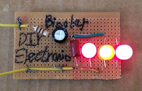
02/16/2021 at 03:59 • 0 commentsThis is a simple frequency light controller:
![]()
Video:
Blinking video:
The bipolar capacitor significantly increases the cost of this circuit. Thus you might try using Schottky or typical silicon diodes used in those links:
https://www.instructables.com/Oscillator-LED-Dimmer-1/
https://hackaday.io/page/9679-oscillator-led-dimmer
Step 1: Design the Circuit
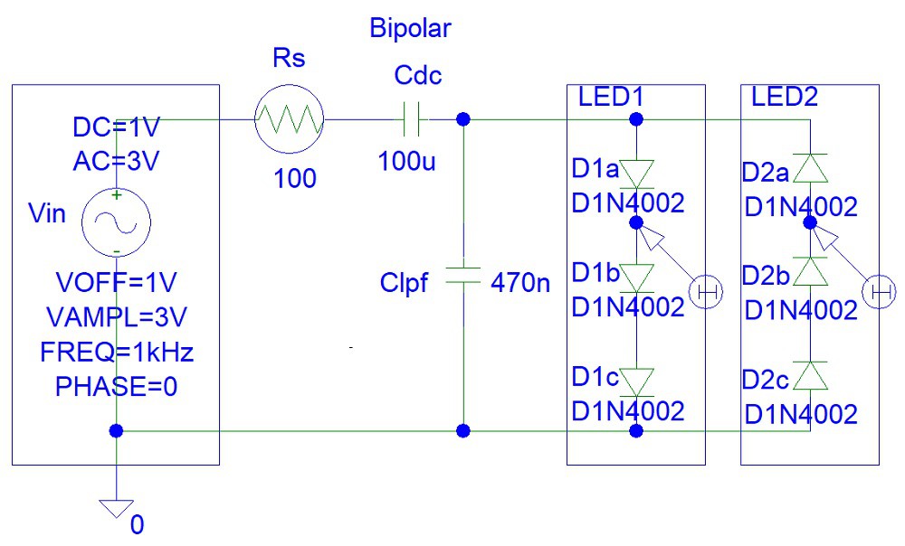
I used an old Student Edition of PSpice simulation software to quickly draw the circuit:
![]()
Keep in mind that my circuit does include high voltage protection. Thus you might easily burn your LEDs.
The 100 uF bipolar capacitor is used to remove the DC component of input signal.
At frequencies above 1 kHz the reactance of the 100 uF bipolar capacitor is almost zero:
Xdc = 1 / (2*pi*1000 Hz*(100*10^-6))
= 1.59154943 ohms
The the maximum low pass frequency will equal to:
fl = 1 / (2*pi*(Rs||Rled)*Clpf)
= 1 / (2*pi*(Rs*Rled/(Rs+Rled))*Clpf)
(Where: Rled = Internal resistance of the LED diode (ohms))
Step 2: Simulations
Simulations show that the two LEDs indicate the direction of the current entering the circuit. The two LEDs are never ON at the same time.
![]()
You can see how the average LED current eventually settles to zero after about 70 ms. You can reduce the settling time to just 7 ms by reducing the Cdc capacitor value. However, then the LEDs will not be ON at low frequencies.
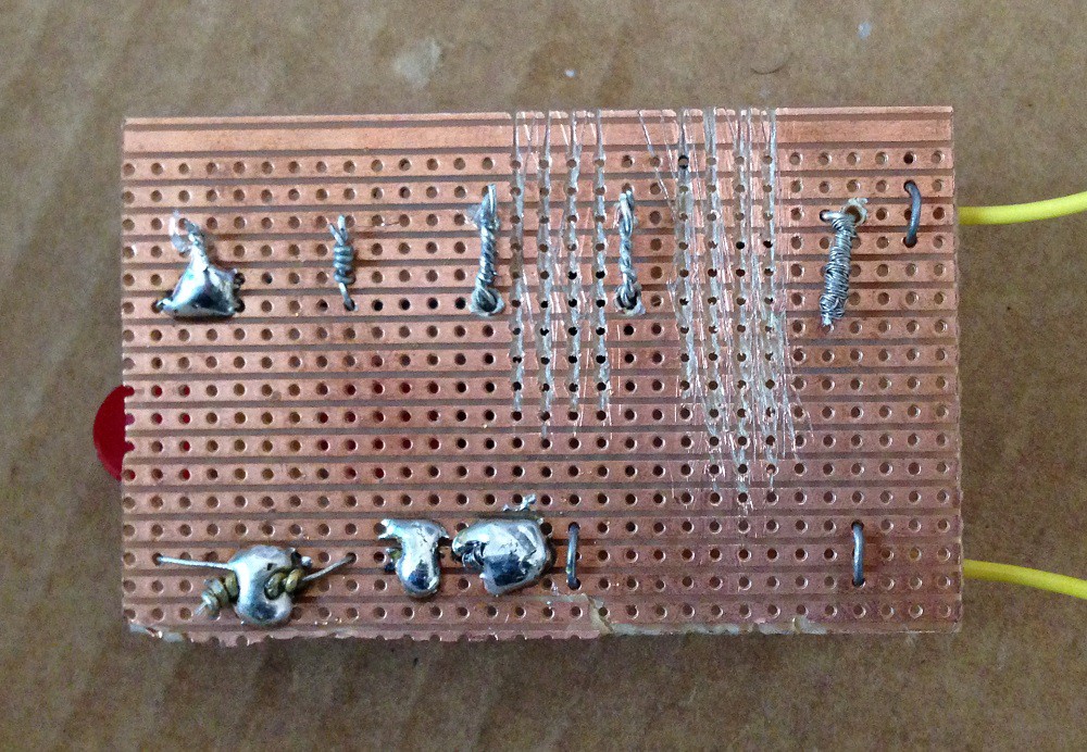
Step 3: Make the Circuit
I used a soldering iron because I modified the circuit a few times, replacing the 10 uF bipolar capacitor with 470 nF pillow capacitor:
![]()
I used the following Veroboard.
![]()
However, you should try using a matrix board instead where each hole is separate.
Step 4: Testing
Further testing was done with pulse width modulation (PWM) waves inputs:
-
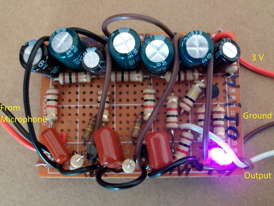
Transistor Microphone Amplifier
08/27/2020 at 09:48 • 0 commentsI made the following transistor microphone amplifier circuit:
![]()
I modified the circuit shown in this link:
https://www.instructables.com/id/Transistor-Microphone-Amplifier/
You can see my circuit working in this video:
You can see hear Nova's voice in this video promoting Renewable Energy Society events. This website is a project sponsored by the Hobby Community organisation.
Step 1: Design the Circuit
I changed the circuit by reducing the values of the collector resistors and thus reducing the cost:
![]()
You only need 1 kohm resistors (not 10 kohm and 1 kohm) and save money by buying in bulk. However, this change increases the transistor power dissipation and will affect the microphone AC signal gain.
I also used a feedback bias instead of a fixed bias to reduce the affect of temperature change on transistor biasing voltages. This change also reduced the circuit gain.
Step 2: Simulations
Transient:
![]()
The maximum current is below 10 mA. However, testing showed that the LEDs could still produce bright light.
Frequency:
![]()
A typical transistor circuit will not have such long bandwidth unless you are using radio frequency transistors.
Step 3: Make the Circuit
I did not have three NPN transistors. Thus I used a PNP transistor for the LED indicator. I had to flip the indicator circuit upside down:
![]()
I used smaller LEDs that might have a maximum current of only 5 mA, not 10 mA that was used in the Instructables link:
https://www.instructables.com/id/Transistor-Microphone-Amplifier/
Step 4: Testing
I connected the circuit to USB oscilloscope:
![]()
You can see that the average Vl voltage is 2.44 V and not 0 V because I flipped the transistor indicator circuit.


 f4hdk
f4hdk Maarten Janssen
 Brian Brocken
 Hexastorm
 Tom Van den Bon
 Daniel
 mwahid
 0miker0
 barb
barb Andrey Skvortsov
 Ken Yap
 w4ilun
 kender.arg
 Mathias Sundgren
 hannah.mishin
 Sherveen Shokoohi