 Enki
Enki-
Megacell Charger HTTP API
09/18/2021 at 18:55 • 0 commentsTable of Contents
1 Introduction
This page gathers independent information about the Megacell Charger focusing primarily on the communications protocol used between the Megacell Monitor and the Megacell Charger with the purpose of creating custom automation.
2 Hardware
The Megacell charger is a 16-slot 18650 litihium ion cell charger with some automation capabilities and software control via 802.11 WLAN. The charger is bundled with software which implements features useful for larger-scale lithium-ion cell refurbishment and reuse. The charger is built around an ESP8266 module which seems to be running NodeMCU.
3 Software
The charger is bundled with a software package called Megacell Monitor which allows for a degree of remote control, setup and automation of the charger. It can also store the cell information in an SQL database, print labels or calculate pack layouts based on the cells inside it's database.
4 The protocol
The protocol is based on HTTP, the charger has to be connected to a 802.11 WLAN network and obtains it's IP address using DHCP. The following requests are understood by the charger (assuming 10.10.10.30 is the charger IP address):
4.1 Charger presence detection and API version
$ curl -i -X POST http://10.10.10.30/api/who_am_i
HTTP/1.1 200 OK
Content-Type: text/json
Content-Length: 35
Connection: close

{  "McC": "Firmware V4.3.0.11"
}
This request is used to scan an IP subnet to detect the presence of chargers which are online. It also allows to obtain the firmware version which might be used to activate firmware-specific features and improve compatibility.
4.2 API v0
As the charger API has no explicit version code, the current API observed to be implemented in firmware version V4.3.0.11 has been designated as v0.
4.2.1 Get charger configuration
$ curl -X POST http://10.10.10.30/api/get_config_info
{  "MaV": 4.2,  "StV": 3.7,  "MiV": 3,  "DiR": 1000,  "MaT": 40,  "DiC": 1,  "FwV": "Firmware V4.3.0.11",  "FirmwareVersion": "Firmware V4.3.0.11",  "ChC": false,  "LmV": 0.3,  "LcV": 3.6,  "LmD": 1.1,  "LmR": 90,  "McH": 240,  "LcR": 1000,  "CcO": 1,  "DcO": 1,  "MsR": 250,  "MuL": 0
}
The parameters here are set in the "Settings" menu of Megacell Monitor UI in two different windows - "Charger Settings" and "Circuit Breaker". They meaning of particular codes is as follows. For some parameters the minimum and maximum values permitted by the UI have been documented. It is not known whether these limits reflect limitations of the hardware or firmware in the Megacell Charger or whether they are what the developers considered "sensible".
Read more »Parameter code Name in Megacell Monitor UI (in Settings) Default value in Megacell Monitor UI Value restriction in Megacell Monitor UI Notes MaV Charger Settings -> Max Voltage (V) 4.2 StV Charger Settings -> Store Voltage (V) 3.7 MiV Charger Settings -> Min Voltage (V) 3 DiR Charger Settings -> Max Discharge (mAh) (sic!) 1000 MaT Charger Settings -> Max Temp (C) 40 DiC Charger Settings -> Discharge Cycles 1 FwV Charger Settings -> Firmware version Cannot be changed in UI ChC Not presented in UI directly A global "busy" flag for the charger: - true when charging/discharging on any slot - false when charger is idle LmV Circuit Breaker -> LVC Minimum voltage (V) 0.3 min 0.01, max 3.0 LcV Circuit Breaker -> LVC charge voltage (V) 3 LmD Circuit Breaker -> LVC Max voltage drop (V) 1.1 LmR Circuit Breaker -> LVC Max trickle... -
Netgear ReadyNAS RN3138
08/13/2021 at 22:22 • 0 commentsTable of Contents
1 Hardware
The Netgear ReadyNAS 3138 is a 1U rack-mounted NAS server with 4 3.5'' SATA drive slots. I have recently purchased such a device in order to use it as a small home fileserver and decided to play with it a small bit before placing it in production use on the network. The manufacturer part number on the sticker that I got was RN31843E which indicates, that the NAS was originally sold with 4 x 3TB disks inside (https://www.cdw.com/product/NETGEAR-ReadyNAS-Rackmount-4x3TB-Enterprise-Drives-RN31843E/3921155). I got it empty however so it's just a plain RN3138.
2 The serial console
The NAS has a standard set of ports with one exception - a 4 PIN 2mm pitch pin header marked "P" on the back which was initially blocked by a sticker. This is the serial console for the NAS which allows you to access stuff not normally reachable via the standard administration mechanisms such as the BIOS or direct Linux console access (including access in the highly privileged "tech support" mode). The console pinout has been described on the Internet already:
- https://blog.rebootr.nl/serial-connection-readynas-102/
- https://gist.github.com/davewongillies/6481138
My NAS had identical pinout, only the connector was "upside down". See photo below:
![thumb-P-connector.jpg]()
When connecting a USB-Serial interface you just need to keep in mind that the arrow points to pin 1 which is always TXD. Also, the serial port voltage levels are 3.3V TTL so you need to pay attention that your interface is 3.3V. Below I have provided a number of dumps of serial port traffic when the NAS is performing different operations. The garbage seen is mostly due to the fact, that the NAS seems to be sending a lot of terminal escape sequences + my serial connection might be a bit flakey:
Normal boot with disks inserted:
Version 2.16.1243. Copyright (C) 2013 American Megatrends, Knc.   $             BIOS Date: 03/05/2015 11:38:52 Ver: ReadyNAS 3130 V0.9                          Press <DEL> or <ESC> to enter setup.                           !                               03 20150820 Copyright (C) !              1994-2014 H.                Peter Anvin                et                al                   "     0      `      $                                                                               �                  !                                                                                                                  �                 "           �                                       "                                 0                     $           "                                                                                                                                                                                           o               k     Loadyng i�itrd.gz.�.                                                                                                                     ( (                                                                                       !   "                                                                                                     !         �                                                                       ok                                                                                                                                  [    3.981708] ismt_smbus 0000:00:13.0: completion wait timed out
[ 0  4.987706] ismt_smbus 0000:00:13.0: completion wait timed out
[    5.993688] ismt_smbus 0000:00:13.0: completion wait timed out
[    6.999691] ismt_smbus 0000:00:13.0: completion wait timed out

Starting the boot process...
Detected system type: RN3130
Loading kernel modules...done
Boot mode: Normal
searching for boot flash..found(sdb)...Bringing up network...done
Bringing up RAID arrays...done
Switching root to RAYD device.
Starting the boot process...
Detected system type: RN3130
Loading kernel modules...done
Boot mode: Normal
searching for boot flash..found(sdb)...Bringing up network...done
Bringing up RAID arrays...done
Switching root to RAYD device.


Welcome to ReadyNASOS 6.9.1!
� [  OK  ] Set up automount Arbitrary Executab...ats File System Automount Point.
[  OK  ] Created slice System Slice.
[  OK  ] Reached target Encrypted Volumes.
[  OK  ] Started Dispatch Password Requests to Console Directory Watch.
[  OK  ] Listening on /dev/initctl Compatibility Named Pipe.
[  OK  ] Listening on Journal Socket.
[  OK  ] Listening on udev Kernel Socket.
[  OK  [[0m] Listening on Journal Socket (/dev/log).                                                             Starting Journal Service...
[  OK  ] Created slice system-serial\x2dgetty.slice.
[  OK  ] Started ReadyNAS LCD splasher.
[  OK  ] Created slice system-getty.slice.
[  OK  ] Reached target Remote File Systems (Pre).         Mounting Debug File System...
[  OK  ] Started Forward Password Requests to Wall Directory Watch.
[  OK  ] Seacled target Remote File Systems.         Staruing Load Kernel$Modules...         [tarting Remount Root and Kernel File Systems...         Mounting POSIX Message Queue File System...
[  OK  ] Reached target Paths.
[ !OK  ] Created slice User and Session Slice.
[  OK  ] Reached target Slices.         Starting ReafyNASOS!system prep...
[ OK ] Listening on udev Control...
Read more » -
IBOX FMT2BT Car FM transmitter
04/13/2021 at 11:40 • 0 commentsIBOX FMT2BT Car FM transmitter
Table of Contents
1 The device
This is a "cup-shaped" car FM transmitter that supports:
- bluetooth speakerphone
- MP3 playback from microsd
- MP3 playback from USB sticks
It's OEM'd by IBOX (https://www.ibox.pl/akcesoria-samochodowe/2050-fmt2.html) and available in many electronics stores in Poland.
![thumb-device.jpg]()
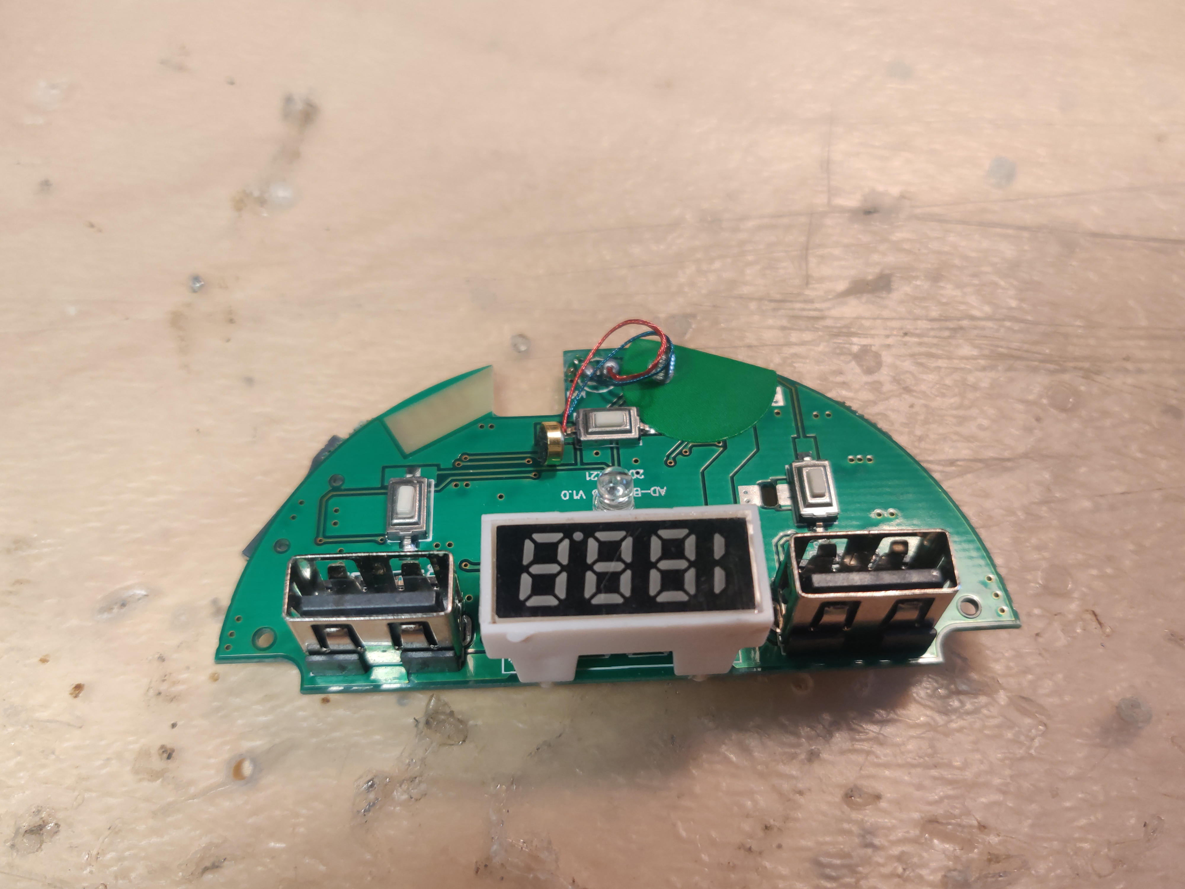
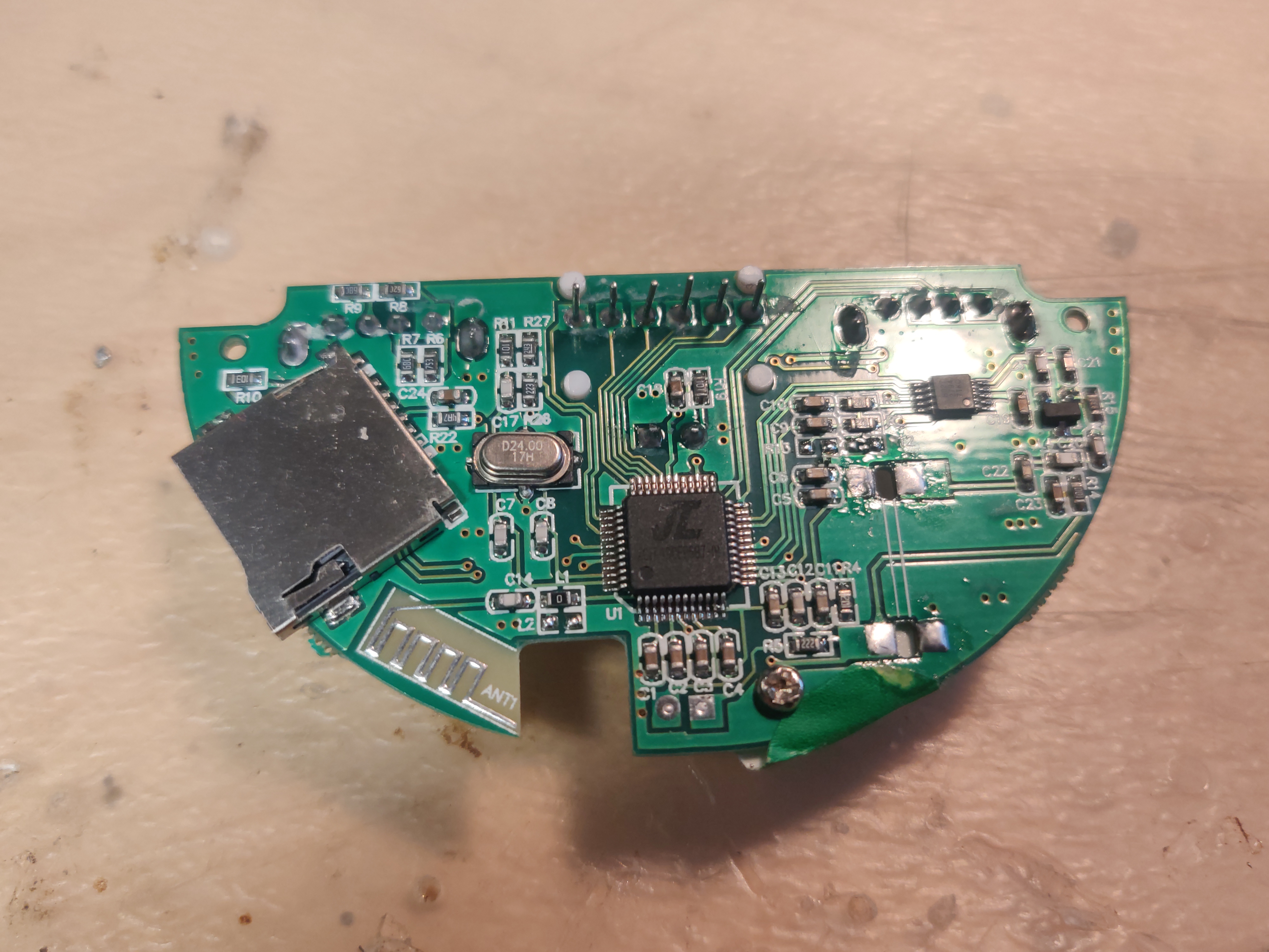
2 The internals
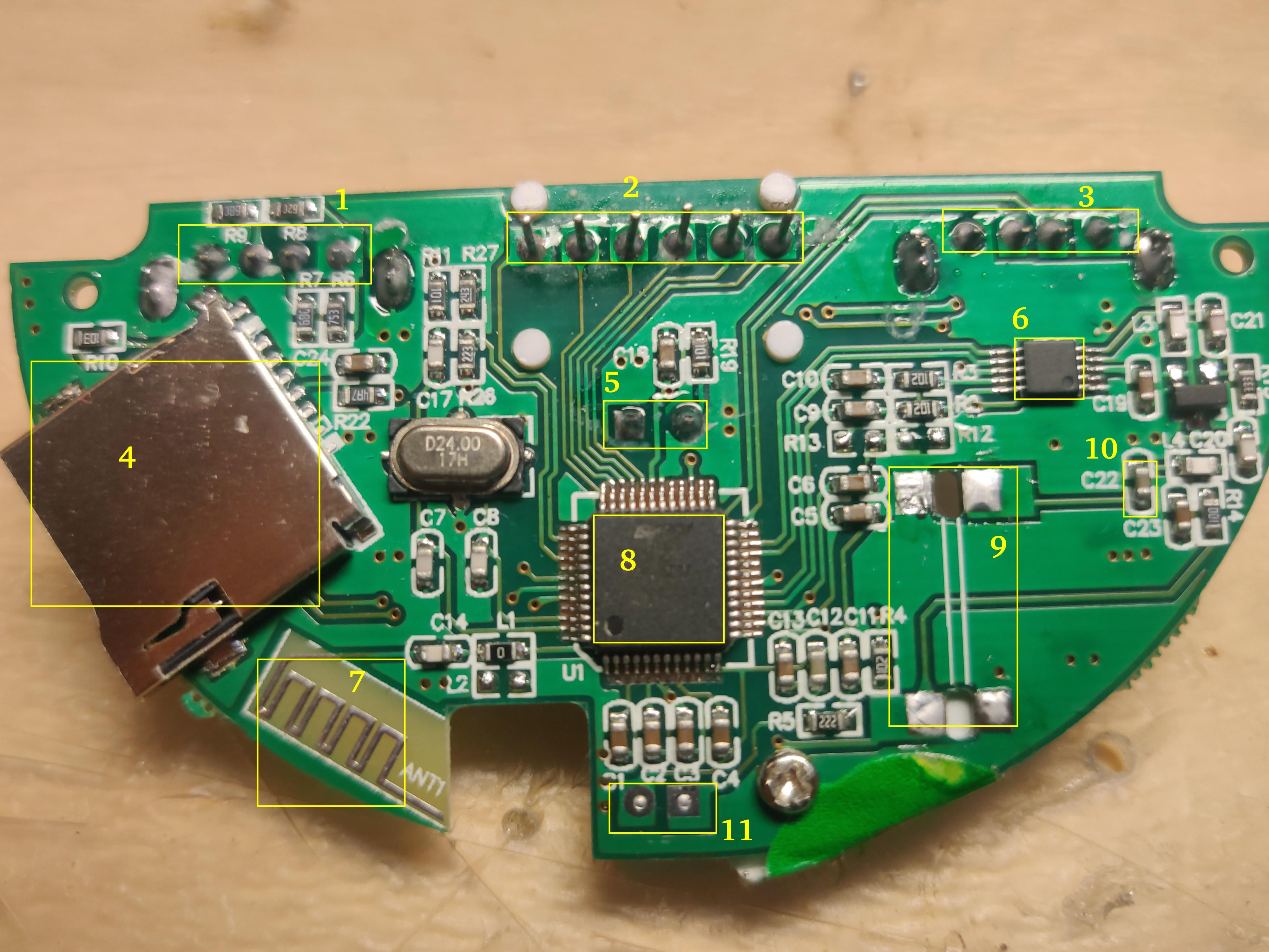
The internals consist of only 1 PCB with all of the connectors and buttons. There is a vertically mounted 5 V power supply which has been unsoldered to make better view of the board. The board has "AD-BT-A23 V1.0" and "2016.11.21" silkscreened on it. The PCB photos with all of the important parts highlighted:
![thumb-pcb1.jpg]()
![thumb-pcb2.jpg]()
![thumb-pcb3.jpg]()
Designation Label Description Type Datasheet Notes 1 5V/2.1A External power output USB-A connector 2 7-segment 3.5 digit display Transmit frequency 3 PLAY USB stick for MP3 playback USB-A connector 4 Micro-SD card slot 5 LED9 Status LED 6 FM trasnmitter QN8027 http://down.cosou.com/xintechsz.com/QN8027.pdf (mirror) 7 Bluetooth Antenna Can transmit RDS 8 U1 Main SoC JL AC1749DEP587-01 LQFP-48, ZhuHai JieLi (珠海杰理) 9 Power supply input (unsoldered) 10 C22 RF coupling capacitor 11 Microphone connector I was unable to find any information about the particular SoC when searching for the exact mark on it. This is likely because JieLi makes a number of chip "families" marketed towards different products and then makes a unique label on each chip based on the exact customer/product it's supposed to go.
By looking at their site I figured that for my device the closest one should be the Jerry Bluetooth series chip AC690N/AC692N.
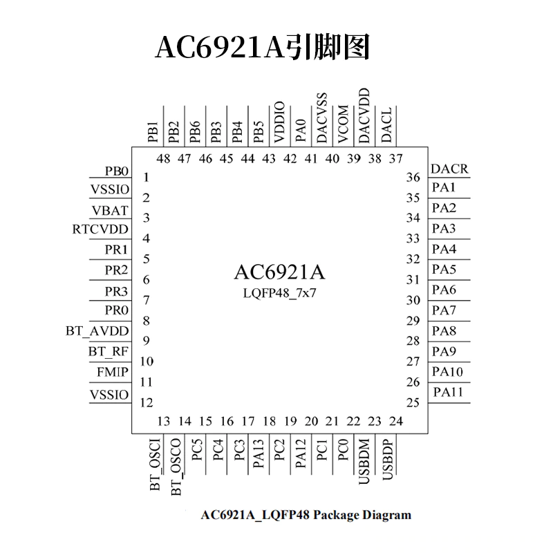
I found some AC6921A chips on aliexpress http://aliexpress.com/i/4001141547298.html which had the same case and a pinout diagram in the auction:
![AC6921A-pinout.png]()
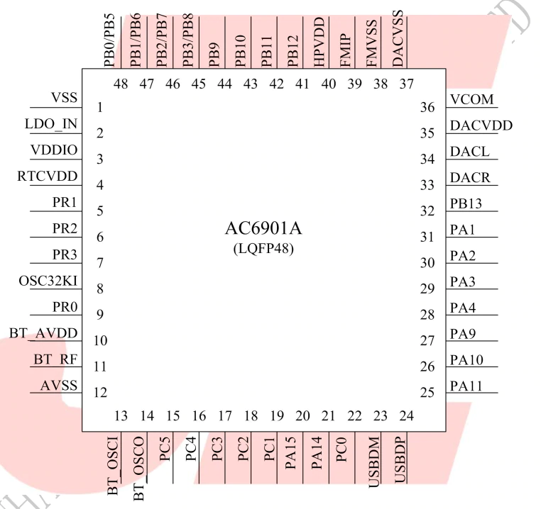
As well as AC6901 chips http://aliexpress.com/i/10000054405573.html with similar pinout diagrams:
![AC6901A-pinout.png]()
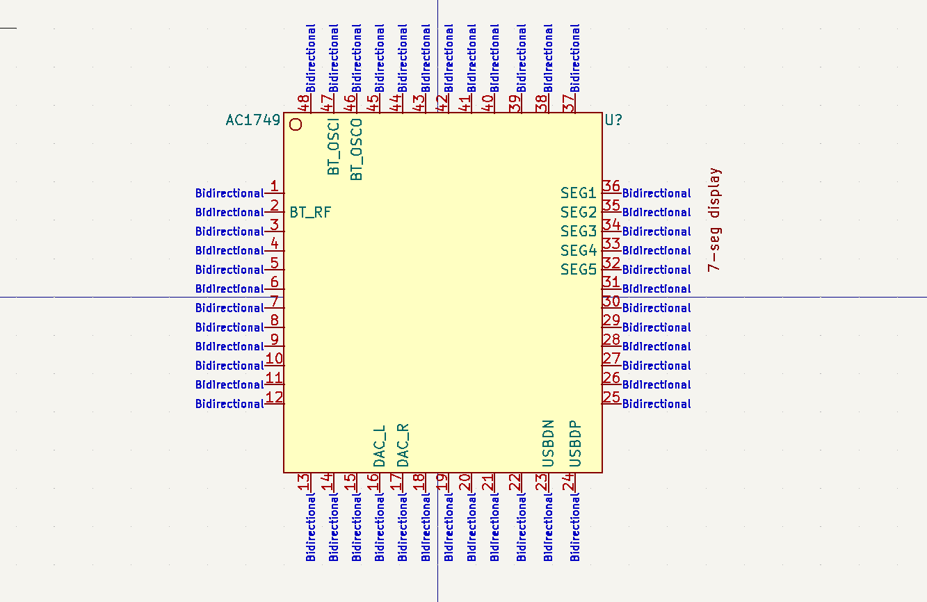
I tried to match both of these chips to what I was seeing on the board but unfortunately none of them match. The pinout that I was able to verify so far:
![AC1749-pinout.png]()
Some other links discovered during research:
https://github.com/christian-kramer/JieLi-AC690X-Familiarization
This is information about the AC690X Bluetooth chip from the same company. This one is different (different package) but things like flashing protocol and so on can be similar.
JL Bluetooth development board chip AC692N series 6925A/6926A/6925B dual mode 5.0 Audio BLE
A development board for the 692X series chips. The development board description provides a convenient link to download an SDK and documentation for the development board: https://drive.google.com/drive/folders/1_rg1CTtwDWYpuCx29A9cRrXnMHIq35l0 (mirror)
JL Development Board Support JL 690X Whole System Jieli Bluetooth Development Board
A development board for the 690X chip, this one unfortunately doesn't come with a SDK download link.
My Projects
My Pages


Projects I Like & Follow
 Arya
Arya Max.K
Max.K yashiro
 Andreas Eriksen
 Open Green Energy
 Stephen Chasey
 Jasper Sikken
 Marc-André Denis
 Andrew Lamchenko
A simple 46mmx22.5mm module to route power and differential signals (RS-485) over RJ-45
 Alexander Williams
 Boris Shabanov
 Neil Lambeth
 Brian Whitsett
 Thane Hunt
 Bud Bennett
 Michael Pick
 Jon
Jon Peter van der Walt
Share this profile
ShareBits

Brian Cornell
wrote 06/28/2021 at 20:07
•
point
Thanks for the like & following https://hackaday.io/project/109068-mosfet-based-solid-state-relays-ssr!

Kris Winer
wrote 06/28/2021 at 15:50
•
point
Thanks for liking my Compact, $25 spectrometer project!

Thomas
wrote 04/18/2021 at 19:36
•
point
Thanks for following my little project - there is certainly some interesting stuff to be found on your side :-)
Thanks for following my #USB to 4 RS232 Ports project!