 danjovic
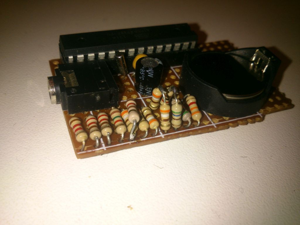
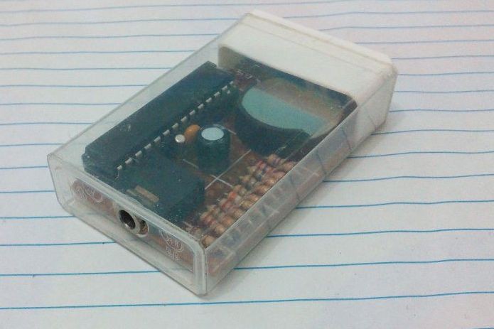
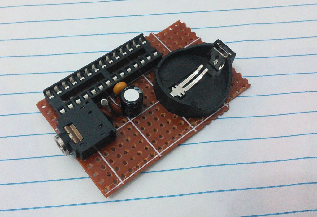
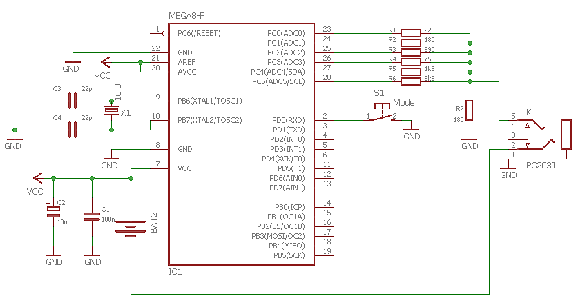
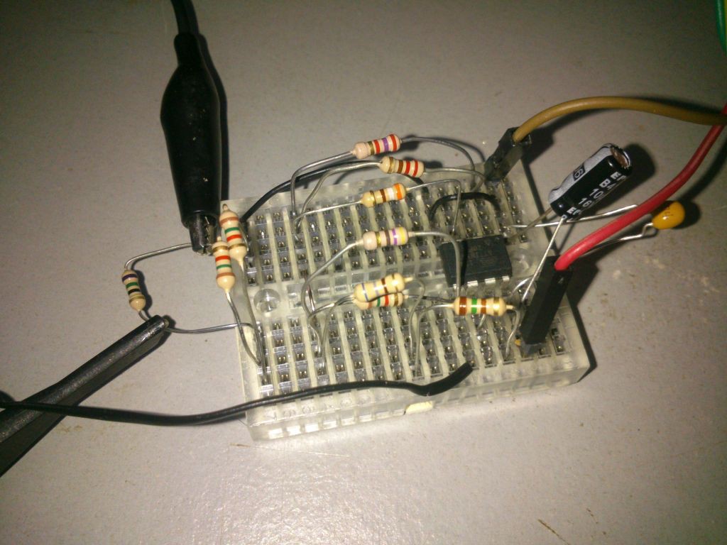
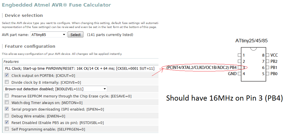
The heart of the project is the ATMegaxx8 ATTiny85 running with internal PLL thus providing 6 pins for generating the video signal, being 5 used for luminance and 1 for synchronism.
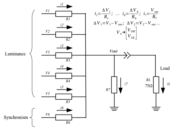
The 5 bits of luminance drive a resistor network that altogether with the pin used for sync are calculated to provide the output voltages expected by RS-170 standard having an output impedance of 75 ohms. To accomplish that some math is required, basically an extension of this article.
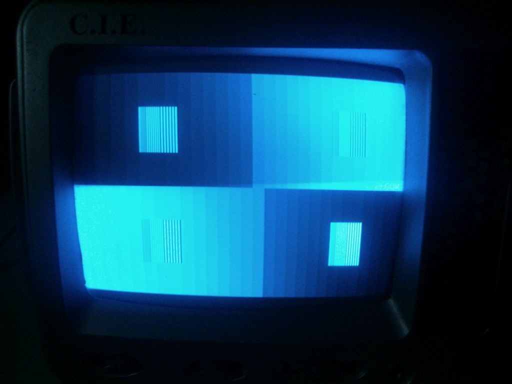
Using 5 bits it is possible to have 32 steps of amplitude from full black to full white, which one will result in one equation. The Sync tip adds another equation, thus giving 33 equations. Such number should be count twice as we need to solve the equations both with and without the 75 ohm load. Then the number of equations is 33 x 2 = 66 equations.
We have 7 terms in each equation, each one corresponds to one of the currents of the circuit above.
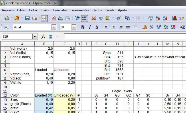
At the end we have a matrix of 66x7 wich might sound frightening but the assembly of such matix can be performed using a spreadsheet program and solely fullfilling some voltage values:
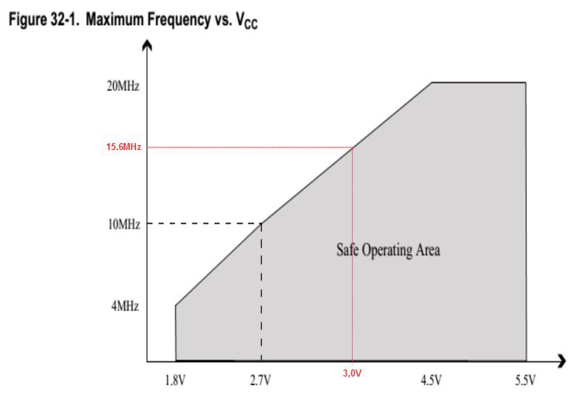
VOH, VOL: Those are the voltage levels for the output signals for a given voltage and both can be found on the datasheet of the microcontroller. For ATTiny85 operating at 3,0Volts such voltages are 2.5V and 0.5V respectively.
VSyncL = DC Voltage level of the sync tip under 75 Ohm load. Should not be zero or negative as the microcontroller is powered by positive voltage only. A value of 0.1V is a good start.
From the values above we can derivate:
VBlackL = The black level under 75 Ohm load should be 0.3 Volts above the voltage of the Sync Tip wich equals 0.4V for a Sync tip level of 0.1V
VWhiteL = The white level under 75 Ohm load should be 0.7 Volts above the black level or 1.1V for the present project.
VSyncO = Sync tip level with Open circuit (no load). Shall be twice the value of the equivalent voltage under load. For this project 0.2V
VBlackO = Black level without load. Same principle, twice the value of the voltage under load or 0.8V for this project.
VWhiteO = Same as above, which means 2.2Volts. Some care must be taken when the source is powered at low voltages as this value can not be higher than the VOH.
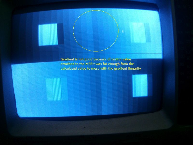
After the calculation (which is explained below) the values obtained were:
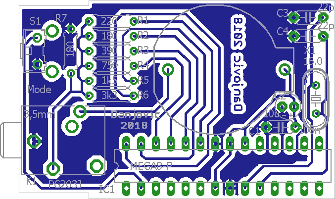
| Resistor | Calculated | Close comercial value |
|---|---|---|
| R1 | 208 | 220 |
| R2 | 412 | 390 |
| R3 | 800 | 820 |
| R4 | 1511 | 1K5 |
| R5 | 2712 | 2K7 |
| R6 | 477 | 470 |
| R7 | 763 | 750 |
As the pin PB5/Reset of the ATTiny85 can't source many current as the other it can be used to drive resistor R5 which will never exceed 925uA (2.5V/2700Ohms)
(Spoiler Alert! Long explanation ahead)
The matrix equation follows Ohm's law:
[ V ] x [ R^-1] = [ I ]
We know the values of [ V ] and [ I ] and we calculate the values of [ R ] by
[ R^-1] = [ V ] ^-1 x [ I ]
and finally [ R ] = 1 / [ R^-1 ]
for simplicity we use the conductance [ R^-1 ] instead of resistance.
The voltage matrix is assembled by spreading the voltage levels from black to white along all the possible bit combinations.
As an example let's see how it is done for 2 bits:
| V1 | V2 | Vout |
|---|---|---|
| VOL | VOL | VBlackL |
| VOL | VOH | VBlackL+ (1/3) (VWhiteL-VBlackL) |
| VOH | VOL | VBlackL+ (2/3) (VWhiteL-VBlackL) |
| VOH | VOH | VWhiteL |
We also have to include the voltage Vsync, which should be kept at high level except at the moment of sync tip. Let's also call the intermediary voltages by a short name to declutter the table.
| V1 | V2 | VSync | Vout should be |
|---|---|---|---|
| VOL | VOL | VOL | VsyncL |
| VOL | VOL | VOH | V0% L |
| VOL | VOH | VOH | V33% L |
| VOH | VOL | VOH | V66% L |
| VOH | VOH | VOH | V100% L |
We use the voltage table above to calculate the Voltage drop over each of the resistors, including the pull down resistor, which has negative value since current sinks throug it (while is sourced by the other)
| Drop R1 | Drop R2 | Drop RSync | Drop R pulldown (-Vout) |
|---|---|---|---|
| VOL-vout | VOL-vout | VOL-vout | -VsyncL |
| VOL-vout | VOL-vout | VOH-vout | -V0% L |
| VOL-vout | VOH-vout | VOH-vout | -V33% L |
| VOH-vout | VOL-vout | VOH-vout | -V66% L |
| VOH-vout | VOH-vout | VOH-vout | -V100% L |
The current...
Read more »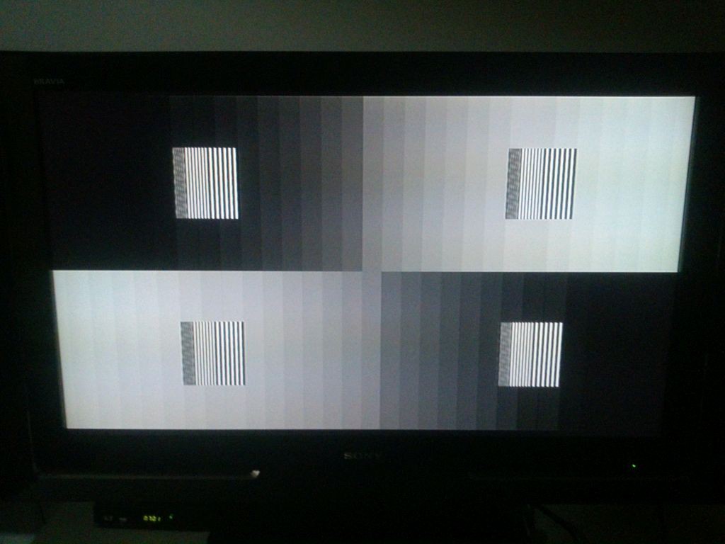


 j
j
 NNNI
NNNI
 Christoph Tack
 sky-guided
Lol thats a punishing specification. You have to do an Open Source one.
'Freed' XD