Close
0%
0%

Sawppy the Rover

Motorized model of Mars rovers Curiosity and Perseverance For Under $500

Similar projects worth following
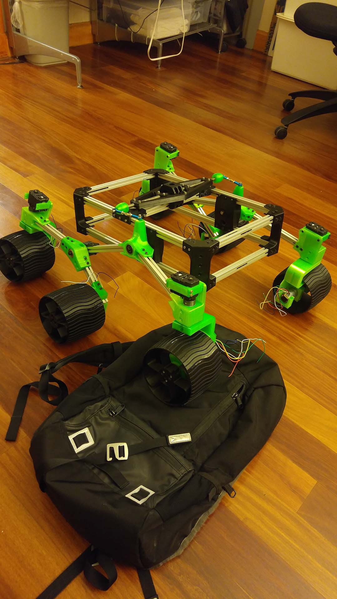
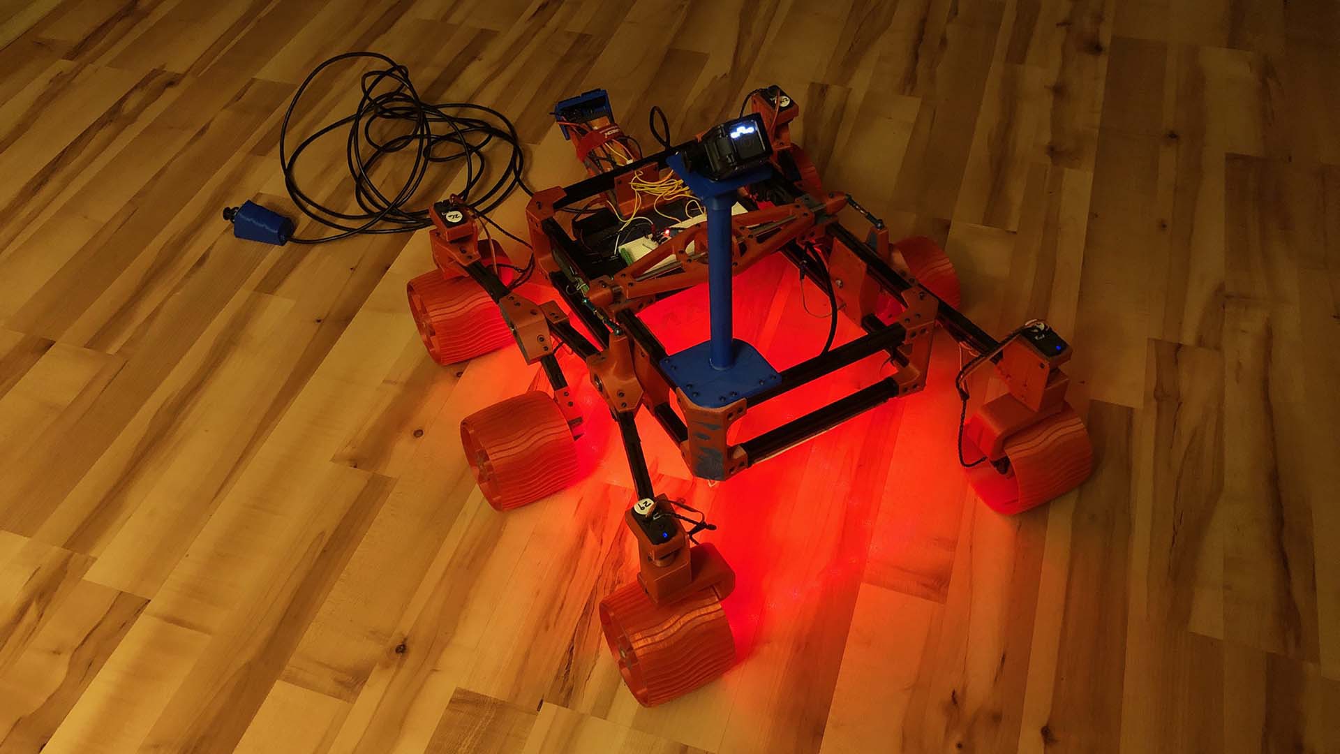
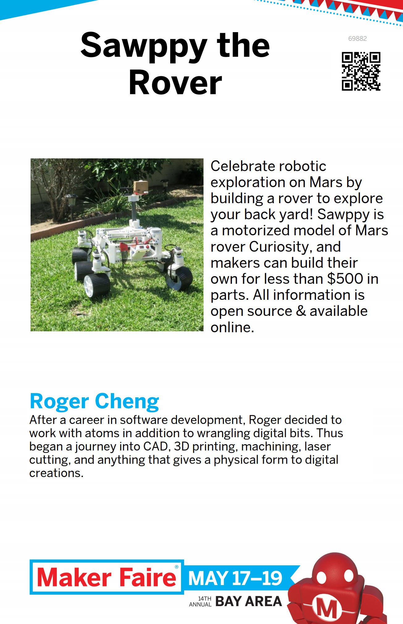
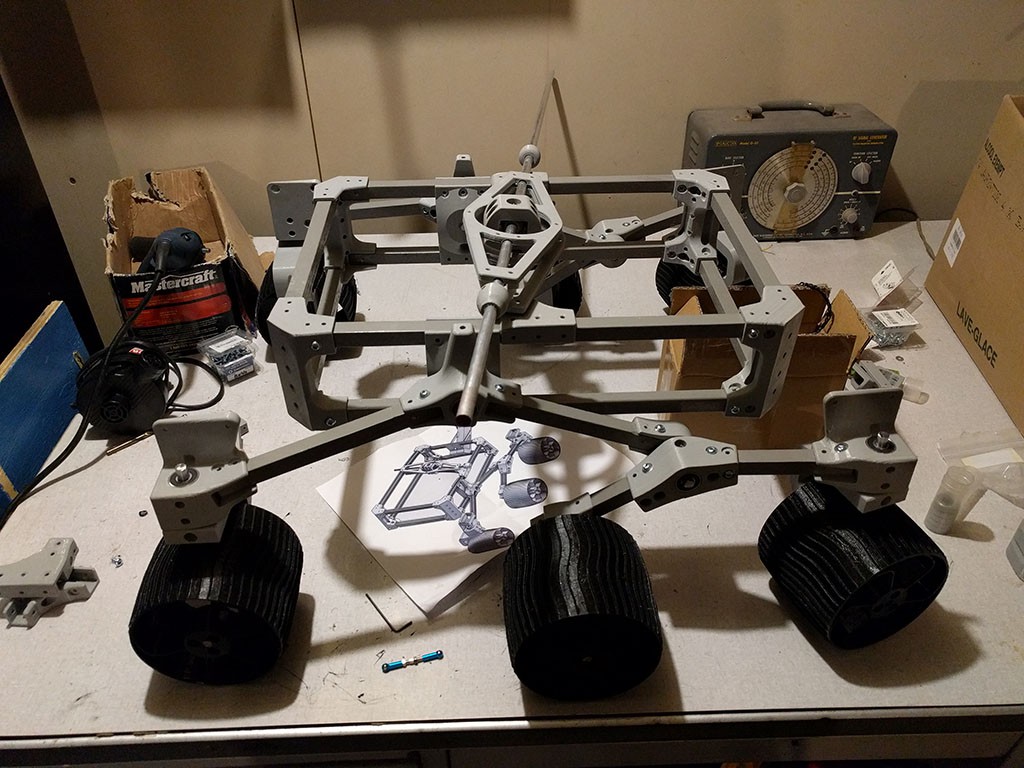
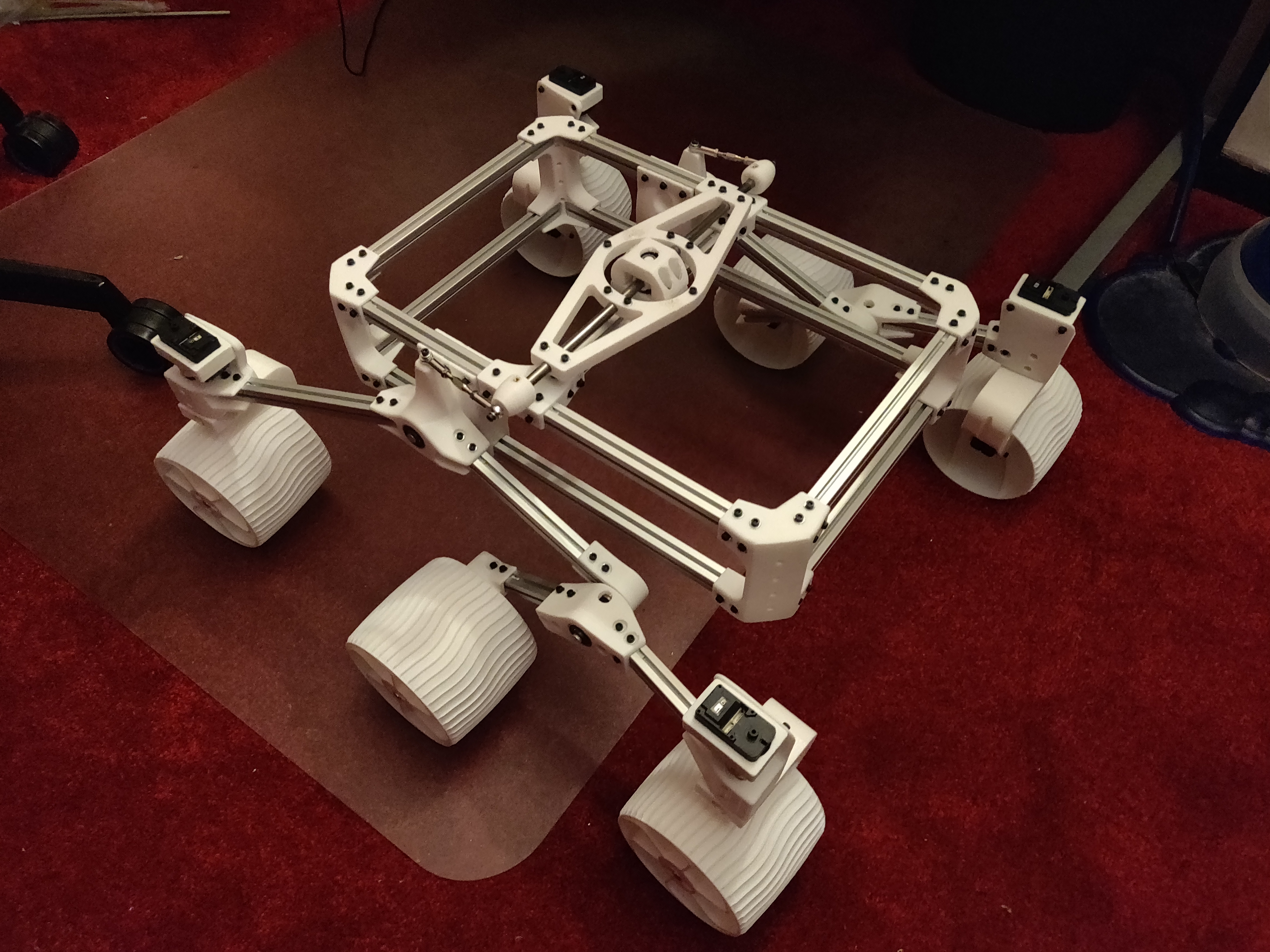
Sawppy is a motorized model whose layout and proportion mimics that of Mars rovers Curiosity and Perseverance. It faithfully reproduces the suspension kinematics of real rovers and is intended to be a hardware platform for future software projects in autonomous operation. Go forth and boldly explore the back yard, Sawppy!

Sawppy the Rover was inspired by JPL's Open Source Rover project. Most of the differences between Sawppy and its JPL inspiration were motivated by a desire to reduce cost and complexity. JPL's rover is designed for education, to be assembled by a school team and give a robust foundation for structured curriculum. Sawppy is more suited for individual hobbyists like myself who are happy to tinker and willing to make some trade-offs to lower cost.

The budget was $500, and getting there required the following changes:

These two major design goals can be summarized as: Servo Actuated Wheels, Printed Interconnect For Extrusion. The acronym SAWPIFE led to the nickname "Sawppy".


See the "Links" section for pointers to additional information:

  • Live Onshape CAD file: This is where I'm tweaking and building Sawppy in full public view. Be warned the live file has upsides (latest ideas!) and downsides (latest idea doesn't work!)
  • Github: This is where the assembly instructions currently live. It also has a snapshot of Sawppy components in STL file format. These parts may lag behind the live CAD data, but they have been printed, installed, and proven to work on my rover.
  • Build Blog: The history of Sawppy, including stories of design goals and lessons learned from failures.

Since the time I declared Sawppy version 1.0 (mechanical foundation) complete and posted assembly instructions, others have built on top of what I've released to the world! They're outlined in the project log "Sawppy Builders" entries, page 1 and page 2 with more to come as I hear about more rovers.

Sawppy V1 Schematic.png

Bare bones Sawppy version 1 schematic

Portable Network Graphics (PNG) - 192.78 kB - 03/13/2019 at 06:14

Preview

  • 3 × 1 kg spool of 3D printer filament Exact amount of filament used will depend on slicer settings, see "Instructions" section.
  • 10 × LewanSoul LX-16A Serial Bus Servo Design also can be adapted to use Dynamixel AX-12A or Herkulex DRS-0101
  • 3 × Box of 100 M3 * 8mm hex bolts Fastening 3D-printed components to aluminum extrusions
  • 3 × Box of 100 M3 hex nuts Fastening 3D-printed components to aluminum extrusions
  • 3 × Box of 100 M3 washers (< 10mm diameter) Fastening 3D-printed components to aluminum extrusions. Design can accommodate up to 10mm diameter washers, larger washers will require modifying CAD file.

View all 17 components

  • 2022/12/15 Hangout and Nerdout

    Roger12/12/2022 at 22:23 0 comments

    "Hangout and Nerdout" will have a space-themed episode on December 15th 2022, and Sawppy will be one of the topics of discussion.

    My presentation slides are here: 20221215 Hangout Nerdout

    Event landing page: https://events.hackster.io/hangoutnerdout

  • Status Update, Perseverance Landing Edition

    Roger03/02/2021 at 02:07 0 comments

    Generating web traffic was never an objective of my Sawppy project so I hadn't kept an eye on the statistics, but I looked at it just now and noticed a distinct rise over the past two weeks. I guess the successful landing of Perseverance rover on Mars motivated a lot of people to think about 3D-printing their own rover here on Earth. Welcome, fellow rover fans!

    Here's a quick summary past and future for fans new and old alike:

    What you see on this project page is what I now refer to as "Sawppy V1". It was my first project that I documented with the explicit goal of helping others build their own. In contrast to most of my other projects which were just to show an example and/or notes to remind myself later. I was happy to see that many people have accepted my invitation and built their own rovers. (See "Sawppy Builders" log entries elsewhere on this page.) I appreciate constructive feedback submitted by Sawppy rover builders from around the world, and have been pondering how I can evolve future Sawppy versions to address feedback.

    One persistent line of feedback was that Sawppy was still too complex and expensive for some rover fans, even though Sawppy was designed to be more affordable and simpler than the JPL Open Source Rover that inspired it. It is true I built Sawppy for myself and others with roughly my level of skill and budget. This translated to an audience of mostly adult hobbyists and some students of college and high school age who can drop $500 USD on a project.

    To address the audience left out of the fun by Sawppy V1, my current step in Sawppy evolution is "Micro Sawppy". I am designing and developing a smaller, simpler, and more affordable rover. One that I want to be accessible to elementary school age students (with adult supervision) with a target parts cost of $100 USD. I also want to write the instructions to be more exact and prescriptive. Sawppy V1 instructions had several areas that were left open to builder preference, something I've learned is confusing to beginners who lacked the experience to have a preference.

    Micro Sawppy also serves as my testbed for several ideas for 3D-printed rover construction that, if successful, I want to adapt and scale up to a "Sawppy V2". This future rover would be roughly the same size as Sawppy V1. But I want to make it easier to build, more adaptable to variations, and a lower base cost target of $400 USD.

    For latest updates and/or more details, I post my development progress to the Sawppy category on my personal blog. (I used to cross-post them to this project page, but I've stopped doing that since it's a different rover project.)

  • Trying to Improve Sawppy Documentation

    Roger11/09/2020 at 07:11 0 comments

    When I decided to release Sawppy to the world, I thought briefly about how to best organize all the information I want to convey for rover assembly. I quickly fell into a state of Analysis Paralysis and, as a path out of that state, decided that it was better to have something written down whatever the format. No matter how unorganized, is still better than keeping it all in my head.

    I first tried putting it in the “Build Instructions” section, but that feature has some strange and unpredictable limitations that became annoying as the length of instructions grew. The final straw was when I noticed that images and instructions for earlier steps were disappearing as I added later steps. That made me… unhappy, so I went to something else.

    The second attempt is what I have as of today: a loose collection of Markdown files on a Github repository. Edited in a code editor rather than a word processor, I struggled with typos and grammatical errors as I lacked the usual automated proofreading tools present in a word processor. Still, with a large helping of assembly pictures, it was just barely enough for people to build their own rovers.

    I was painfully aware of the fact there is a ton of obvious room for improvement. This was just the “get it written down” first stage and at some point I need to revisit the various problems still open. The most significant of which is lack of structure beyond an index page with links to all the other pages. The index suggested a relative ordering that matched my personal assembly order, but that doesn’t necessarily work for anyone else. And worse, they would be stuck if they wanted to ask some specific questions my layout is unable to answer.

    As an example of problems with Sawppy’s documentation, look at a single component: a Sawppy wheel axle. There are at least three entirely separate pages relating to the wheel axle:

    1. The page of parts list, telling a builder to buy 8mm metal shaft.
    2. The page for 8mm shaft modification, where I describe how to cut the long shaft into shorter segments. Followed by steps to turn these segments into wheel axles. Other segments were turned into steering shafts, plus those turned into rocker-bogie suspension pivots.
    3. The page for wheel hub assembly, which incorporates a single segment of the 8mm wheel axle shaft.

    While these three files were all linked from the index page, there’s no obvious way to retrieve the relationship between them in the context of wheel axles. I can manually add links between them, but this is time consuming and perpetually incomplete. Even worse, as the number of relationships grew, it will quickly become a maintenance nightmare.

    Thus I started my quest to find a system to document and track these types of relationships without losing too much of the advantages of my current system. This means every candidate system must meet the following challenges:

    Challenge A: Easy to Contribute

    When a Markdown file is hosted on GitHub, a potential contributor can click the “Edit” button to create a fork of the repository, make a quick fix, and create a pull request all via GitHub website. This presents an extremely low barrier to entry for contributors which is a feature I want to preserve. If contributors were required to install and learn some piece of documentation software, that would discourage many people from participating before we even talk about the learning curve for that software.

    Challenge B: Easy to Manage

    When using GitHub’s web interface to edit a Markdown file, visualizing the change is as simple as clicking over to the “Preview” tab of the editor. Sadly such ease can’t be matched by any system external to GitHub, but it would be nice to have some way to let a contributor see what the end results look like. Failing that, I must have a way to visualize the final impact of changes before I merge a pull request. It is unacceptable to not see changes until after merging into...

    Read more »

  • Rhys Mainwaring’s ROS Melodic Software and Simulator for Sawppy

    Roger01/31/2020 at 22:37 3 comments

    When I created Sawppy, my first goal was to deliver something that could be fun for robotics enthusiasts to play with. The target demographics were high school students and up, which meant creating a software stack that is self-contained and focused enough to be easy to learn and modify.

    To cater to Sawppy builders with ambition for more, one of the future to-do list was to write the necessary modules to drive Sawppy via open source Robot Operating System. (ROS) It is a platform with far more capability, with access to modules created by robotics researchers, but not easy for robotics beginners to pick up. I’ve played with ROS on-and-off since then, never quite reaching the level of proficiency I needed to make it happen.

    So I was very excited to learn of Rhys Mainwaring’s Curio rover. Curio is a Sawppy sibling with largely the same body but running a completely different software stack built on ROS Melodic. Browsing the Curio code repository, I saw far more than just a set of nodes to run a the physical rover, it includes two significant contributions towards a smarter rover.

    Curio Rover in Simulation
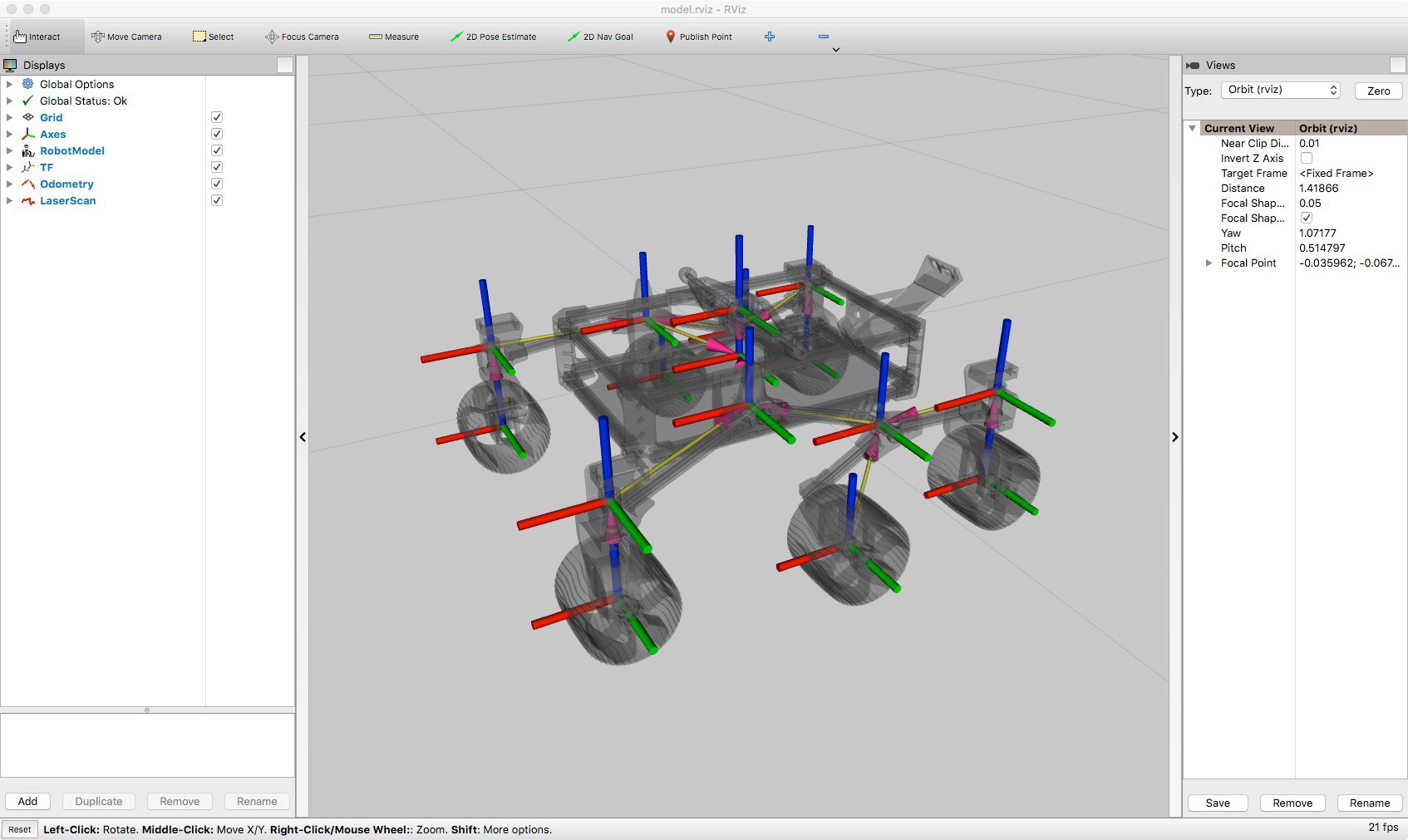
    There’s a common problem with intelligent robotics research today: evolving machine learning algorithms require many iterations and it would take far too long to run them on physical robots. Even more so here because, true to their real-life counterparts, Sawppy and siblings are slow. Rhys has taken Sawppy’s CAD data and translated physical forms and all joint kinematics to the Gazebo robot simulator used by ROS researchers. Now it is possible to work on intelligent rovers in the virtual world before adapting lessons to the real world.

    Rover Odometry
    One of the challenges I recognized (but didn’t know how to solve) was calculating rover wheel odometry. The LX-16A servos used on Sawppy could return wheel position, but only within an approximately 240 degree arc out of the entire 360 degrees circle. Outside of that range, the position data is noisy and unreliable.

    Rhys has managed to overcome this problem with an encoder filter that learned to recognize when the servo position data is unreliable. This forms the basis of a system to calculate odometry that works well with existing hardware and can be even faster with an additional Arduino.

    ROS Software Stack For Sawppy
    Several people have asked me for ROS software for Sawppy, and I’m glad Rhys stepped up to the challenge and contributed this work back to the community. I encourage all the Sawppy builders who wanted ROS to look over Rhys’ work and contribute if it is within your skills to do so. As a ROS beginner myself, I will be alongside you, learning from this project and trying to run it on my own rover.

    https://github.com/srmainwaring/curio


    (Cross-posted to NewScrewdriver.com)

  • Sawppy Builders (Page 2)

    Roger08/23/2019 at 07:48 2 comments

    This is the second page of Sawppy Builders, for Page 1 click here.


    Steve (jetdillo)

    I met Steve at Maker Faire Bay Area 2019 in May, where he showed me pictures of a few of his Sawppy parts. It is now August 2019 and his Sawppy is mechanically complete. Steve is a HomeBrew Robotics member like Marco, and the new rover is neon green to distinguish from Marco's neon yellow Sawppy.

    In terms of modifications, Steve is adopting Marco's faster wheel drive motors, and instead of cutting drive shafts from metal Steve has printed his from NylonX. It'll be interesting to see if that material is strong enough for the job!

    See more details at Steve's YASP (Yet Another Sawppy Project) page.


    Leif Sorgule

    Leif is teaching a robotics course for high school students and he thought Sawppy might be an interesting team project for the class. The class will start with the Arduino control option, given cost and learning resources available for Arduino. It'll be fun to see what the students dream up for their own Sawppy modifications.


    Patrick Leiser

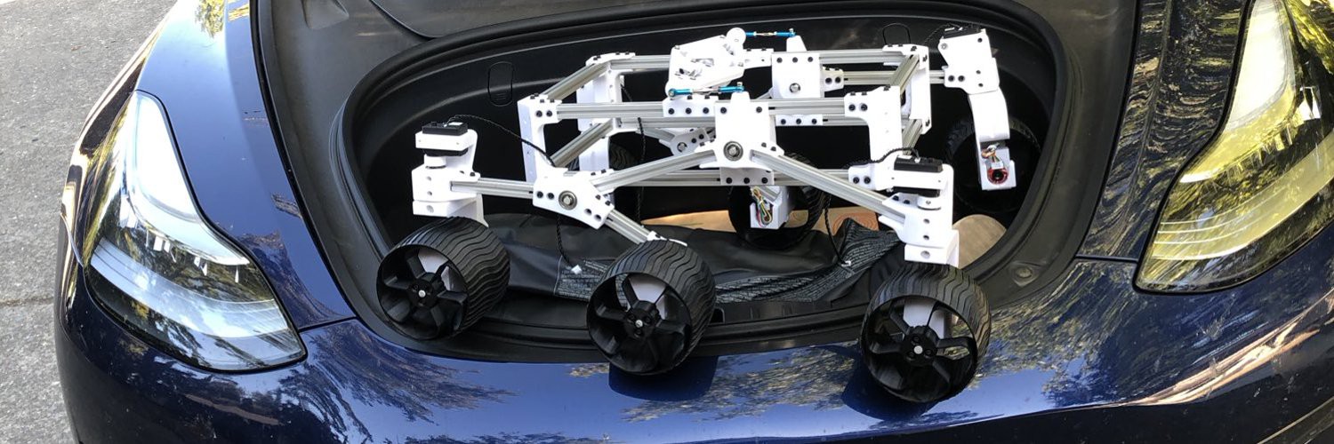
    Patrick's Sawppy variant (named Swappy) made an appearance at the Rocklin Mini Maker Faire, representing the Sierra College Robotics Club. It might be the first of Sawppy's siblings to be chauffeured around in a Tesla Model 3, though this picture shows it doesn't quite fit in the frunk.


    TeamSG Aussie Sawppy

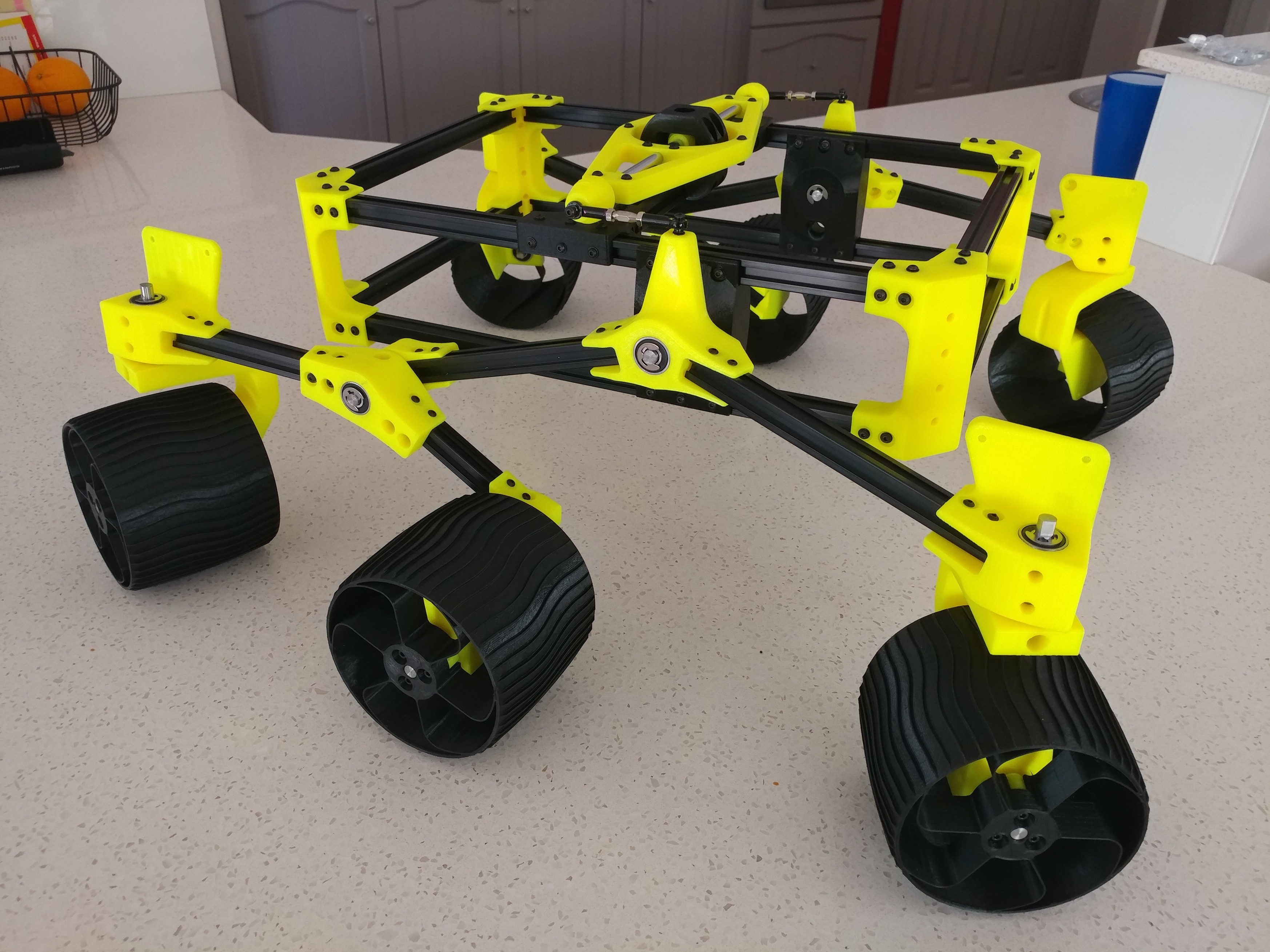
    Sawppy has a brother down under! This is a father-and-son team putting a rover together, and their chosen yellow-and-black color scheme looks very sharp.


    ... and hopefully more rovers to come!

  • Sawppy at Maker Faire Bay Area 2019

    Roger07/28/2019 at 23:53 0 comments

    I took some footage of Sawppy's adventures at Maker Faire Bay Area 2019 and assembled them into three videos.

    It was raining at the event, so Sawppy needed to put on a raincoat before venturing outdoors:

    It was the first time Sawppy attended a three-day long event and one of the steering servos failed on the third day.

    After the event, Sawppy needed some cleaning and minor repairs.

  • Curiosity Rover 3D Resources

    Roger06/25/2019 at 20:52 0 comments

    Prompted by a question on the JPL Open Source Rover web forum, I compiled all the 3D resources I had collected on Mars rover Curiosity. This reference data helped Sawppy match Curiosity's overall proportions and suspension geometry, which was my goal of making a mechanically faithful motorized model. I stopped there, but others rover builders like @lmckeega are working to improve accuracy in appearance so I thought I'd share these resources to assist such efforts.

    3D web sites

    My starting point was JPL's official open source rover website whose opening animation has a 3D model of Curiosity cruising on a simulated Mars surface. I tried to extract that 3D mesh without success.

    On a similar front, we could see a 3D model of Curiosity in the "Experience Curiosity" website. It's possible this is using the exact same data set as the OSR, but still I'm not enough of a web developer to pull out the 3D data.

    Finally we have a 3D model visible on Curiosity's mission site. Again it may or may not be the exact same one used in above two sites, but the difference here is that we have a "Download" button. Clicking that button results in a file named Curiosity_static.glb. My laptop running Windows 10 has a 3D Viewer app installed by default, which was able to view this file. I don't know what viewer software would be required for other platforms.

    3D printing

    A web search for "Curiosity 3D Model" and similar keywords would repeatedly lead me to a 3D-printable static model. Unfortunately, for my purposes this model is not useful. The geometry of this model were modified to be friendly to 3D printing and is not a faithful representation of Curiosity.

    3D animation

    However, on the same site, there are two Curiosity models for the free open source 3D animation program Blender. As far as I can tell, these two models have the same 3D data but with different textures. "Clean" is factory fresh Curiosity, and "Dirty" represents Curiosity after cruising on Mars for a while.

    The advantage of these files is that suspension parts are separate elements that can be animated to show suspension articulation. I believe these files formed the basis for Gazebo simulation described here.

    It also means we can split parts apart for a closer look. However, this file only has enough detail for animated graphics, it does not have enough detail for CNC machining. Much of the surface detail are represented by bitmap textures instead of 3D mesh data.

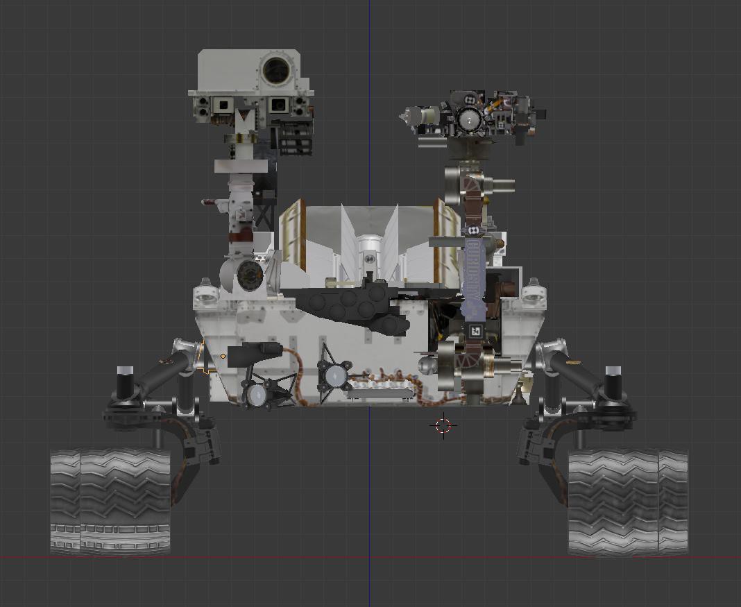
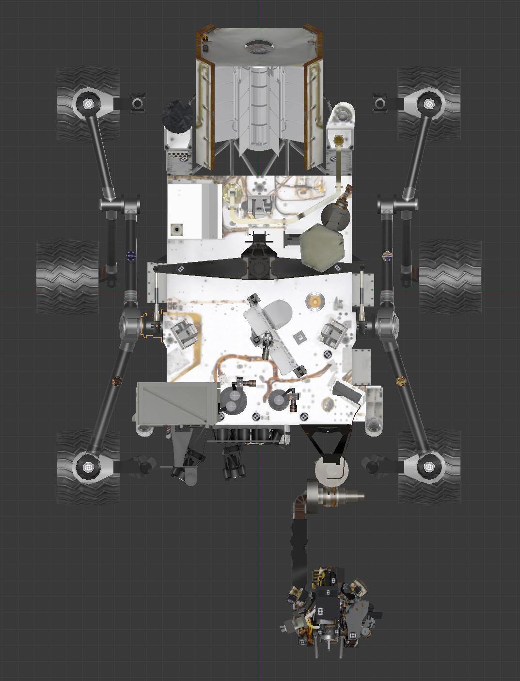
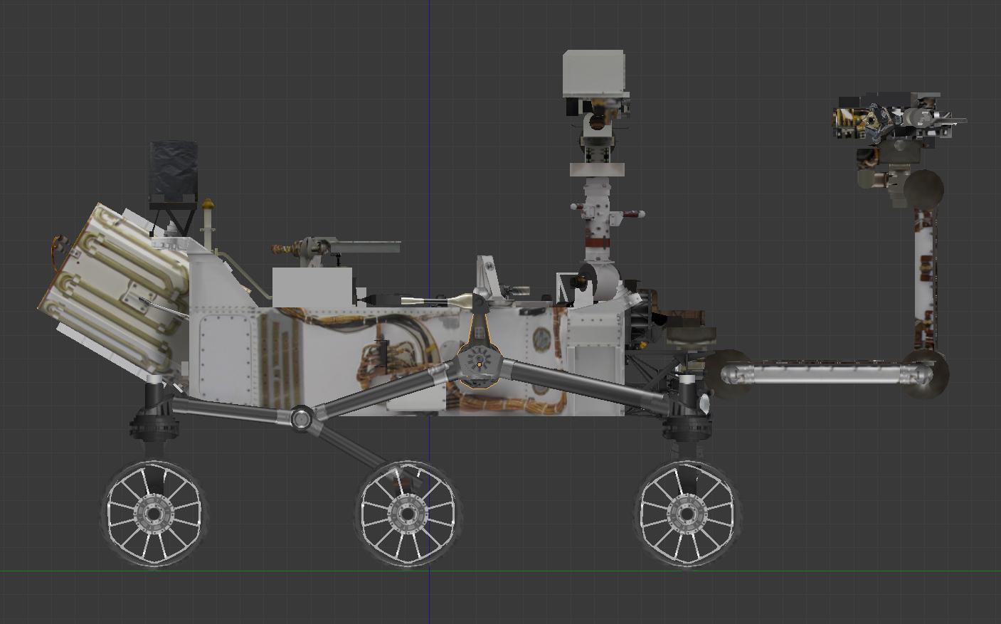
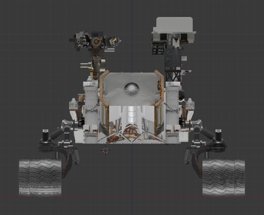
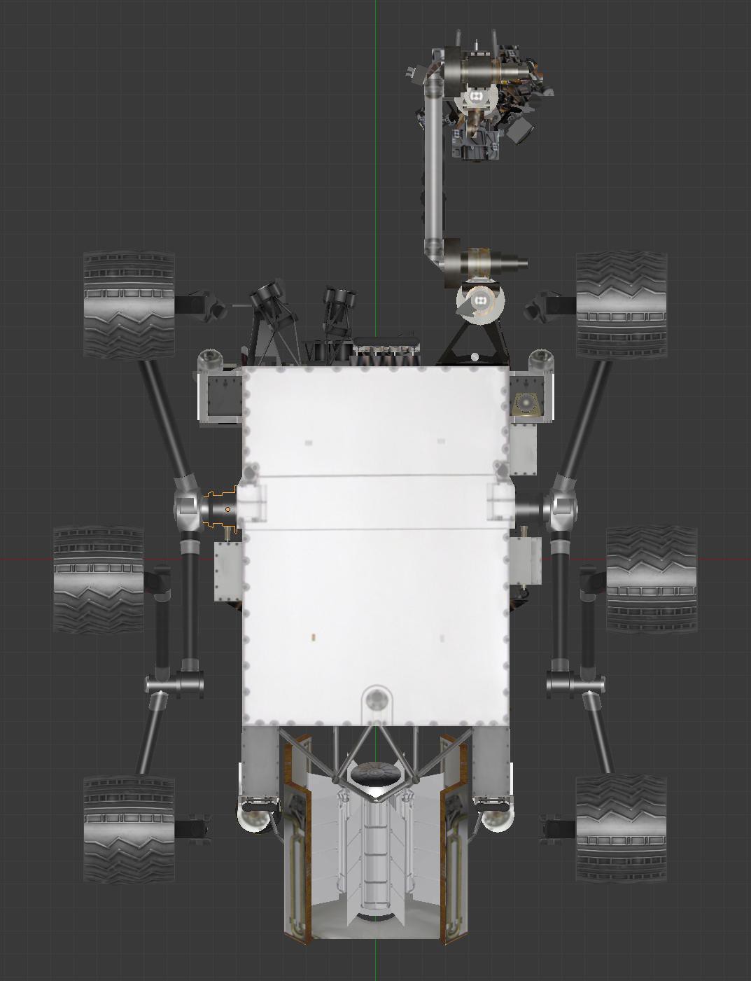
    While there is not enough detail for building a high fidelity model, these files were the best resource I had to measure component sizes and their relative layouts. I was able to bring them up in Blender, switch to orthographic projection view, and get images of Curiosity free of perspective distortion. In case that's useful to anyone, and you don't want to install & run Blender just to obtain those images, here they are:

    (Cross-posted to NewScrewdriver.com)

  • Wired Joystick Controller With Arduino

    Roger05/24/2019 at 00:37 2 comments

    As a presenter it was great to see the wealth of information provided by Maker Faire Bay Area organizers. It is clearly the compilation of many years of experience and lessons learned. One item caught my eye: anyone using wireless communication should have a contingency plan in case wireless fails.

    I've definitely encountered this before with SGVHAK Rover and Sawppy on the standard 2.4GHz WiFi band. So far I've been able to avoid most problems by adding a dual-band router and moving up to the 5 GHz band, but in a large event like the flagship Maker Faire, even that might not be enough.

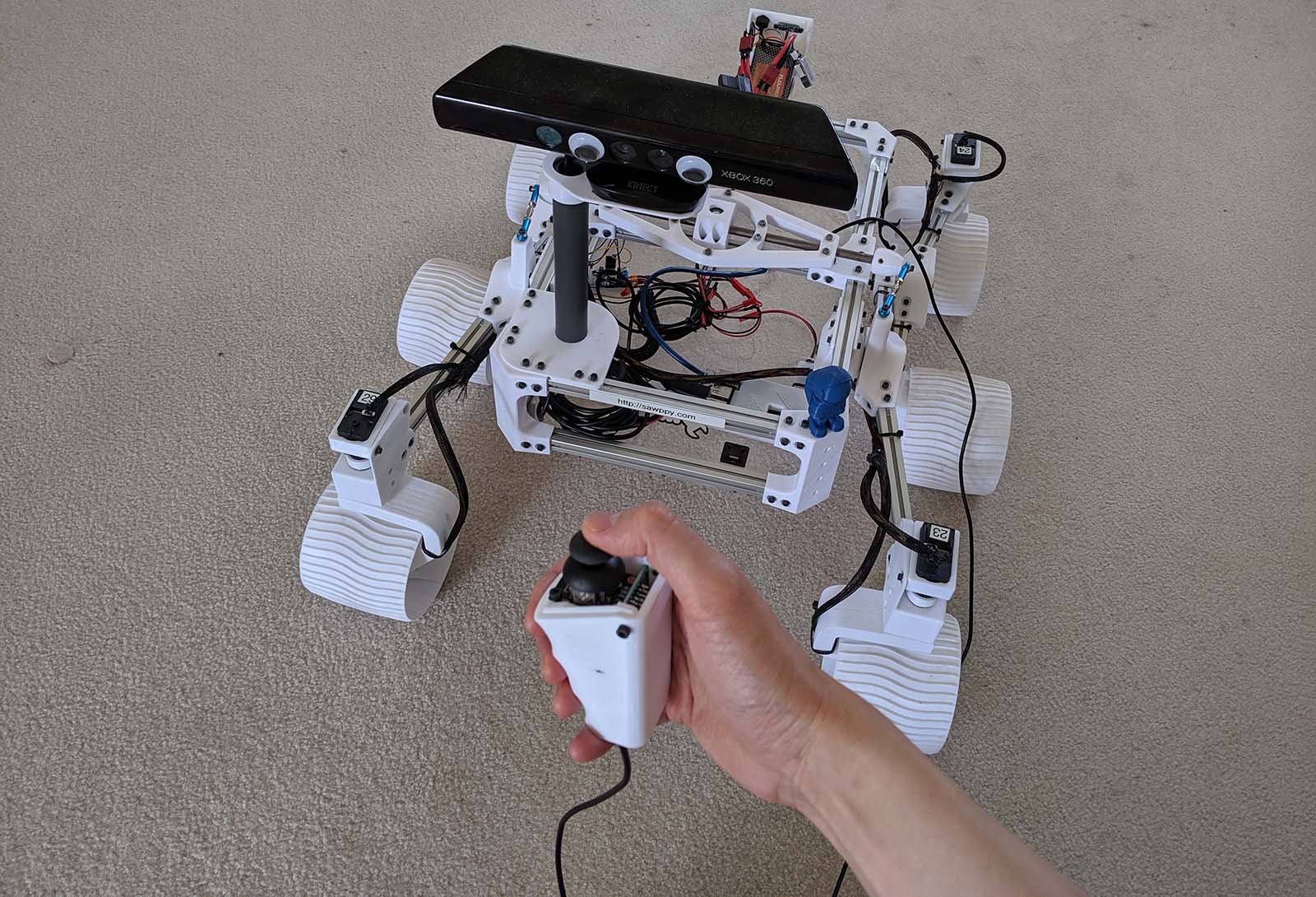
    So as part of my Maker Faire prep work, I designed and built a wired joystick controller with an Arduino as the microprocessor. When active, it replaces the Raspberry Pi and wireless router on board Sawppy. This also serves as a lower-cost alternative to rover builders or those who like the thought of walking their rovers on a leash.

    More resources:

  • Sawppy Will Be At Maker Faire Bay Area 2019

    Roger05/10/2019 at 19:43 0 comments

    I know I've said I wanted to keep my Hackaday.io project page focused on rover design and evolution and less on rover adventures in the wild... but I'm going to break my own rule for this one. I'm super excited to have been accepted as a maker presenting their project at Maker Faire Bay Area 2019. It's not just A maker faire... it is THE maker faire. Most of my travel logistics have been nailed down, it is happening!

  • Sawppy Builders (Page 1)

    Roger05/07/2019 at 23:03 0 comments

    I started my Sawppy project in March 2018. By May 2018 I had my first rolling chassis but it was fragile. Every time my rover broke, I learn a little more about mechanical design, and Sawppy improved over the following months. I also started writing assembly instructions and supporting documentation to help any other interested people build their own Sawppy, not knowing if anyone would take me up on my offer. It was extremely gratifying to see other people have indeed accepted my invitation!

    This post recognizes those who have embarked on their own Sawppy adventures, roughly in the order of when I learned about their efforts. Sometimes I learn about their ambitions before they got started, sometimes I learn about it only after their rover had been completed. Given this, it is likely there are other Sawppy builders out there I don't know about at all! But that's fine, I just love the fact there are more Sawppy rovers running around.

    I used to list a few Sawppy builders in my main project description page, but the list has grown too long to fit in that space. I'm going to track Sawppy builds on this project log entry, editing it as I go to add more rovers as they come online. I don't know if there'll ever be a day when even this is too unwieldy to track all the Sawppy builds out there... but as far as problems go, that's one I would be very happy to have.

    To everyone who decided my project was worth your own time and money and effort to build: Thank you.

    Roger


    Daniel Perron

    Daniel was one of the first to jump in and start exploring the information I had released. Daniel also helped spread the word of Sawppy via comments on various web page comments about JPL's Open Source Rover, and for that I'm grateful.

    I designed Sawppy to use Misumi aluminum extrusions because I saw Misumi had distributors worldwide. Unfortunately my hope of easy availability turned out to be wrong in Canada. But makers are problem solvers! Daniel redesigned his Sawppy to use wooden beams instead.


    Quinn Morley

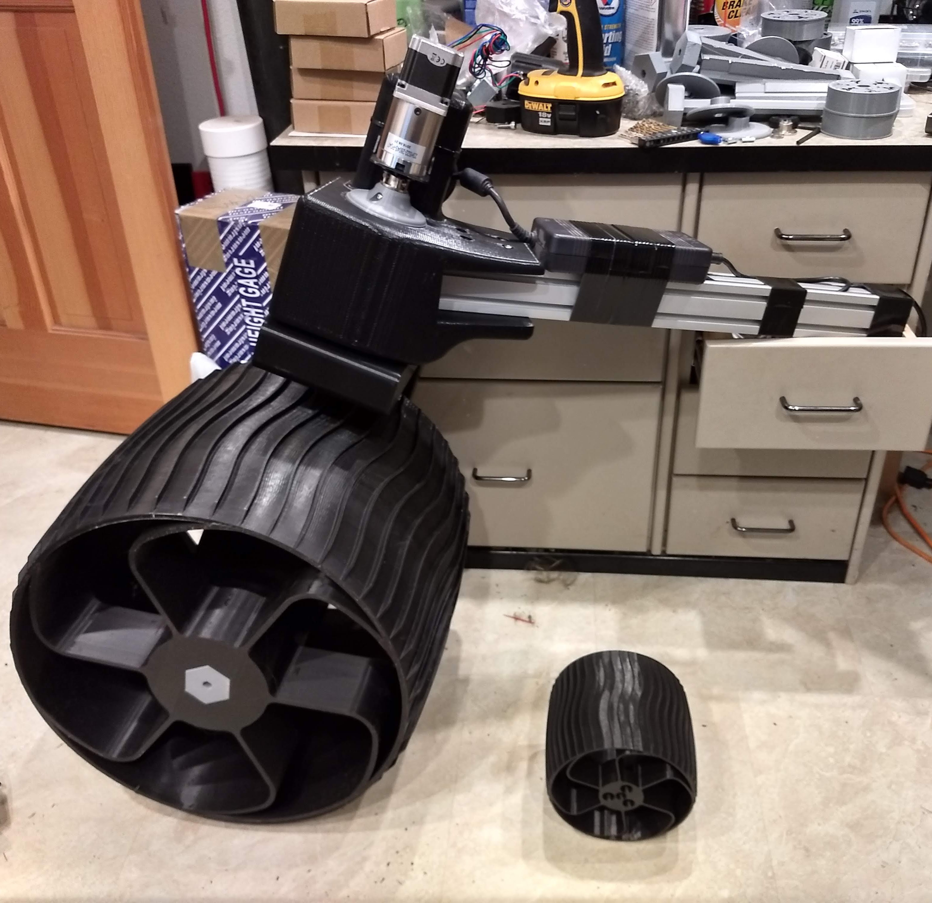
    Quinn is a person who thinks big. Quinn has been working to scale up Sawppy's design, making modifications as needed, for a much larger rover. This picture shows one of his big wheels next to a standard sized Sawppy wheel. This rover will be a mobile testbed for his project developing deep ice drilling techniques.


    Bob Krause, Inventor Studios

    Bob leads a FIRST Robotics team and they have their own version of Sawppy's CAD file filled with their improvements for a better fit with what they want their rover to do. They can't use their rover in an actual FIRST competition because I didn't design Sawppy around competition rules. However, the team members are thinking about using Sawppy's construction technique for their future projects. All of this makes me extremely happy.


    Chris Dakin

    Sawppy has a sibling in the UK! During Sawppy's evolution I had to adjust various pieces and occasionally aluminum extrusion lengths. This resulted in some recuts and some unnecessary (in hindsight) waste. When I documented their final dimensions, I thought it was possible someone could cut all the required pieces out of two extrusion beams at the 2 meter standard length sold by Misumi. Thanks to the build log for Chris' Sawppy, I saw this hypothesis has been proven.


    Marco Walther

    Marco has lots of robot building experience and wanted to add a Sawppy to his robot army. I received many helpful pieces of feedback about my posted instructions for Sawppy, pointing out where I could...

    Read more »

View all 43 project logs

  • 1
    New Home for Sawppy Build Instructions

    After a loss of data event for instructions posted to hackaday.io, Sawppy the Rover's build instructions are now hosted on Github.

View all instructions

Enjoy this project?

Share

Discussions

Ed wrote 07/21/2024 at 02:04 point

Hey Roger, 

I am resuming this project after a few years in the closet. Got all the hardware assembled and started playing with the software but I am stuck on something for a few days already. 

I get this error in both my macbook and the raspberry PI (ubuntu). Both running python 3.12.3 

---

Error: While importing 'SGVHAK_Rover', an ImportError was raised:

Traceback (most recent call last):

  File "/home/maciel/SGVHAK_Rover/venv/lib/python3.12/site-packages/flask/cli.py", line 245, in locate_app

    __import__(module_name)

  File "/home/maciel/SGVHAK_Rover/SGVHAK_Rover/__init__.py", line 32, in <module>

    import SGVHAK_Rover.menu

  File "/home/maciel/SGVHAK_Rover/SGVHAK_Rover/menu.py", line 28, in <module>

    import roverchassis

ModuleNotFoundError: No module named 'roverchassis'


---

I can use lewansoul_wrapper.py to query and set the servos ID, but when I try to start flask I get that. 

Anything that immediately pops in your mind?

Thanks
Ed

  Are you sure? yes | no

Roger wrote 07/21/2024 at 06:56 point

The SGVHAK_Rover project was written on Python 2.7.14 due to a dependency on RoboClaw library. Sawppy doesn't use a RoboClaw controller so it should be possible to port to Python 3 but I have not allocated time to do so.

There may have been a change in module import behavior between Python 2 and 3. I did a web search "module import breaking change python 2 to 3" and looks like yeah there were changes.

  Are you sure? yes | no

Laura C. wrote 04/08/2024 at 02:25 point

Hello! I am building Swappy and it has been great; I've learned a lot. I am having some issues with the software, however. I am using the modified SGVHAK software, as recommended.  Although things were going well until start flask with python 3, at this point I began to have issues, and after consulting a friend, I switched to python 2.7, only to have trouble installing the virtual environment and getting several error messages. I am at a standstill and am not sure how to move forward. Can you recommend a way to proceed? Thank you very much!

  Are you sure? yes | no

Roger wrote 07/21/2024 at 06:51 point
Sorry I didn't see this message until today. I hope you found a way forward on your own. Generally speaking I can't do much to help unless I see an error message.

  Are you sure? yes | no

Ed wrote 09/01/2024 at 19:47 point

Hey Laura, I am also stuck with the python version. 
I installed python 2.7, but when I am installing the dependencies on the virtual environment, I get an error like this:
----------

ERROR: Command errored out with exit status 1:

   command: /home/maciel/SGVHAK_Rover/venv/bin/python /home/maciel/SGVHAK_Rover/venv/lib/python2.7/site-packages/pip install --ignore-installed --no-user --prefix /tmp/pip-build-env-MvUapZ/overlay --no-warn-script-location --no-binary :none: --only-binary :none: -i https://pypi.org/simple -- 'setuptools>=61.0'

`  ERROR: Could not find a version that satisfies the requirement setuptools>=61.0 `

DEPRECATION: Python 2.7 reached the end of its life on January 1st, 2020. Please upgrade your Python as Python 2.7 is no longer maintained. pip 21.0 will drop support for Python 2.7 in January 2021. More details about Python 2 support in pip can be found at https://pip.pypa.io/en/latest/development/release-process/#python-2-support pip 21.0 will remove support for this functionality.

----------

I even tried installing the dependencies one by one, and some succeed, but others will complain about the setuptools version.

I hope you got past this issue. 

  Are you sure? yes | no

Leandro Ebner wrote 03/17/2024 at 00:09 point

would it be possible to scale all STLs by 2 and use 30x30 profiles instead?
I like the size of the JPL OSR and Like to carry payload which seems too much for the 1/4 scaled Curiosity styled Sawppy 

  Are you sure? yes | no

Roger wrote 03/17/2024 at 01:26 point

Possible: definitely! Practical: well... it depends.

In addition to the beams you'd also have to make sure the fasteners are also lined up for double-sized use. I don't know of a nice neat double size servo that'd just bolt in, so you would have to modify the design to accommodate larger motors/servos to handle wheel steering and rolling.

For precedence, here's a project that scales Sawppy by 4. It required modification to use different motors, as well as different beam fasteners: https://hackaday.io/project/165401

  Are you sure? yes | no

Leandro Ebner wrote 03/17/2024 at 09:49 point

Thanks Roger, really appreciate your opinion! Our university wants to attend a rover challenge competition and we think that those projects are the best starting point for us :). Ill check out the scaled sawpppy and if you want, let you know what we came up with in the upcoming weeks n months :D
Have a good day!

  Are you sure? yes | no

Roger wrote 03/17/2024 at 18:57 point

Note on competitions: they are usually structured as a race to see who can accomplish objectives the fastest. Sawppy is faithful to JPL Mars rover designs, and speed was not a design priority for JPL. You can certainly run your motors faster. But as speed increases this rocker-bogie geometry's advantages shrink and its liabilities grow.

Another consideration is the competition environment. Example: while Sawppy is adept at climbing rocks, traversing mud was not a JPL design priority given the scarcity of water on Mars.

No matter what you do, I would love to hear about it! Those pearls of wisdom above came from teams who decided against using Sawppy for their competition and told me why.

  Are you sure? yes | no

Nicty wrote 11/04/2023 at 12:32 point

您好,我正在寻找全部的零件尺寸清单,其中包括螺丝大小以及铝材的型号等等,和3D打印每个元件的个数

  Are you sure? yes | no

Roger wrote 03/17/2024 at 01:20 point

Please see https://github.com/Roger-random/Sawppy_Rover/tree/main/docs

  Are you sure? yes | no

acueva00 wrote 01/18/2023 at 03:58 point

Hi is there a link to all the parts needed for this project?

  Are you sure? yes | no

Roger wrote 03/17/2024 at 01:19 point

Yes! Assembly documentation can be found here: https://github.com/Roger-random/Sawppy_Rover/tree/main/docs

  Are you sure? yes | no

Aditya Patil wrote 07/20/2021 at 13:40 point

Hi there, I am looking for the instructions for the electronics

  Are you sure? yes | no

Roger wrote 03/15/2022 at 00:14 point

Please see: https://github.com/Roger-random/Sawppy_Rover/tree/main/docs#electronic-schematic

  Are you sure? yes | no

GarudaOne wrote 07/05/2021 at 16:39 point

Hi, looking to use this for iOT agriculture project. Will this rover work in muddy environment? It'll be very muddy and rough terrain.

  Are you sure? yes | no

Steve wrote 08/12/2021 at 02:17 point

You would need some sort of cover over the motors at a minimum esp. if mud is going to be splashed around. If you look at the design of the wheel-pods, you'll see that they are open on the back, bottom  and sides. I'd recommend CAD-ing covers for these and then maybe heat-shrink-wrapping your wiring up into the body.

Also, you'll probably want torque-y, "high power" motors for your Sawppy vs. the servos Roger specifies.
I'm also working on an off-road(ish) Sawppy myself and these are the challenges I've been facing.

  Are you sure? yes | no

GarudaOne wrote 08/12/2021 at 03:13 point

Looking forward for your off-road Sawppy. Yes, I think it's challening but it's very rewarding and cost saving if it works in compared with track.

  Are you sure? yes | no

Steve wrote 08/12/2021 at 03:48 point

You can see the progress of my SAWPPY, nicknamed "Tenacity" so far here:
https://hackaday.io/project/167736-tenacity-yet-another-sawppy-project

  Are you sure? yes | no

Xasin wrote 08/12/2021 at 18:39 point

I'm wondering how appropriate this kind of drive would be for things like muddy agricultural environments. There's a reason the Curiosity and now Perseverance teams carefully select their driving routes.
Belts or tank-like treads, as well as bigger, chunky wheels, seem to be more of a choice here - so I'm curious what people think would make the Curiosity-style driving frame good for muddy environments.

Actually, quick side-thought: Why not combine the Fractal Vise (https://hackaday.com/2021/07/10/fractal-vise-holds-odd-shaped-objects-tight/), which is similar to the Curiosity Rover's wheel drive, with a tread or belt that goes around a fractal guide track - essentially the belt drive could conform to any shape of terrain and nearly perfectly split its weight up...

Great, now I got a bit nerdsniped by this.
Any takers for this idea?

  Are you sure? yes | no

c.robotics wrote 06/17/2021 at 23:13 point

Hi, I am trying to find the exact dimensions of Sawppy the Rover once it is completely built. Can anyone tell me the precise length, width and height?

Thanks!

  Are you sure? yes | no

Steve wrote 08/12/2021 at 13:26 point

It depends on the modifications off Roger's original plans, if any.
"Tenacity" fits into a bounding box of 485cm long by 325 cm across. I haven't measured its height, but would guess about 250-ish cm in height, without the GPS "mast" and probably close to 400cm high with it.
HTH

  Are you sure? yes | no

'Steamboat Ed' Haas wrote 05/24/2021 at 18:59 point

Hello again gang. I've just posted photos of how I made the snap ring grooves in the axles. PS I really like the idea of using hex key stock instead and also the idea of switching to annealed 5/16" drill rod and I'd recommend that one as it would require the least amount of special setup. Nevertheless here's how I did it with 8mm hardened shafting. Photos start about half way down this page: https://www.flickr.com/photos/steamboat_ed/albums/72157719082879327

  Are you sure? yes | no

Steve wrote 08/12/2021 at 02:23 point

I have to give props to Ed for all the work he's put into making Tenacity(My SAWPPY variant) roll better and longer between maintenance episodes with the metal parts he's crafted for it.
I think the 3D-printed parts were great to get started with but metal is definitely the way to go if you plan to do a lot of outdoor roving.

  Are you sure? yes | no

andrew wrote 05/22/2021 at 20:31 point

Hi Folks, I thinking of building a Swappy, but I was interested in what the payload capacity is for the current design? Once the frame is built how much weight can I add in the way of robotic arms etc?

Thanks

Andrew

  Are you sure? yes | no

Roger wrote 05/22/2021 at 21:17 point

My Sawppy's payload bay is sized to accommodate my 15" laptop, an upper bound on what I expected to carry as on-board computer. A carry test of that laptop went well, and it weighs approx. 5 lbs / 2.3 kg. I estimate Sawppy could accommodate roughly double that weight as a static load. Dynamic loads will cause momentary spikes and that'll be when we find out the rover is overweight.

I expect the weakest point to be the rocker-bogie suspension differential linkages, where turnbuckle ball joints are fastened to heat-set inserts. A big spike of forces on the suspension and those inserts will get ripped out of 3D-printed plastic. I couldn't think of a way to solve this problem within the domain of 3D printing. This is one of several places on Sawppy's design where I wished I had a machine shop.

Disclaimer: none of these have been rigorously tested so they are merely estimates from an unreliable sense of mechanical intuition.

Related post on Sawppy handling load impulses:  https://newscrewdriver.com/2021/03/05/sawppy-rover-dances-like-real-rovers/

For a larger metal-frame rover with higher weight carrying capacity (but at significantly higher price) please see JPL's Open Source Rover.

  Are you sure? yes | no

andrew wrote 05/26/2021 at 05:24 point

Thankyou Roger that is most helpful.

Andrew

  Are you sure? yes | no

'Steamboat Ed' Haas wrote 05/17/2021 at 07:20 point

Hi gang; I've been helping a pal who has built one but wishes to improve parts that keep failing. My latest challenge was making stronger triangular wheel inserts and axles for them. I made the axles from hardened steel shafts (I couldn't find any annealed metric shafting!) and I made the triangles from aluminum. I've got photo documentation of making the triangles here:  https://www.flickr.com/photos/steamboat_ed/albums/72157719082879327

  Are you sure? yes | no

Roger wrote 05/22/2021 at 20:57 point

It's very cool to see machined metal interpretation of these parts designed for 3D printing. Sawppy V1 design was tailored for 3D printing, which involved different tradeoffs than for metal machine tools. A little rover optimized for a machine shop would be very different, and is something I hope to do in the future. Until then, I look forward to seeing real-world trials of these metal parts!

  Are you sure? yes | no

asena.tsn wrote 02/01/2021 at 11:56 point

Hello, I liked it very much. I am starting to work to make a similar one. But what is the restrictor in the differential rod mechanism that prevents the chassis from rolling?

  Are you sure? yes | no

Roger wrote 02/03/2021 at 21:10 point

Rover body is attached to rocker-bogie suspension system at three points of rotational articulation: center of differential rod, and the rocker at either side. These three points define a stable triangle.

  Are you sure? yes | no

HolgerDK wrote 12/19/2020 at 21:59 point

Hello again,

After finding into Raspberry Pi setup for the Wifi AP and the servo setup (lewansoul), I would like to start understanding and modifying the UI. I found  the relevant source code files and tried to make small changes in the  *.html files to test (in the beginning just trying to modify labels, for example the  page header in layout.html  - one at a time :-)). I understand that I have to reboot, so that Flask can load the (modified) files in the rc.local, but  still I fail in doing these small changes. I can see the changes in the header (header bar  is showing the source code), but there is no page build up afterwards. Even changing back to original script fails. I understand a bit of HTML, meaning I can read and understand most of the *.html and *js files, but the CSS  components  are new for me. Where can I find a crash course for that? Which tools should I use (actually using the Pi's text editor)?

Any kind of support is welcome :-) - THX in advance!

  Are you sure? yes | no

Roger wrote 12/19/2020 at 22:23 point

I'm a beginner at HTML/JSS/Flask development myself, so I can't offer much help on that front. My personal preferred reference site is https://www.w3schools.com/.

For HTML/JSS editing, I edit and test on my PC using the "roboclaw_stub" class to do so independent of the physical rover. Once the UI works, I then copy files to the Raspberry Pi and test against real hardware.

My personal preferred code editor is Visual Studio Code. https://code.visualstudio.com/

  Are you sure? yes | no

HolgerDK wrote 12/19/2020 at 23:01 point

Hej Roger,

THX for the quick reply! I'll have a lo at the links.

Found a good HowTo for running Flask on Win10: https://www.osradar.com/how-to-install-flask-in-windows-10/ At least a good way to test the browser graphics :-)

Thanks again!

  Are you sure? yes | no

Clayton Kramer wrote 12/09/2020 at 21:42 point

I am having some difficulty getting the M3 insert holes printed correctly. They are slightly larger when my Ender 3 v2 prints them. The rest of the print dimensions are close to specifications. The M3 inserts fall through their intended holes instead needing to be heat seated into position. Anyone have any tips or recommendations on how to correct? Thanks in advance. 

  Are you sure? yes | no

Clayton Kramer wrote 12/10/2020 at 02:28 point

A few hours and micrometer later, it appears the alternative inserts I purchased are about 1.1 mm smaller diameter than the recommended Initeq brand ones that were out of stock. The CAD drawings specify 5.1 mm holes and the Initeq ones are 5.59+- 0.13 diameter.  Be careful and don't make my mistake. Check any alternative parts before you buy. 

  Are you sure? yes | no

Roger wrote 12/19/2020 at 22:15 point

Glad to hear you've isolated the problem. The variations between M3 heat set inserts have been a recurring problem for many Sawppy builders. I'm working to reduce (or maybe even eliminate) usage of these inserts in a future revision of the design so people won't keep running into this problem.

Thank you for adding your voice to this feedback, it is appreciated!

  Are you sure? yes | no

Clayton Kramer wrote 12/21/2020 at 22:14 point

Here is a link the Uxcell replacements in my second order. They measure 5.4 mm on their outer diameter when checked with my micrometer and have been heat seating well without modification to the 3D prints.

uxcell M3x5mm(L)-5.4mm(OD) Metric Threaded Brass Knurl Round Insert Nuts 100pcs
https://www.amazon.com/dp/B00Y20YLKY/ref=cm_sw_em_r_mt_dp_JXr4Fb73BETR8?_encoding=UTF8&psc=1


  Are you sure? yes | no

Martin wrote 01/17/2021 at 15:23 point

I have a 3D printer that is very well calibrated and prints accurately. I also had the problem that my inserts had a slightly too small diameter. I have the inserts glued with two-component epoxy adhesive. Worked very well and is probably as easy as melting.

  Are you sure? yes | no

Roger wrote 01/29/2021 at 00:57 point

Interesting! I hope it holds well for you over time. May I ask specifically which brand/type of epoxy adhesive you used? The types I've tried to date do not adhere well to the 3D printer filaments I used, and joints quickly fail.

  Are you sure? yes | no

Steve wrote 08/12/2021 at 03:55 point

Martin, I'm a few months behind your comment here, but I also have a well-calibrated, accurate printer that printed the parts a bit "too accurately".
My solution was to take the STL, import it into OpenSCAD and close the hole, then difference out a new, more accurately-sized  one via Boolean operations, then print that. That worked well for me.


  Are you sure? yes | no

Martin wrote 01/30/2021 at 06:39 point

I used this one:

https://www.conrad.com/p/uhu-plus-endfest-300-two-component-adhesive-45640-33-g-478697

I have used it to glue some PLA parts. There are a few things I always keep in mind when gluing.

1. degrease the parts before, e.g. with spirit.

2. mix the two components of the adhesive in the correct ratio.

3. mix the two components very well. (very important)

2 component epoxy adhesive has the advantage of almost no shrinkage. Due to the fact that 3D printed parts have a rough texture, it gives a good form fit.

There are also people who wet the surface with Acteton to get a rough texture.

So far it holds very well. I'm making a video about how I glued it and put it on my homepage.

  Are you sure? yes | no

Marco Walther wrote 08/27/2020 at 05:44 point

If somebody looked at remo.tv,

https://github.com/mw46d/controller (a really descriptive name) is the fork of the remo.tv robot software working with the Sawppy/SGVHAK_Rover web interface;-)

  Are you sure? yes | no

Brett wrote 06/23/2020 at 02:29 point

Any look at adding suspension on this build? One preliminary idea would be to extend the directional rods lightly and place a heavy duty spring round the shaft with a rubber bump to prevent plastic on plastic collisions? 

  Are you sure? yes | no

Roger wrote 06/23/2020 at 03:50 point

Mars rovers are optimized for slow crawling, where shocks are minor and could be absorbed by the curved wheel spokes. They don't just look cool, they act as springs too!

  Are you sure? yes | no

Ameer wrote 06/24/2020 at 03:01 point

Great point roger,

I wonder if Flex wheels would do well (100% infill). or if only tires are Flex and Wheels/Spokes are PLA.

  Are you sure? yes | no

Steve wrote 08/28/2020 at 17:47 point

Roger/Ameer,
I've been hacking around on different "Airless" tire designs with this OpenSCAD script here:
https://www.thingiverse.com/thing:21486

This had led me to this intermediate step here:
https://www.thingiverse.com/thing:4582109

It's not quite a fully flexible, squashable replacement wheel, but it could be a nice way to "winterize" your rover :)

  Are you sure? yes | no

Ameer wrote 06/20/2020 at 20:38 point

Hi.

Is there a way to cut thin grooves into the steel wheel shafts and shave flat surfaces in the middle of the said steel shaft without a Lathe Machine that is worth hundreds of dollars?

https://github.com/Roger-random/Sawppy_Rover/blob/master/docs/images/DriveUnit01-SteerableParts.jpg

Is it possible to buy the 10 shafts pre-cut and pre carved somewhere?

I already replaced the Rocker and the Bogie shafts with Screws and Locking Nuts and they work flawlessly. As for the wheel shafts, I don't have a work-around method.

I have been stuck at this stage for a week now. Help!

https://cdn.hackaday.io/files/1709537314053152/Rover.jpg

  Are you sure? yes | no

Roger wrote 06/20/2020 at 21:03 point

Hi Ameer, the shafts are documented on this Sawppy instruction page: (https://github.com/Roger-random/Sawppy_Rover/blob/master/docs/Shaft8mm.md). There's a section on the grooves, with a link to a low-cost lathe alternative ("poor man's lathe") using a drill and a high speed motor ("Dremel") tool. (https://newscrewdriver.com/2018/05/18/poor-mans-lathe-cutting-a-steering-shaft-with-drill-and-dremel/)

I investigated ordering a CNC run of Sawppy shafts and packaging them up for sale, but I would need to order thousands of them to amortize setup cost so it was not cost effective. I'm also watching various Sawppy builders' innovations in this area, lots of improvements on my design. Check out this hex drive by @TeamSG . (https://hackaday.io/project/166017-aussie-sawppy/log/176341-aussie-sawppy-hex-drive)

  Are you sure? yes | no

Ameer wrote 06/20/2020 at 21:22 point

Hi, thanks I looked at that one, I didn't think it would be high precision but I guess I will do it that way since it doesn't need much precision I guess. Thanks man

  Are you sure? yes | no

lmckeega wrote 07/12/2020 at 04:38 point

I used an angle grinder with metal cutoff wheel to make the cuts. And a metal grinding wheel to make the flat surfaces. I used a Dremel tool with a the metal cutoff wheel to make the slots for the E clips.

The angle grinder and wheels can be purchased for under $30 at Harbor Freight.

  Are you sure? yes | no

Ameer wrote 07/12/2020 at 20:27 point

I also ended up using the metal grinder with a grinding disc, and a dremel tool.
But I replaced 4 of the shafts with Screws that fit the Barings properly and Locking nuts.

  Are you sure? yes | no

Martin wrote 01/28/2021 at 20:52 point

Hi Ameer,

I built a lathe from a drill and sawed the grooves with a saw. For the machining of the shafts I have printed a few tools and made them available on my homepage. If it is still relevant for you or for others you can have a look here:

https://www.sollmaker.de/en/sollmaker-sawppy-manufacture-metal-parts-en

  Are you sure? yes | no

Ed wrote 06/11/2020 at 18:14 point

Hi @Roger . First of all, congrats again for the project. But, above anything, for taking the time to share with the world. I am sure you motivate lots of people to learn more about several areas, mainly because we have something exciting to learn from. I hope to get the point I can contribute as well. :)

By the way, have you ever considered doing a video explaining your solution of the Ackermann steering geometry calculations? That is an essential part of the project and it would be great understanding it a little more. I am doing some research, since me and my kid want to understand the concepts instead of only using or replicating it. But understanding your approach would be cool. I've been trying to get it from the code but it is harder that I thought. 

Best,
Ed

  Are you sure? yes | no

Roger wrote 06/11/2020 at 18:36 point

Thanks for the kind words, @Ed. It's always rewarding for me to hear from enthusiastic rover builders.

Wikipedia covers general concepts of Ackermann steering (https://en.wikipedia.org/wiki/Ackermann_steering_geometry) and the JPL Open Source Rover documentation goes into more detail on how the concept is applied to a six-wheel drive, four-wheel steering rover. (https://github.com/nasa-jpl/open-source-rover/blob/master/Software/Software%20Controls.pdf) I couldn't create diagrams with angle and geometry in code comments, so I hope these documents will be helpful for you and your kid.

Sawppy's code is different from the formula in JPL's PDF, but the concepts are the same. I have to admit I need a refresher course occasionally myself. If you are familiar with Jupyter notebooks, I have shared one here (https://github.com/Roger-random/sawppy_ros/blob/master/jupyter/Sawppy%20Ackermann%20Math.ipynb)

Finally: don't underestimate the power of good old pencil and paper. (https://twitter.com/Regorlas/status/1127079594022948866)

  Are you sure? yes | no

Ed wrote 06/12/2020 at 03:04 point

:D Thank you very much for the references. 

I am on it right now. 

Best,

Ed

  Are you sure? yes | no

[deleted]

[this comment has been deleted]

Roger wrote 05/31/2020 at 20:20 point

Ideally the 8mm shaft should be snug and not easy to move sideways within the rod support halves, though once the rover is assembled, there wouldn't be much sideways force upon them anyway. Which means a rover will work properly even if the center differential pivot (rod support halves and friends) is slightly loose.

3D printers are not precision instruments and each one is a little different from another. I tried to design Sawppy to be tolerant of these differences, but inevitably parts would not fit correctly when printed on another printer. Minor modifications may be necessary to adjust for specific printers, which is what @Ameer had to do.

  Are you sure? yes | no

Ed wrote 06/03/2020 at 21:09 point

Thank you @Roger 
And I am sorry I deleted my question above accidentally 😔so I will replicate it here:

Basically, I asked if the 8mm shaft of the Differential should be tight or loose (allowing for lateral movement) in the Rod Support parts. 

Thank you again. 

  Are you sure? yes | no

Ameer wrote 06/02/2020 at 18:15 point

I dealt with this last week:

You can force the 8mm rod into them, just tapper its edge.

The problem is the resulting plastic rod once you join the two parts:

this resulting rod doesn't get stuck inside the barrings and is loose.

The other problem is the two barring's around that piece are also loose because the holes for them are larger than they need to be!

I redesigned all three parts but haven't printed them yet as my printer is busy for another 48 hours.

What's the status on these parts with you?

  Are you sure? yes | no

Ed wrote 06/03/2020 at 21:05 point

Thank you @Ameer !!

Yeah, actually I have printed those parts and I have ordered the rods and they haven't arrived.

But this was a question that came to my mind when checking the how to assemble it.

I will share here when I try to assemble them.

  Are you sure? yes | no

HolgerDK wrote 05/01/2020 at 07:44 point

Hej Roger,

THX for this amazing project !!!

I've a question regarding the body assembly. I can see that the Rocker Body Mount element  and  the Bogie Body element are not equipped with bearings, and as I understand are these the only elements carrying  axes without. Is there any reason for that?

Greetings from  Denmark

  Are you sure? yes | no

Roger wrote 05/03/2020 at 19:51 point

It has been my pleasure to share Sawppy to rover fans all over the world, thank you for the kind words.

To answer your question: the two parts you listed are half of a joint and each have a counterpart with bearings for rotation. So I felt additional bearings would be redundant adding unnecessary cost and complexity. 

Bogie-Body holds 8mm shaft fixed, which fits into bearings of Bogie-Wheels.

Rocker-Body holds 8mm shaft fixed, which fits into bearings of Rocker.

If you disagree with this design decision, please outline your reasoning and we can discuss it as possible future improvement for Sawppy.

  Are you sure? yes | no

HolgerDK wrote 05/03/2020 at 21:20 point

Hej Roger,

THX for your  answer! I'm not a mechanical one. I don't have knowledge to agree or disagree, I was just wondering about this break in the design philosophy. If there are no reports of damage in this part, it will  probably work :-)

  Are you sure? yes | no

Roger wrote 05/07/2020 at 01:54 point

Sounds good! I think it will make more sense once you start assembly. Have fun rover-building.

  Are you sure? yes | no

Does this project spark your interest?

Become a member to follow this project and never miss any updates