 Pablo Leyva
HACKADAY PRIZE 2018
INTRODUCTION
Autonomous navigation is a trending topic, one of the main problems to solve in this field is the location and tracking of the robot in its environment.
The robot should know where it is to decide where to move, this tracking of the movements of the robot is called odometry. <- This is what the IMcoders provide
Our main focus is to design a device able to provide odometry data with a minimal integration effort, easing prototyping on almost any system without hardware modifications.
Thanks to the combination of sensors in an IMcoder, each module can provide much more information than a traditional encoder. Now we are able to detect drifting of the wheels, robot kidnapping issues and a basic auto-validation of the output data.
GOALS
The goals of the project are clear, the sensors will have the following features:
- Easy to use and integrate in a system
- No hardware modifications of the target system needed. Attachment always external to the device.
- Libraries and integration with ROS (Robot Operating System).
- Extend the functionalities of traditional encoders with detection of
- Wheels drifting while
- Accelerating
- Braking
- Robot kidnapping
- Basic self-verification of the data
- Wheels drifting while
HOW DOES IT WORK?
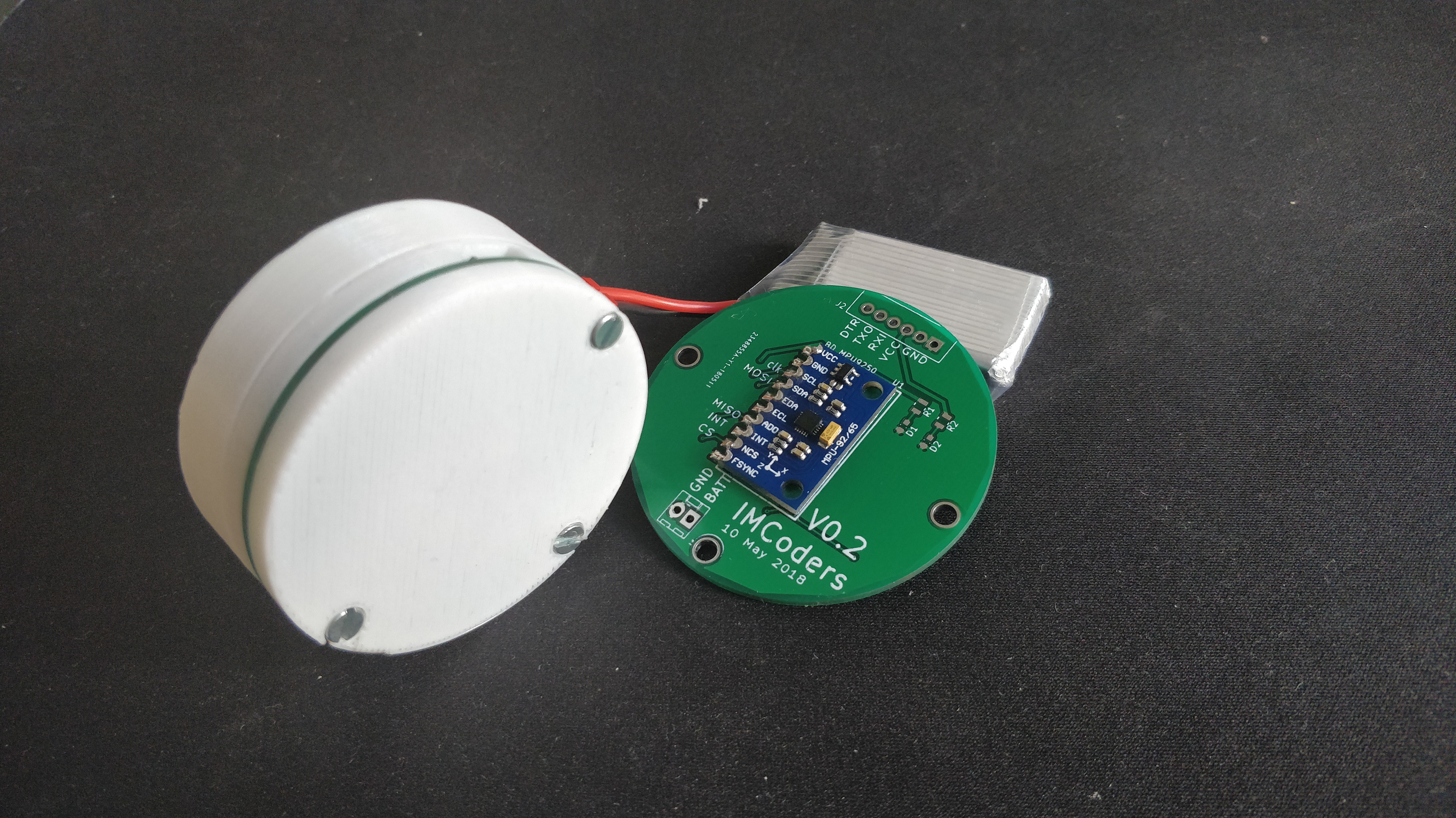
IMU -> Encoders = IMcoders
The main component of an IMcoder device is an IMU (Inertial Measurement System), a device equipped with three sensors: Accelerometer, Gyroscope and Compass.
The traditional use of IMUs as source of odometry data has been deeply studied and it has been proved not to be the best option as odometry data source in the long run (with a double integration of the acceleration to obtain position the acummulated error grows really fast). All the measurements are relative to the robot’s previous position and they are not absolute to the environment where the robot is moving. The error of each measurement of the sensor is accumulated in the next measure and, at some point in time, it makes the output of the system not reliable anymore. This effect has always been the restricting factor to use this devices as an standalone odometry source.
Our approach is not to use the bare output of the IMU as the input data to generate an odometry output but to use this IMU data to infer the spatial orientation of the wheel the sensor is attached to. Then, analyzing the spatial orientation of the wheel over time we can mimic the behaviour of the traditional encoders + some extra interesting features.
This approach has several advantages:
As the measurements of the IMU are relative to the object where it is attached, the physical constraints about where to mount the system are minimal.
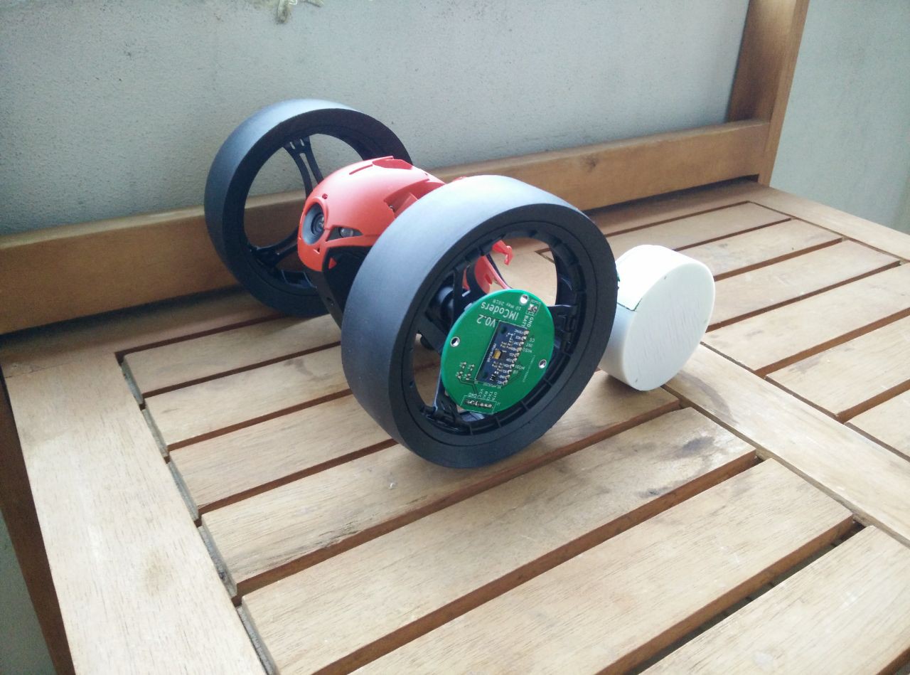
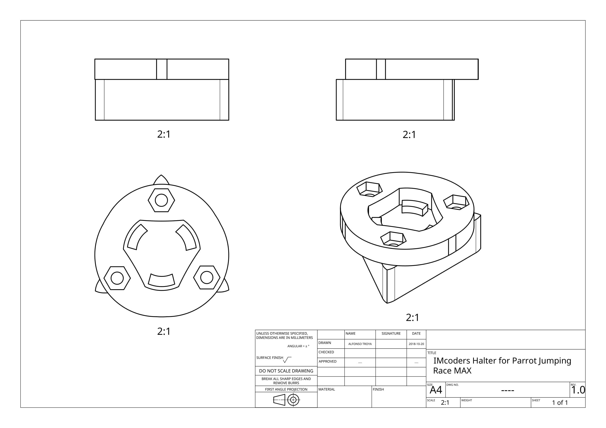
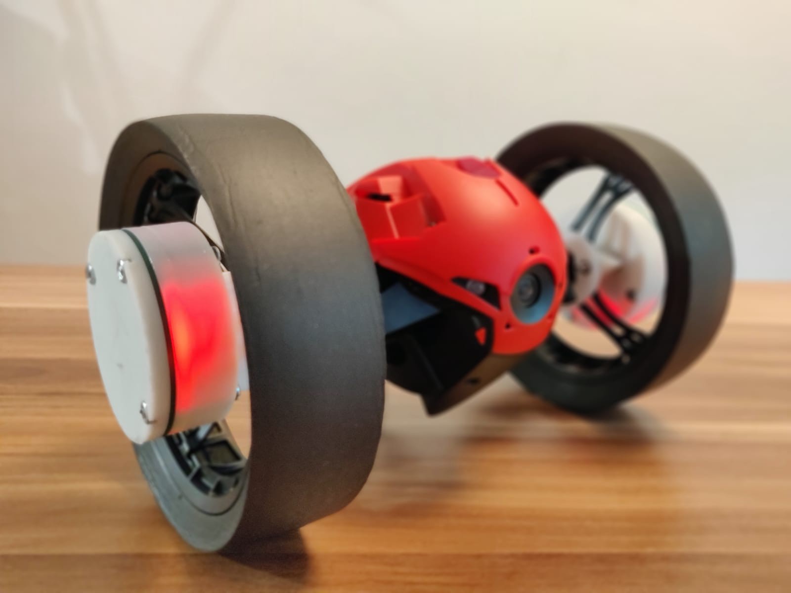
The IMcoders sensors can be easily attached to any exposed part of a wheel, as the sensor works rotating WITH the wheel.
The IMcoder sensor has an internal battery and includes a bluetooth module to wirelessly communicate with the host processing the data. This wireless communication approach removes the problematic of wires and simplifies even more the attachment of the sensor to the robot.
As the IMcoders directly measures acceleration, angular velocity and magnetic field on the wheel, we can infer much more information from this data source than just the orientation, as we proceed to explain:
Drifting Detection - Acceleration:
Imagine that in a static state (robot is standing still) the IMcoder sensor measures a high value on angular speed (the wheel is spinning) but there is almost no change in the magnitude of the measured acceleration (there is no change in velocity from the static position). Then, it is highly probable that the device...
Read more »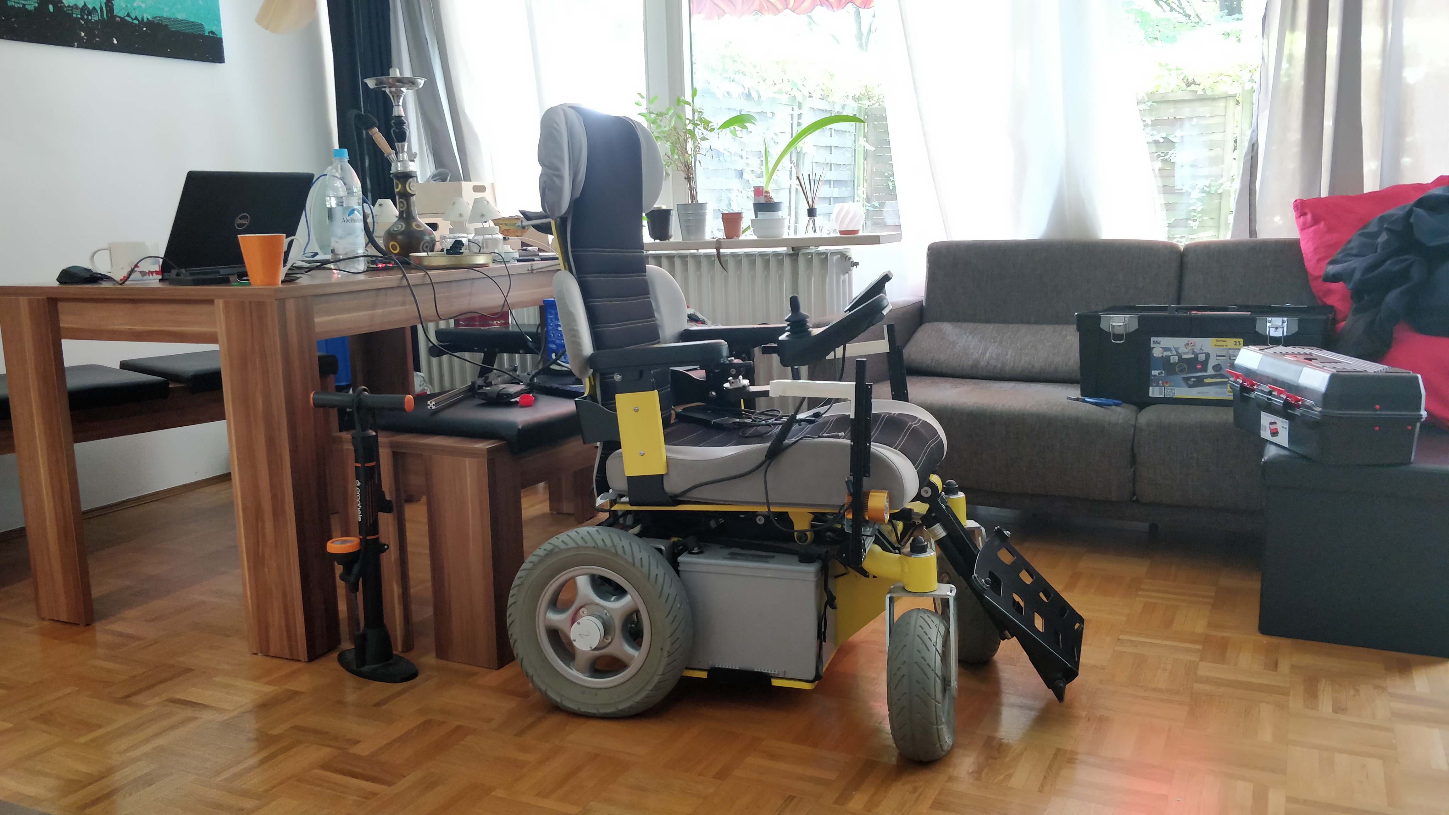


 Bonez
Bonez
 mircemk
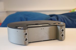
 Lars
Lars
 Mihir Garimella
hello, this project that you raise very interesting because it is an alternative to traditional encoders (incremental or absolute), help with this, how do you load the calibration file (RTIMULib.ini) in the ROS node?