Close
0%
0%

Libre Gates

A Libre VHDL framework for the static and dynamic analysis of mapped, gate-level circuits for FPGA and ASIC. Design For Test or nothing !

Similar projects worth following
As the project "VHDL library for gate-level verification" (https://hackaday.io/project/162594 ) was progressing, more features and more abstraction were developed, such that libraries other than the ProASIC3 family could be implemented. ASIC libraries such as sxlib or wsclib are good candidates, and more will appear with the surge in DIY ASIC projects spurred by Google & Skywater.This project brings its pure GHDL-driven code to more technologies, allowing users to check their circuit, verify BIST coverage and eventually generate test vectors with only a set of really Libre files in pure VHDL (thus avoiding expensive and restrictive license fees from niche proprietary vendors). Oh, did I mention how awesome GHDL is ? But you could use any simulator that is fully VHDL'93 compliant.Import from, and export to other netlist formats are also in the air...

This project contains a set of tools that process VHDL files mapped to FPGA/ASIC/arbitrary logic gates, so it is useful as a step between the synthesis of a circuit and the place&route operation. This is an exploratory toolset, constrained to a specific step of the logic design workflow, as it does not modify or transform the source netlist but gives insight into its often invisible structure, and guides the designer while writing it, in an interactive, iterative process, while focusing on specific digital units. As such, it is complementary but not a replacement of abc or yosys, which have way broader reach and features.

You can:

  • Simulate the circuit (for example, if your synthesiser has mapped the gates to a given PDK but you don't have the corresponding gates definitions in VHDL)
  • Perform static analysis of the netlist (spot unconnected inputs or outputs, and other common mistakes, beyond what VHDL already catches by default)
  • Extract dynamic activity statistics (how often does a wire flip state, if at all, during typical operation ?)
  • Verify that any internal state can be reached (thus helping with logic simplifications)
  • Alter any boolean function, inject arbitrary errors, optimise and prove your BIST strategy
  • Extract logic traversal depth and estimate speed/latency (roughly)
  • Inspect logic cones, see what inputs and outputs affect what
  • Help with replacing DFFs with transparent latches
  • Ensure that the circuit is correctly initialised with the minimal amount of /RESET signals (saving routing and area)
  • Detect and break unexpected logic loops or chains

Some day, it could be extended to

  • Pipeline a netlist and choose the appropriate strategy (will require detailed timing information, yosys probably does this already ?)
  • Customise the set of available gates to emulate or substitute arbitrary PDK/ALIs.
  • Transcode/Transpile a netlist from one family/technology/ALI to another
  • Which also means the ability to create custom ALIs from analysis of a design unit...
  • Import/export to Liberty, EDIF, Verilog, FPGA bitstream or others ?

 
Note: Since the tool typically processes netlists before place&route, no wiring parasitics data are available yet so no precise timing extraction is possible and it doesn't even try. It can however help, in particular with extraction of the criticality of each path then the mapping of gates to the proper fanout.

The project started as #VHDL library for gate-level verification but the scope keeps extending and greatly surpasses the mere ProASIC3 domain. For example I also study the addition of the minimalist OSU FreePDK45. More unrelated libraries would be added in the near future, depending on applications : Skywater PDK, Chip4Makers' FlexCell and Alliance could follow. Contact me if you need something !

-o-O-0-O-o-

Logs:
1. First upload
2. Second upload
3. Rewrite
4. More features ! (one day)
5. Another method to create the wrapper
6. inside out
7. OSU FreePDK45 and derivatives
8. The new netlist scanner
9. Chasing a "unexpected feature" in GHDL
10. Polishing and more bash hacking
11. Completeness of a simple heuristic
12. Benchmarking with a HUGE LFSR
13. Benchmarking results
14. Wrapper rewrite
15. A smarter sinks list allocator
16. Strong typing snafu
17. Plot twist
18. Skipping the preflight check
19. Depthlist v2
20. Better detection of driver conflicts
21. Custom mode with arbitrary ALI
22. More async
23. Meanwhile, GHDL...
24. Update 20220528
25. ALIberty
26. Two outputs and more inputs
27. ALI definition
28. The taxonomy of Set/Reset latches
29. More inputs ? No, finer gate delays.
.
.
.

LibreGates_20220528-1.tbz

Better XML parser

x-bzip-compressed-tar - 227.77 kB - 05/28/2023 at 04:15

Download

LibreGates_20201216.tbz

better driver conflict detection

x-bzip-compressed-tar - 227.47 kB - 12/17/2020 at 03:02

Download

LibreGates_20201209.tbz

netlist probe v2B : passes more tests

x-bzip-compressed-tar - 224.35 kB - 12/09/2020 at 05:18

Download

LibreGates_20201202.tbz

netlist probe ok

x-bzip-compressed-tar - 224.07 kB - 12/02/2020 at 03:17

Download

LibreGates_20201128.interim.tbz

rebuilding the netlist probe code.

x-bzip-compressed-tar - 234.94 kB - 11/28/2020 at 09:32

Download

View all 13 files

  • More inputs ? No, finer gate delays.

    Yann Guidon / YGDES06/27/2023 at 02:43 0 comments

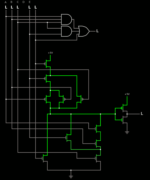
    In the log about CLA3 in another project, I study how a 5-input gate could boost a Carry Lookahead Adder that is already part of the test suite. I'm talking about this circuit:

    Some of the gain comes from sharing one input signal with two AND gates. This and a few other things make me consider the legitimacy of increasing the size of the LUT that LibreGates uses in the advanced mode. It's a seducing idea but... Where is the limit ? How many inputs will be enough ?

    As noted in the #analoglib project, gates with a maximal number of traversed transistors of 3 can have up to 3*3=9 inputs, though this extreme case is not very practical due to routing constraint in an ASIC cell. But this is way above the 4 inputs that the current system uses now. And CLA3 is a useful gate, there may be others.

    So let's say, the maximum size is 8 inputs. That's a LUT with 256 inputs, which also means 256 test vectors to generate for just one gate, which is not reasonable. Even the CLA3 gate, with the 5 inputs, requires 32 vectors.

    Fortunately this is easy to break down, as shown in the following circuit. The ANDs can be grouped in a LUT4 and OR-combined with a OR2 with the 5th input. That's a total of 16+4=20 LUT entries, hence 20 test vectors.

    Now something gets in the way of this pretty picture : this composite gate is considered as 2 gates of delay/depth 1 each so if I create a macrogate, it will be seen as depth 2, while the equivalent cell has a delay of (mostly) 1. So the macrogate will give relevant results for the ATPG but the circuit complexity or depth will be misleading.

    The solution I have found so far is to add a generic to each gate that gives a slightly more accurate idea of the relative complexity and delay. In the macrogate, the gates can be given smaller values than the individual gates alone, thus giving an overal sum that is closer to the real thing.

    Of course the backwards metagate has a delay of 0 but all the others must start with an arbitrary constant cost of say, 1.  An inverter adds 1 pass transistor so the total delay is 2. NAND2 has a total of 3 and NAND3 has a delay of 4.

    CLA3 has a maximum of 3 transistors in series, so it's 1+3=4, but there is an added inverter. Since it does not go out of the cell, the total cost is only 5. All of this is arbitrary of course but depending on the way the delays are estimated, it could give a better estimate of the performance of a circuit. And we can add the fanout to the estimates as well.

  • The taxonomy of Set/Reset latches

    Yann Guidon / YGDES06/09/2023 at 18:16 0 comments

    In the source code of LibreGates, one can find a file named LibreGates/SRFF_simple.vhdl and this log explains its purpose, because it is well justified despite opinions of the contrary. The following is a summary of the discussions with @alcim.dev. Let's start by looking at the header:

    -- file LibreGates/SRFF_simple.vhdl
    -- created mar. août 25 02:51:59 CEST 2020 by whygee@f-cpu.org
    -- version mar. sept.  1 04:02:57 CEST 2020 : LibreGates !
    --
    -- This is the basic version and the initial definition for
    -- various Set/Reset Flip-Flops, defined by the precedence
    -- of the control signals and their active levels.
    --
    -- Precedence  Set  Reset  Macro
    --            level level  name  Mapped to
    --      Set     0     0    S0R0   AO1A
    --      Set     0     1    S0R1   AO1C
    --      Set     1     0    S1R0   AO1, AON21
    --      Set     1     1    S1R1   AO1B, DLI1P1C1, AON21B
    --    Reset     0     0    R0S0   OA1A
    --    Reset     0     1    R1S0   OA1C
    --    Reset     1     0    R0S1   OA1, OAN21
    --    Reset     1     1    R1S1   OA1B, DLN1P1C1, OAN21B
    --
    

    You already certainly know the basic Set-Reset Flip Flops and this file implements them, though at a very abstract level, such as:

    architecture simple of S0R1 is begin Y <= '1' when S='0' else '0' when R='1'; end simple;

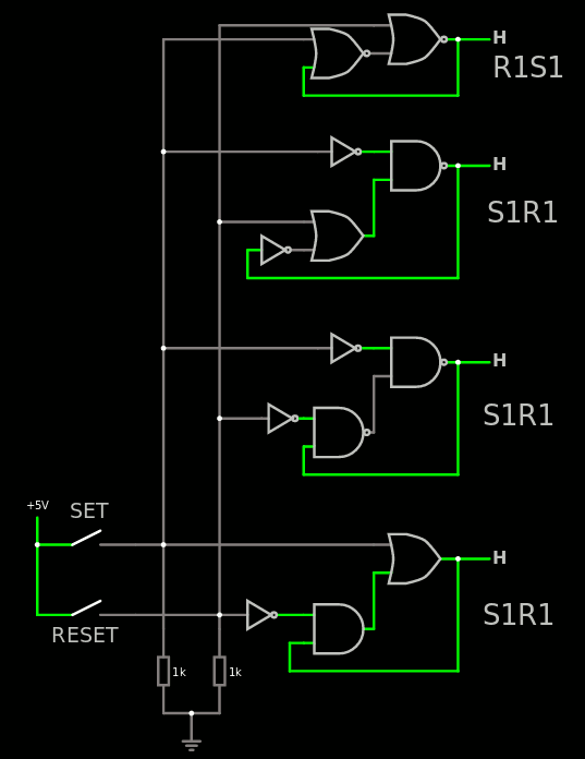
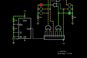
    So there is not much to say on this level, it's plain and dumb. But there are 8 versions, each one of the 2×2×2 combinations of precedence (set or reset), active level for set and active level of reset. As the header notes, each of these versions can be implemented with more than one circuit. The example below shows how to make S1R1 in 3 different ways:

    You can try the circuit on circuitjs with this link.

    The first property of these "macrogates" is that they should not oscillate when both inputs are active (unlike some highly-frowned-upon circuit topologies that can be found here and there).

    The second property is that there is a clear priority : one signal has precedence over the other. For example R1S1 at the top has the same active level but behaves differently when all switches are closed.

    A third property is that even though they are represented here by 2 gates, they can also be implemented by a single composite gate, as listed in the header (using the A3P terminology though, YMWV).

    This collection is an exhaustive taxonomy that is useful during design as well as optimisation, and the SxRy and RxSy definition is abstract enough that design is not too encumbered and optimisation is easy.

    • During design, the designer knows that all combinations are possible so there is no restriction or constraint to get something done. There is a clear priority and the levels can be changed at will, knowing that an optimal implementation will be available later.
    • During optimisation, there are two more benefits :
      • the gate can be selected and changed to favour speed in the high-speed critical datapath, by selecting an implementation that has the least logic depth at the right place. The other input can come from a "slow circuit" with less of speed constraint, like an outside control or debug signal.
      • the gate can also ease bubble-pushing because all level combinations are possible (2 inputs, one output, yeah that makes 8 combinations).  Bubble-pushing can stop or start when reaching the SRFF gate, and be changed or adapted appropriately.

    Of course this type of gate is not used in the heart of a high-speed circuit. This is necessary when clock domains meet and a signal must cross them, usually with some kind of handshake. It is particularly important for debug/monitoring/control/test circuits, as well as asynchronous I/O ports (for example with serial circuits where the clock comes from outside).

    Debug circuits can become quite complex and this little meta-library provides the designer with enough flexibility to get things done right. It is up to the designer and upstream providers (ASIC PDK, FPGA...) to then map the metagate to the appropriate standard (or custom) cell.

    One example is the R1S1 gate made of two NOR2 gates at the top. It is pretty optimal, transistor-wise and it can be mapped...

    Read more »

  • Two outputs and more inputs

    Yann Guidon / YGDES06/08/2023 at 23:31 0 comments

    Digging through various .lib gathered from around the 'net, it appears that sequential cells (flip-flops, transparent latches and set-reset latches) are often described with the Q and /Q outputs simultaneously. There is some advantage to this :

    • You may want to decrease the output fanout so you split it over two related outputs
    • You may want to ease bubble-pushing, and the dual/complementary output offers a convenient "conversion" point with some sort of "free inverter".

    So I'll have to find a way to include that in the code...

    Furthermore, I often get annoyed by the redundancy that is often found inside cells, which makes it harder for the synthesiser to factor some signals, in particular inverters : you can find them in many gates such as XOR, MUX and even DFF. Often, these signals are driven by a common source, such as a clock net, a control signal, and spread to tens of gates (let's say N). So the common signal is sent to N gates with a fan-in of 2 because it must drive the gate and the inverter. Such a fanout creates delays.

    Sending a pair of complementary signals lowers the fanout/fanin constraint, so it should be 2× faster (up to...). It also makes place&routing more complex, particularly if it's a dumb algo that doesn't care about the geometry...

    But this makes the case for "grouped cells" with one clock or control input signal which is locally amplified to 2 or 4 neighbouring cells. I have seen this recently in a paper or something...

    Again, this is an optimisation step, where energy, space and time are progressively enhanced by making some custom cells to solve some local inefficiencies.

    -o-0-O-0-o-

    Meanwhile I also see some cells with more than 4 inputs.

    Currently the system uses up to 4-input LUTS, and quite a bit of obscure code depends on this. But I have seen some larger combinatorial gates such as MUX4, and the adder uses a macrogate containing AND2, AND3 and OR3 with 5 inputs. A LUT5 has 32 entries, while the individual gates total 4+8+8=20 entries, so testing them requires fewer test vectors than a custom macrogate. OTOH the macrogate saves interconnect/routing resources, since it knows how to keep some traces directly at the cell level, without going through the tortuous metal layers.

    I guess a cell would need to be crazy complicated or incredibly more efficient to justify going to LUT6. Even LUT5 would require some rewrites here and there. I also see some cells FA and HA : Full Adder and Half Adder, with 2 or 3 inputs and 2 outputs. This last case is a bit easier to handle since each "macrogate" can be "splitl" into two 1-output gates :

    • half adder is just a AND and a XOR so it can be described as these two gates internally
    • full adder is a XOR3 and a MAJ3 which can also be built from individual gates.
    • Same idea with MUX4 : it can be internally built from three MUX2 at least for the purpose of test vector generation.

    Anyway, with @alcim.dev  the exploration and design of libraries of gates is progressing.

  • ALI definition

    Yann Guidon / YGDES05/29/2023 at 13:54 0 comments

    So the idea is simple, I need an intermediate file format to define the logic gates of a library.

    Doing a direct translation from Liberty or other formats to VHDL would be too complex so I do in two steps, the first being the refactoring of the existing tool.

    The constraint is to KISS : keep it simple and even stupid, and a lot of complexity comes from parsers. The XML parser in bash is an example of overly crazy code that breaks and must be maintained in synch with the tool that generates the XML. But GHDL doesn't evolve fast and there is only one tool to read from. For Liberty, it's a totally different beast... Too many origins, too many tools, too many options and variations... I have collected a few .lib files from different origins and I welcome new ones to test my system.

    But first I must define what the .lib parser must output, which should be as easy as possible to process on my side. The format is a text using a widely used function syntax, instead of a JSON or XML format, because I can directly process it in VHDL, C, JS, you name it. It gets parsed by the interpreter or the compiler, so that's as much I don't have to do.

    First, define the library name:

    define_library_name("somenamewithoutspace");

    It must be called first and only once.

    Then more calls are needed to define each cell/gate, which is either a combinatorial gate (could be a buffer too), a synchronous FlipFlop or an asynchronous Set/Reset latch.

    define_combinatorial_cell("AND", "A and B", "Y", "A", "B");
    define_sequential_cell("DFF", "Q", "D", "CLK", "CLR");
    define_asynchronous_cell("RSLATCH", "Q", "S", "R");

    The calling convention is still preliminary and will evolve. But the syntax follows the classic conventions and the calls end with a ";" (strip it if you want to use Python)

    So far the limits are the multi-output cells (such as HAX1 and FAX1 of OSU) and the translation of AND, XOR and OR from the weird conventions of the Liberty format, as defined p96, section 4-36:

    function : "Boolean expression" ;
    
    The precedence of the operators is left to right,
    with inversion performed first, then XOR, then AND, then OR.
    
    Table 4-6 : Valid Boolean Operators in the function Attribute Statement
    
    Operator Description
      ’      Invert previous expression
      !      Invert following expression
      ^      Logical XOR
      *      Logical AND
      &      Logical AND
    space    Logical AND
      +      Logical OR
      |      Logical OR
      1      Signal tied to logic 1
      0      Signal tied to logic 0
    

    So the Liberty parser's role is to deal with this mish-mash and output VHDL-correct boolean expressions. We'll see that later.

    For now the idea for the flow is

    1. get the .ali file with all the calls
    2. script to add "decoration" to the list and create a function out of the file, following the language's conventions.
    3. The target language will also have definitions of the functions.
    4. The target language then call the custon function, that calls the subfunctions with the user's data/parameters.

    For the VHDL version, the gate functions will be called twice : for the declaration then the definition. The gate functions must know which phase they are called from so they output the right text. And since they could be called in any order (you never know, bugs happen) they must also check it too.

    The first thing to do now is to convert the A3P (and maybe OSU and others) libs to the ALI format, by hand, and see how to refarctor the tools to accept these.

  • ALIberty

    Yann Guidon / YGDES05/28/2023 at 23:01 0 comments

    More discussions and looking around later, it appears that Liberty files, created back in the 80s by Synospsys, contain a field that might be an afterthought but is critical for my purpose, and Liberty files are the standard way to exchange ASIC cell characteristics. Here is how one cell is described :

    /* --------------- *
     * Design : AND2X1 *
     * --------------- */
    cell (AND2X1) {
    area : 72;
      cell_leakage_power : 0.12537;
      pin(A)  {
        direction : input;
        capacitance : 0.0181648;
        rise_capacitance : 0.0181286;
        fall_capacitance : 0.0181648;
      }
      pin(B)  {
        direction : input;
        capacitance : 0.0178174;
        rise_capacitance : 0.0178174;
        fall_capacitance : 0.0176984;
      }
      pin(Y)  {
        direction : output;
        capacitance : 0;
        rise_capacitance : 0;
        fall_capacitance : 0;
        max_capacitance : 0.497268;
        function : "(A B)";
        timing() {
          related_pin : "A";
          timing_sense : positive_unate;
          cell_rise(delay_template_5x5) {
            index_1 ("0.01, 0.025, 0.05, 0.15, 0.3");
            index_2 ("0.06, 0.18, 0.42, 0.6, 1.2");
    .......

    This is from osu025_stdcells.lib (TSCM 0.25µ library). This open directory also provides the VHDL VITAL model, where the logic gates are described in great detail for the timing in particular. But that's not what I'm here for : I work at the earlier stages in the boolean domain. VITAL simulations will be useful later for detailed simulation, after all the fault injections have been dealt with.

    Liberty is probably the most popular format for a SDK to provide timing characteristics. Most EDA prefer Verilog and as highlighted above, the gates contain the function, which I could extract. I could reenact my feat as I did with the custom XML parser (written in bash) but I have cold feet as the XML parser is only intended to read from one tool in particular, with a very specific format, while Liberty is used and generated by a wide variety of tools that I hope to interface with. I don't know yet what I am facing.

    I only need to regenerate the basic gate function, so I just want inputs pins, output pin, and a boolean function between them. All the rest is then processed by LibreGates. Meanwhile I realise that my system (like so many others) only handles gates with one output.

    There are some useful resources online, such as the Synopsys document for the format and a Python parser. Extracting the gate names, functions, pin names will not be too hard. However I need to make it work with the existing code so I consider using an intermediate file format that will make the VHDL generation easier and more modular. It will hopefully split the complexity between the Liberty filter and the VHDL metaprogramming mess.

    One of the little issues I'll have to deal with is the description of the boolean equations of the Liberty format : AND has no operator sign...

    The other issue will be with the sequential gates, as they are way more diverse than the boolean gates.

    I think I have an idea for the intermediary format, using function calls to be directly executed and cut down the parsing requirements.

  • Update 20230528

    Yann Guidon / YGDES05/28/2023 at 00:35 0 comments

    The new version is here !

    I mostly solved some bash script hiccups. I haven't even started implementing the ALI or the VHDL netlist analyser. I just wanted it to work with the newer versions of Bash and GHDL (I have only v1.0 on Fedora, while v3 is already out, I know...)

    This is some warmup and I also test my new platform : 6 cores and SSDs, so the 5 tests complete in only about 18s now, down from 42s.

    ...

    Oh wait now it doesn't work with the older version 0.35 :-/

    So I put a bit more effort in the XML parser (written in bash) so it understands references. LibreGates_20220528-1.tbz has the updated files.

    ....

    Oh and I missed a year, we're already in 2023 it seems.

  • Meanwhile, GHDL...

    Yann Guidon / YGDES05/26/2023 at 19:04 1 comment

    ... evolves !


    I did a lot of work and dev using the 2015 tarball version (0.35-dev packaged by RedHat in 2017) and today Fedora 38 has v1.0-dev, while v3.0 has been released a few weeks ago. I'd like to get it on my computer but there is no .RPM yet.

    This breaks some scripts and I'll have to hack and reverse-engineer more to get the scripts functional again. This would enable me to resume work on some borked/incomplete parts of the tools...

    I haven't touched the codebase in 2 years now and it's getting a bit dusty :-/

  • More async

    Yann Guidon / YGDES05/26/2023 at 11:06 10 comments

    @SHAOS  made me discover the "C-element" in his log Trying other ways to make chips. I don't know why I hadn't heard about it yet. It's something to keep in mind for when I have resurrected the project and after I added the ALI. The tools have a setback for a few reasons, one of them being the need to support asynchronous logic and clock domain crossings... This way I'll be able to fully characterise the debug interface of the #YGREC8.

  • Custom mode with arbitrary ALI

    Yann Guidon / YGDES04/07/2023 at 13:00 0 comments

    LibreGates is an abstraction and generalisation of a "PDK" or gates library originated in #VHDL library for gate-level verification. As such it is useful as a "design space exploration" tool for top-down optimisation. It started as a simple alternative barebones library for distribution of Libre designs targeted at the now obsolete Actel ProASIC3 FPGA, helping to keep the optimised designs alive despite vendor lock-ins.

    So the original library grew to a general, multipurpose one with bells & whistles, trying to provide all the possible functions one might desire or need. It can be used as a generic collection of gates for prototyping, without thinking too much about logic optimisation or platform limitations at first. Only once the design space is explored and constrained, one commits to the chosen technology, its PDK and its specific list of gates and functions, then maps the gates. But this might not be convenient. For Libre projects, it is desirable to be able to provide a dumb gates library along with the design source files, for when the PDK is not available. So far only the full generic LibreGates definition file is provided.

    Or, one might start from a given PDK but the gates names and pin assignments do not match the gates that LibreGates defines. Talking with @alcim.dev, something became apparent :

    Software stacks use API and ABI so why not create an ALI ?

    After all, each PDK and logic device forces its own Application Logic Interface to the user through a selected list of allowed logic functions. So far all these types of applications are siloed, entrenched. They barely talk to each other and any choice will overly specialise an optimised design to the selected technology. And LibreGates tries to bridge them all for design portability so we need a formal definition of the ALI.

    So the TODO list gets a new item : after I finish the code for the backwards gates, I'll add the support for an external definition file (.ALI) that will enable LibreGates to define and regenerate any desired subset of gates. Any PDK or platform can thus be distilled down to a language independent file.

    For now I consider customising:

    • Library name
    • gate name
    • mapping to the internal LibreGates name
    • pin assignment / swap (later)
    • fanout/drive ? (for later)

    Note : other extra analog data such as per-input delays are irrelevant so far. Parametric values might be unavailable or ignored for now as it is too high level for these shenanigans.

    The format will be crude at first so I don't need to rewrite Flex and Bison in VHDL. So maybe I'll have to write a JSON parser in VHDL someday.

    This way, anybody can generate their own VHDL library (or other language later, like Verilog ?) with their own namespace, and distribute the generated library file in the same AGPL licence as the rest. (Why AGPL and not LGPL ? Because the library is not meant to be part of a shipped product since it is a temporary substitute to the final gates lib).

    This is a big deal because so far, we speak of "technology" as both the physical parameters and implementation (think : discrete transistors, TTL, NMOS, PMOS, IIL, CMOS, ECL, FPGA, you name it) and the "logic language", the available set of boolean operations permitted by said technology. The huge driving force for designing LibreGates is the ability to port and refine a circuit, from TTL to FPGA and from ECL to NMOS. Or simply map a high-level circuit to any of these. And since now @alcim.dev wants to port his LogiLib, more flexibility is required, without touching the core source files of LibreGates. 

    So for example an ALI for discrete CDC-style gates (implemented with discrete saturated transistors) would contain half a dozen gates only, with mainly NOT, NOR2, NOR3, NOR4 and latches. ECL ALI would have these and some more others like XOR. TTL ALI gets NAND2, NOR2, XOR and the likes (though LibreGates is limited to 4 inputs). The OSU FreePDK defines only 33 gates. No need to modify any internal code or gate...

    Read more »

  • Better detection of driver conflicts

    Yann Guidon / YGDES12/16/2020 at 04:03 0 comments

    The new netlist probe algo has a better inherent sensitivity to driver conflicts, which should not occur in normal netlists but VHDL usually favors the std_logic type, which is a resolved version of std_ulogic that has less adoption despite its inherent ability to detect these driver conflicts.

    The netlist probe detects a conflict because a resolved value is "likely" to differ from a valid signal signature. To ensure some margin, the signature is given by a simple polynomial using the driver's number : a multiplier and an offset, both of which are primes.

      -- The polynomial parameters:
      shared variable Poly_factor : integer := 13;
      shared variable Poly_offset : integer :=  5;
      -- Ideally, choose both as prime numbers, and the
      -- offset MUST be less than the factor (one half is good).
      -- The compromise is between execution speed (each
      -- factor of 8 adds another probe cycles) and
      -- error discrimination (fewer chances of coincidence).
    

    I have enabled the test of this features in test4_cornercases:

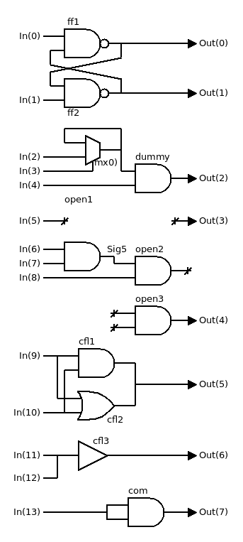
    The gates clf1, cfl2 and cfl3 detect a driver conflict on an output port and a gate input. But it didn't work immediately: this depends on the polynomial factors, and some (which ?) will work and others not. 17-7 didn't work for this test, but 13-5 did, YMWV.

    At first glance, the chance of detection will increase with the poly factor, but this also increases the number (and runtime) of the probe.

    • If you are sure there is no conflict, use 1-0 to save time, particularly for huge netlists.
    • 7-3 adds 1 probe cycle
    • 61-23 will add 2 probe cycles
    • 499-257 will add 3 probe cycles (new safe default)
    • You could run the probe several times with various factors but it is more efficient to use larger factors. Help yourself.

    Those values should be configurable with a generic one day.

    The first version of the netlist probe was also able to identify the drivers of a conflict, now it's only possible to show the sink, but at least it's faster.

    Each driver conflict is counted as an unconnected input and will abort the probe. It wouldn't make sense otherwise. Floating nodes are handled inside the gates.

View all 29 project logs

  • 1
    Download

    Get the latest package version from https://hackaday.io/project/174585/files

  • 2
    Build

    Execute the run_tests.sh script.

    This will build the libraries and run many self-tests.

    These examples in the tests directory also show you the various ways to use this library.

  • 3
    Link

    You can directly use this library with all the ProASIC3 standard files, either without the analytics system ("simple" version) or the full analytics system (the standard version).


    In the "simple" case, at full simulation speed and no analysis, your VHDL source code contains these lines :

    Library proasic3;
        use proasic3.all;

    Then you point GHDL to the right library with this command line:

    ghdl -Psomepath/LibreGates/proasic3/simple my_file.vhdl
     

    If you need full analysis, then use the standard version and add these invocations to the VHDL testbench:

    Library LibreGates;    use LibreGates.all;    use LibreGates.Gates_lib.all;

    Then you modify the inclusion path :

    ghdl -Psomepath/LibreGates/proasic3 my_file.vhdl

View all 4 instructions

Enjoy this project?

Share

Discussions

Yann Guidon / YGDES wrote 07/01/2023 at 04:01 point

https://pdk.libresilicon.com/ :-D

  Are you sure? yes | no

Yann Guidon / YGDES wrote 06/06/2023 at 20:52 point

Today I tested the latest bundle with GHDL4.0.0-dev and it was smooooth.

That's quite an upgrade from Fedora's broken 0.38 :-)

  Are you sure? yes | no

Yann Guidon / YGDES wrote 05/26/2023 at 19:06 point

Hey thanks @Dr. Cockroach  for following this project ! I have no idea if this could be used for your Light Logic gates but I leave this to you as an exercise ;-)

  Are you sure? yes | no

Yann Guidon / YGDES wrote 05/26/2023 at 16:50 point

https://fr.wikipedia.org/wiki/GHDL

Someone mentions this project on Wikipedia and I just that found today while trying to download the latest version of GHDL. Who did this ? :-D

  Are you sure? yes | no

Dylan Brophy wrote 05/26/2023 at 18:42 point

Woah - that's awesome!  Congrats!  I wonder if we will find out who did it...

  Are you sure? yes | no

Yann Guidon / YGDES wrote 05/26/2023 at 18:48 point

I'm too lazy to look at the changelogs.

And no it's not me, I would have cited other more relevant articles I wrote about it.

  Are you sure? yes | no

Dr. Cockroach wrote 05/26/2023 at 18:57 point

Yes, awesome is right :-)

  Are you sure? yes | no

Yann Guidon / YGDES wrote 01/27/2022 at 16:20 point

TODO: export to CUDA......

  Are you sure? yes | no

Yann Guidon / YGDES wrote 11/14/2021 at 08:26 point

TODO : FROM unit (128×8 bits of Flash)

  Are you sure? yes | no

Yann Guidon / YGDES wrote 12/19/2020 at 21:11 point

Welcome @llo and thanks for your help, past and present :-)

  Are you sure? yes | no

llo wrote 12/20/2020 at 08:18 point

what is your need at the moment ?

  Are you sure? yes | no

Yann Guidon / YGDES wrote 12/21/2020 at 03:57 point

still the same : beta-testing, compile reports with different config, naive/stupid questions about things I thought were obvious...

  Are you sure? yes | no

llo wrote 12/21/2020 at 10:17 point

@Yann Guidon / YGDES is there a github repository ?

  Are you sure? yes | no

Yann Guidon / YGDES wrote 12/21/2020 at 17:01 point

no, the usual snapshots .tbz on the page.

  Are you sure? yes | no

Dylan Brophy wrote 11/22/2020 at 06:25 point

"Design For Test or nothing !" - YES, good practice. Need more of this IMO.

  Are you sure? yes | no

Yann Guidon / YGDES wrote 11/22/2020 at 08:18 point

It must be the default.
Not just for HW but also SW.

  Are you sure? yes | no

frenchie68 wrote 11/22/2020 at 10:59 point

I wonder what you meant (wrt. software that is).

  Are you sure? yes | no

Yann Guidon / YGDES wrote 11/22/2020 at 11:13 point

I mean that systematic unit testing, thorough proofing/stressing/benchmarking are faint afterthoughts in most SW projects. People only query Google when they have a bug, a question or just want to learn how to do a specific task. Nowhere do I see tutorials about testbenches, it's mostly a culture where "it works so it's done".

One of the few exceptions is GCC where it is (was?) shipped with a suite of conformance self-tests.

But take any user-facing program and testing is "eventual" and "manual".

  Are you sure? yes | no

Does this project spark your interest?

Become a member to follow this project and never miss any updates