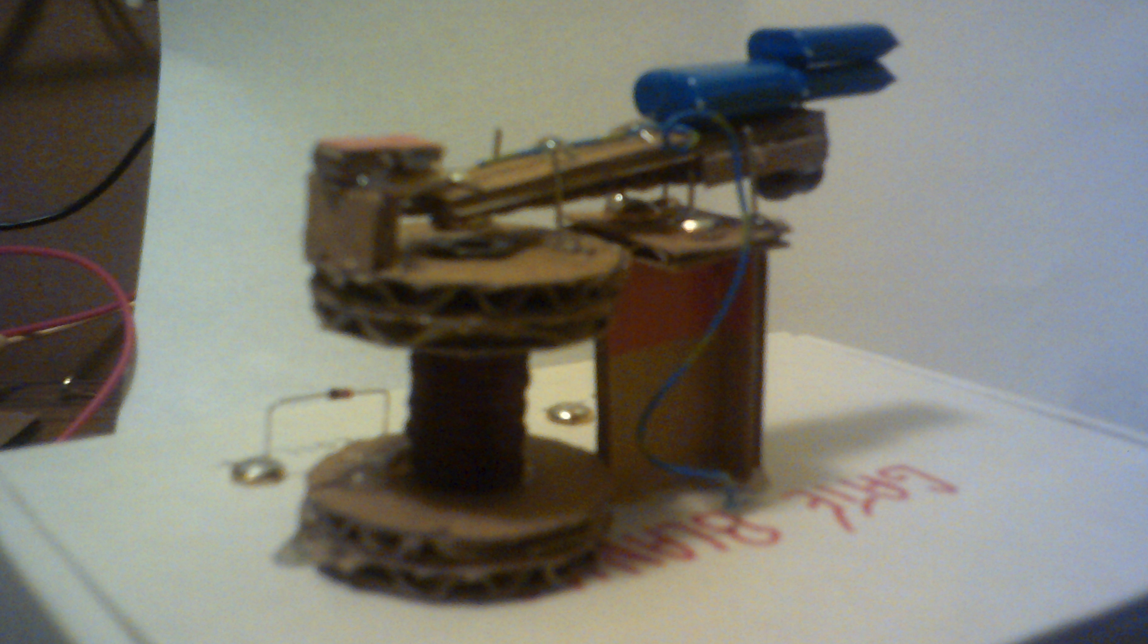
 Dr. Cockroach
Having a little fun with IO
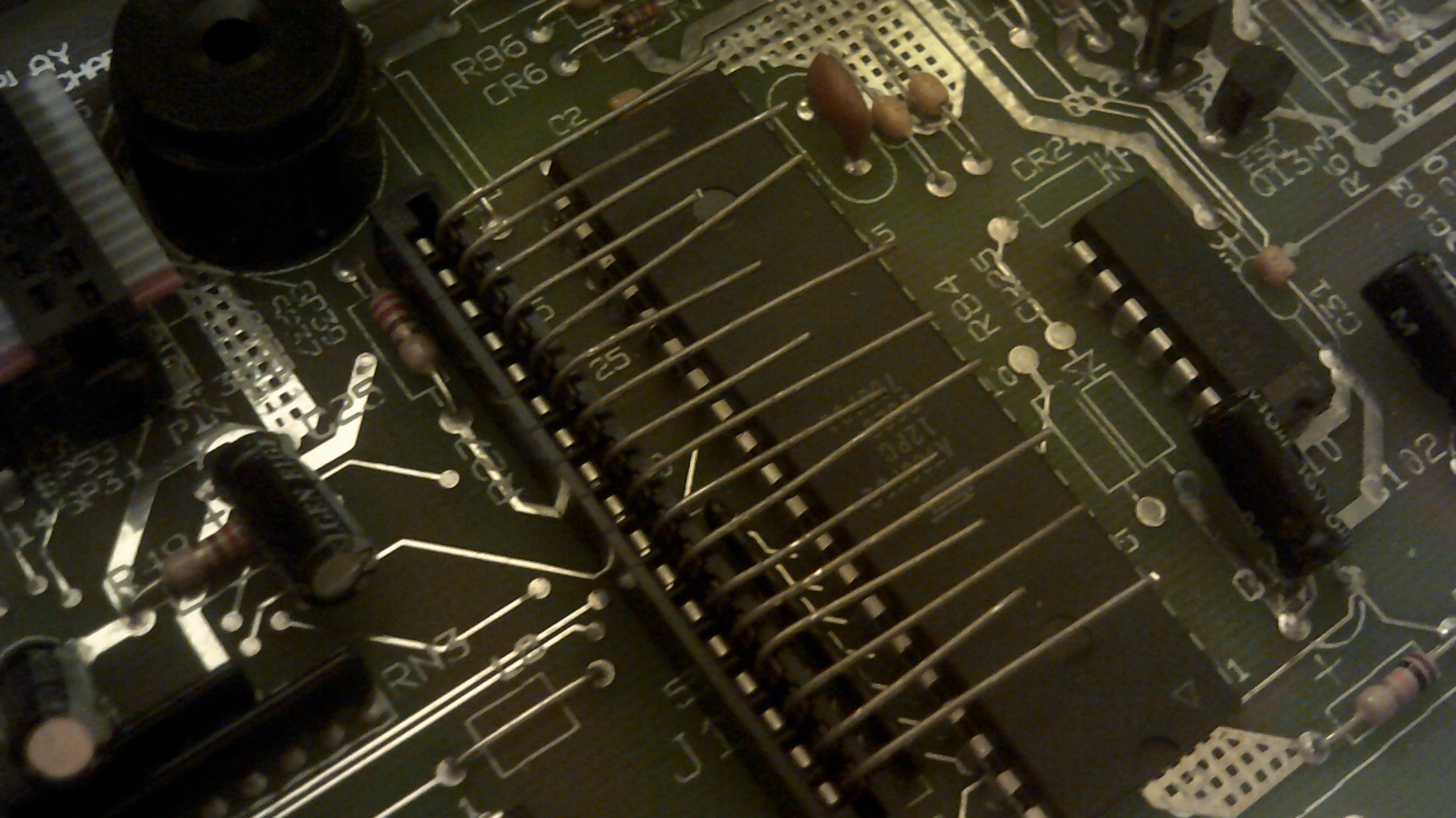
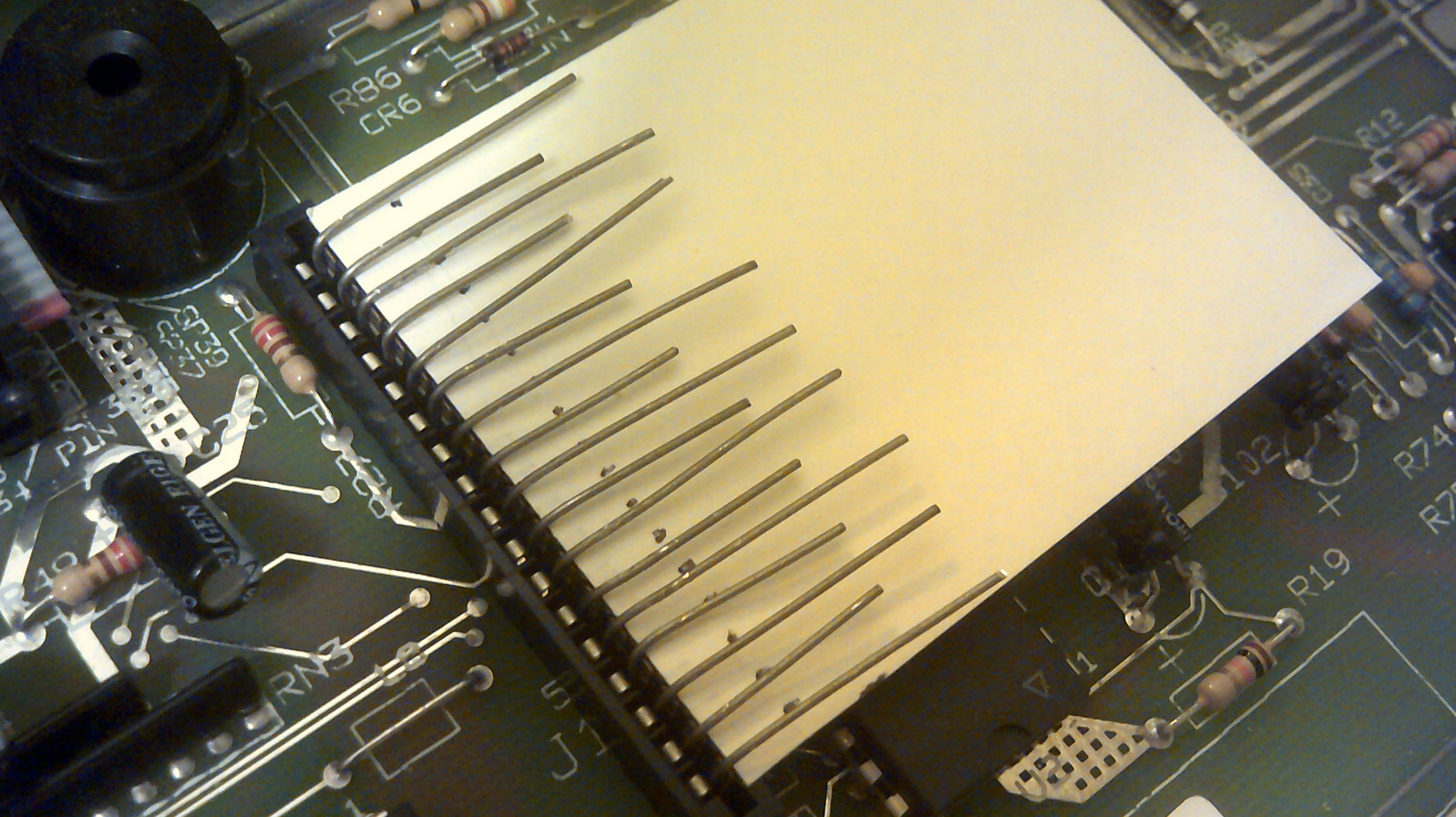
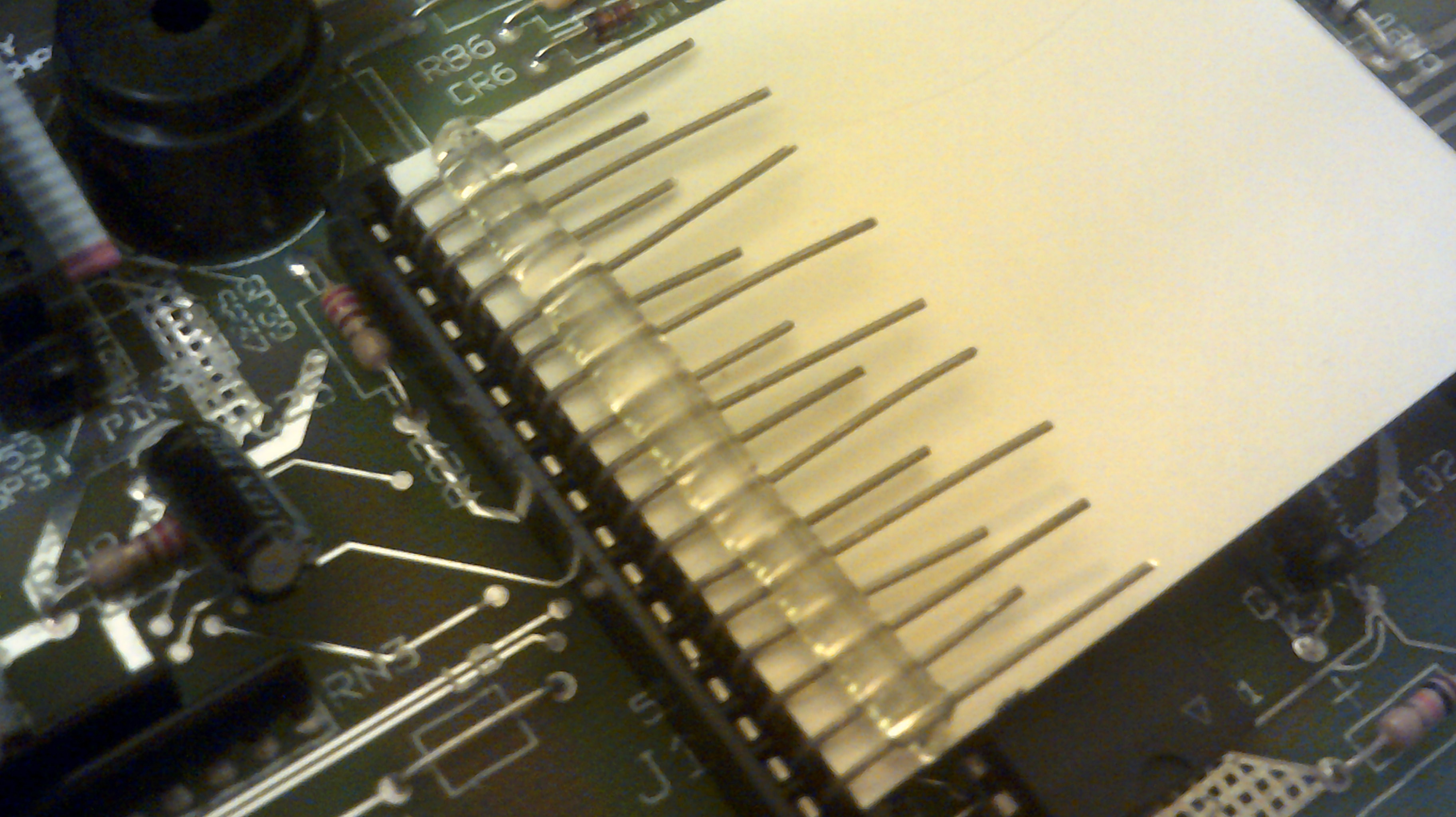
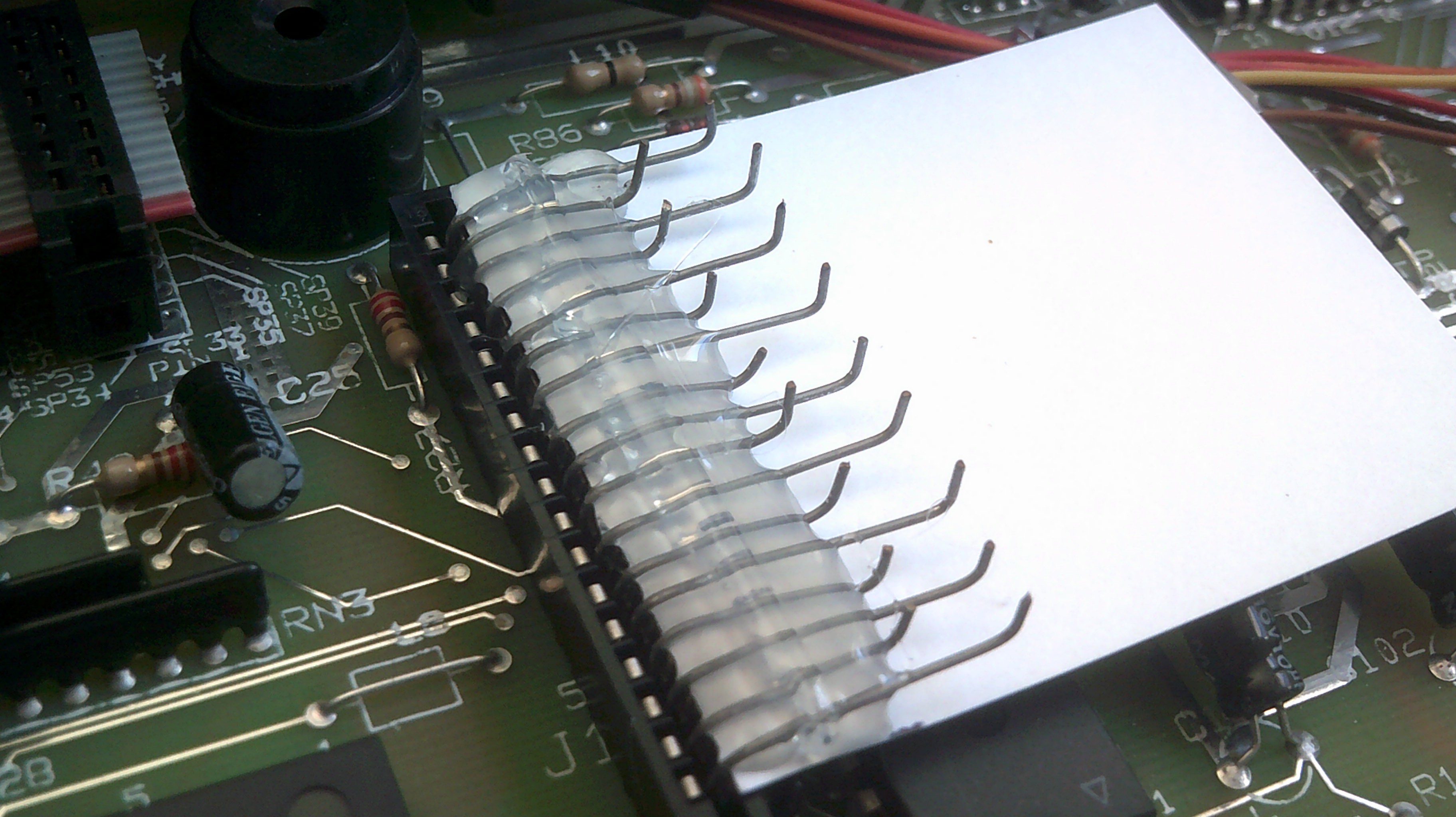
IO has printed its first word after some issues were cleared up.
Added a clock speed control to IO
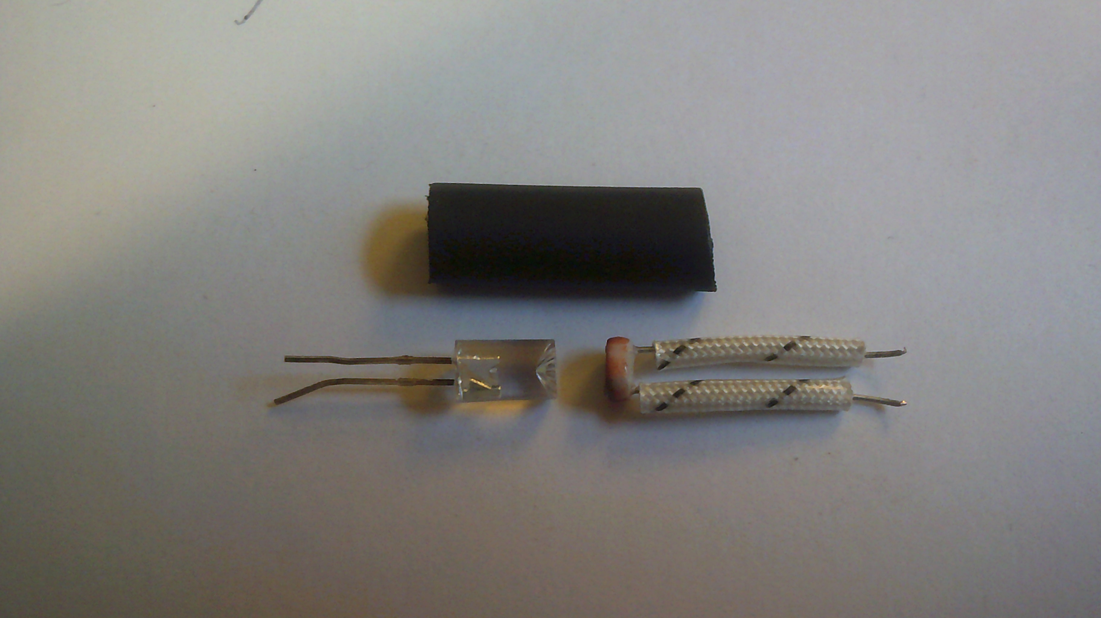
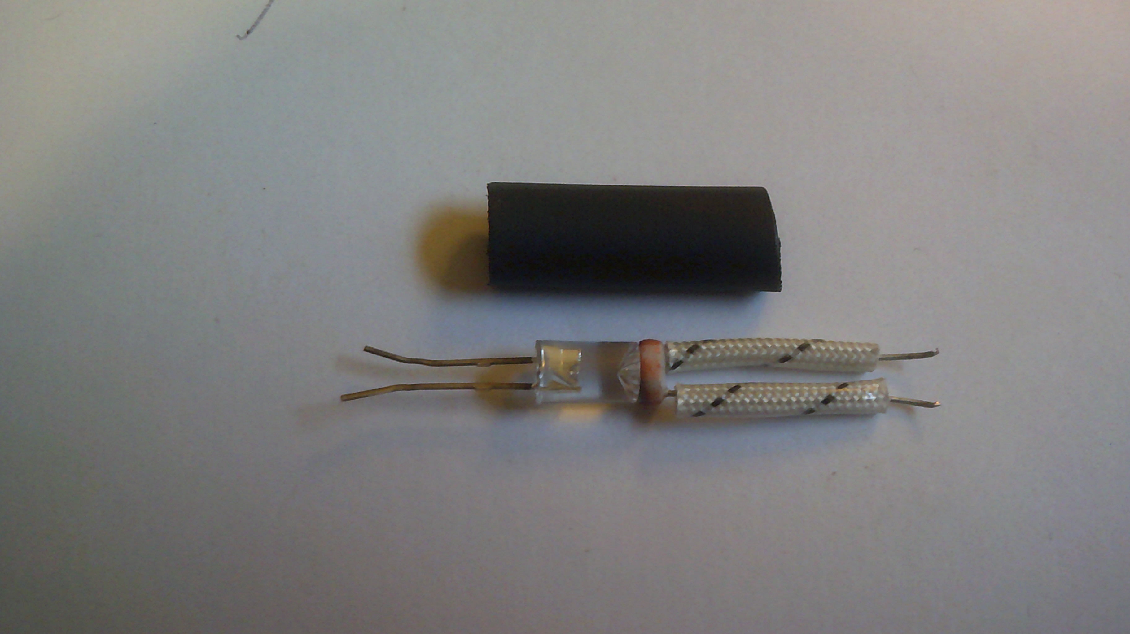
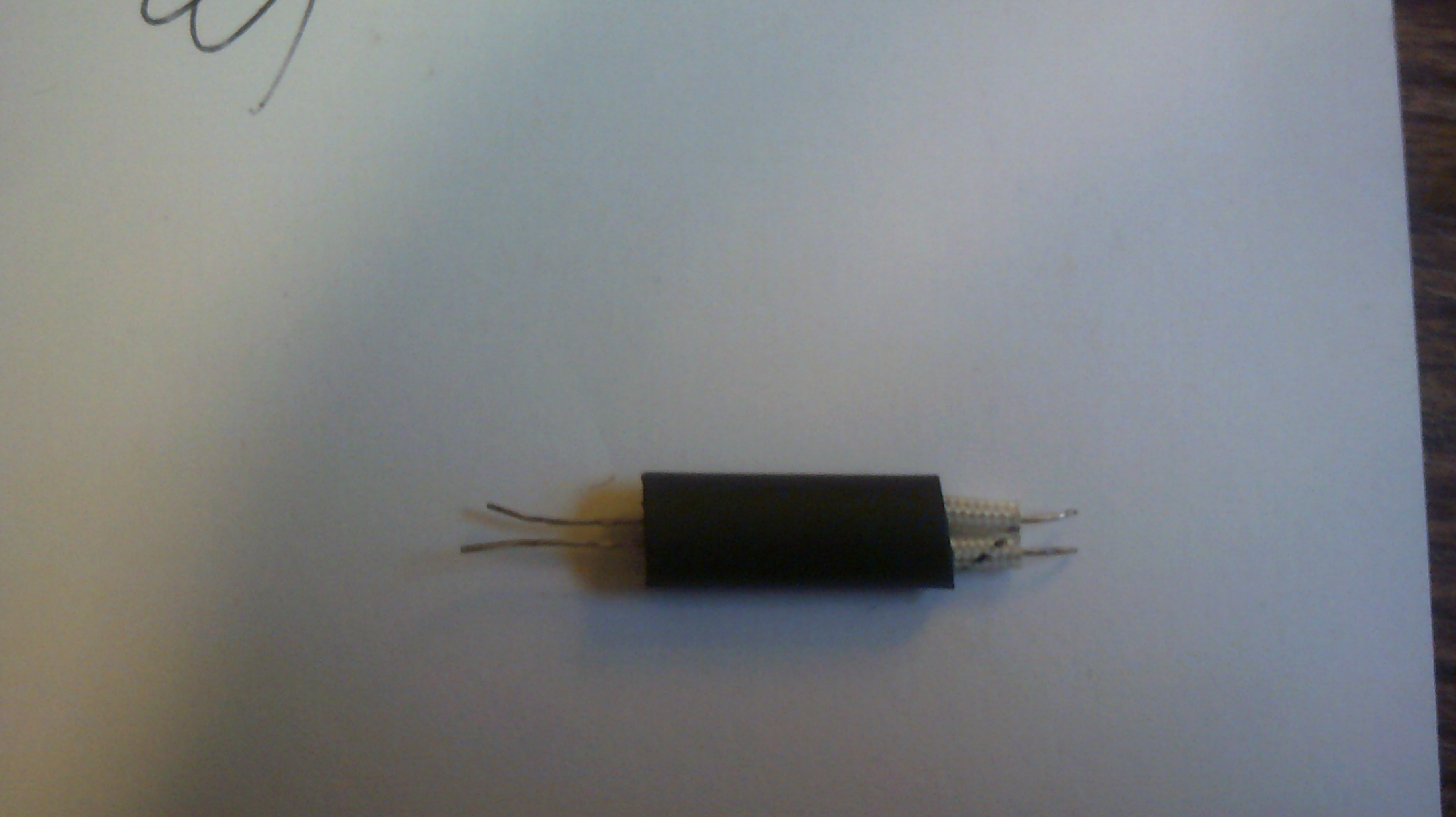
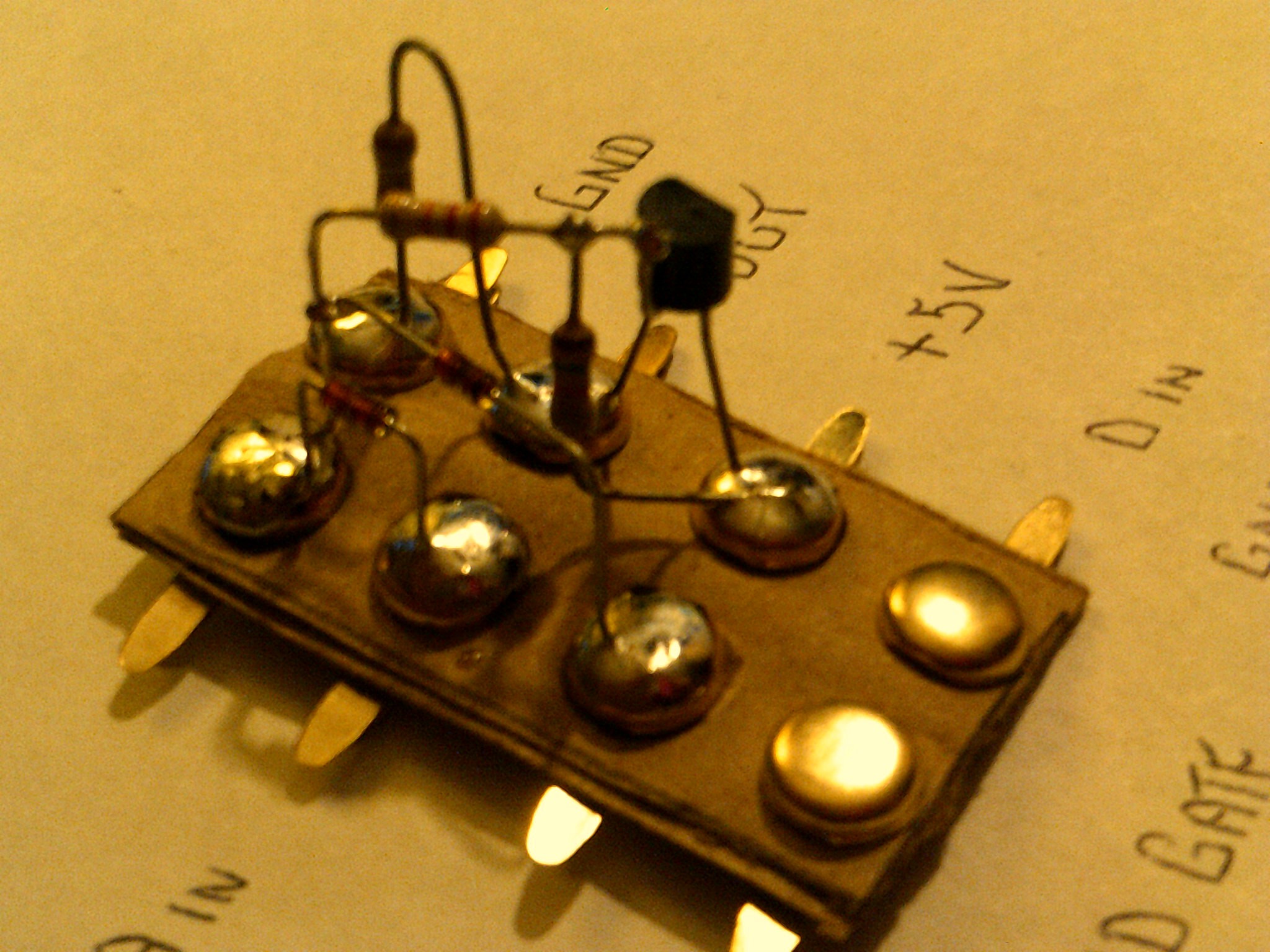
Replaced the 555 IC with a astable circuit.
2's complement works well for counting down.
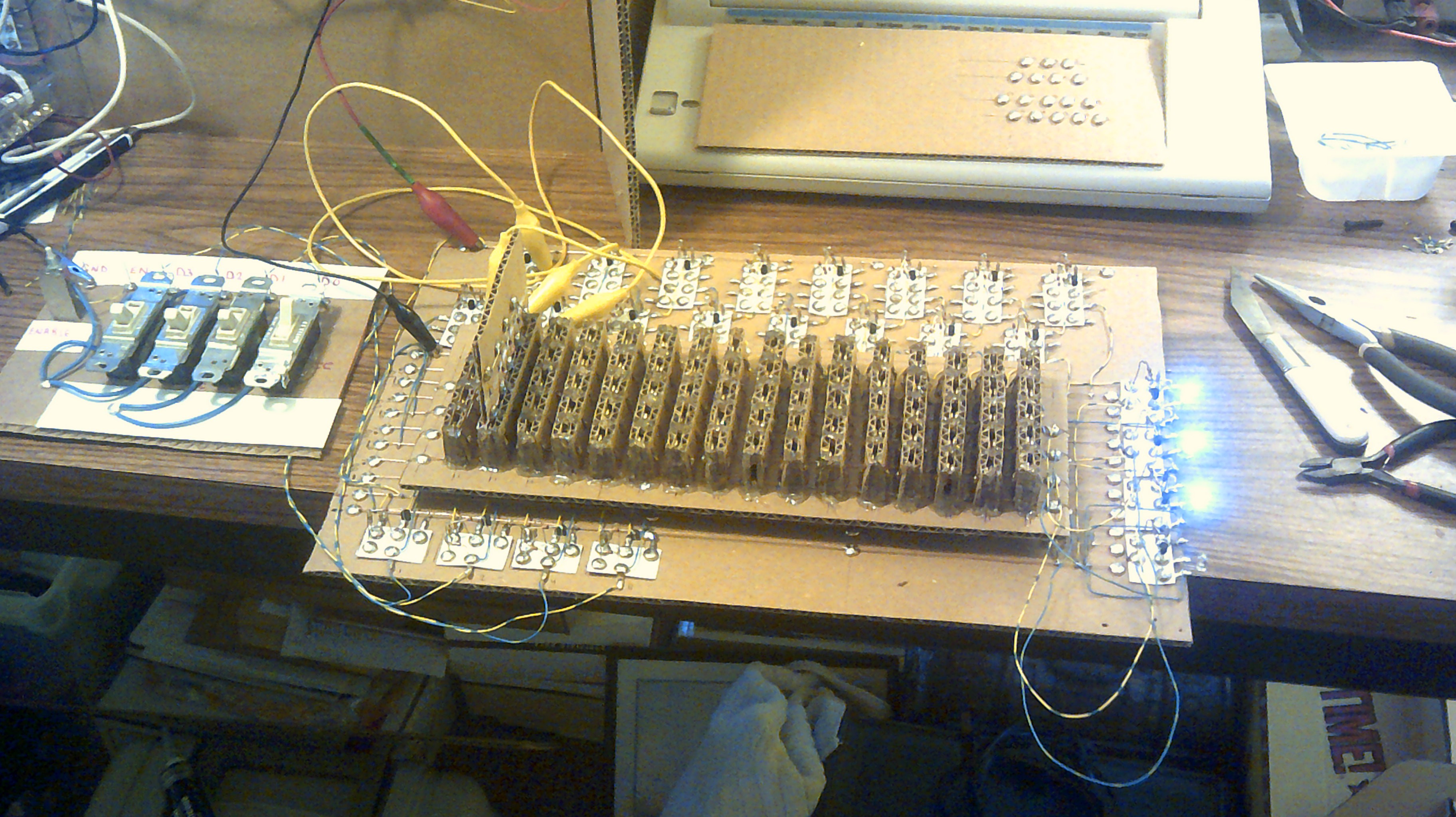
October 19, 2017 - Power usage for IO at about 1.5 watts / 5 volts
October 12, 2017 - IO's theme song. Pink Floyd - Wearing the Inside Out
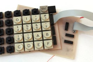
September 24, 2017 - IO has a new 7 segment display.
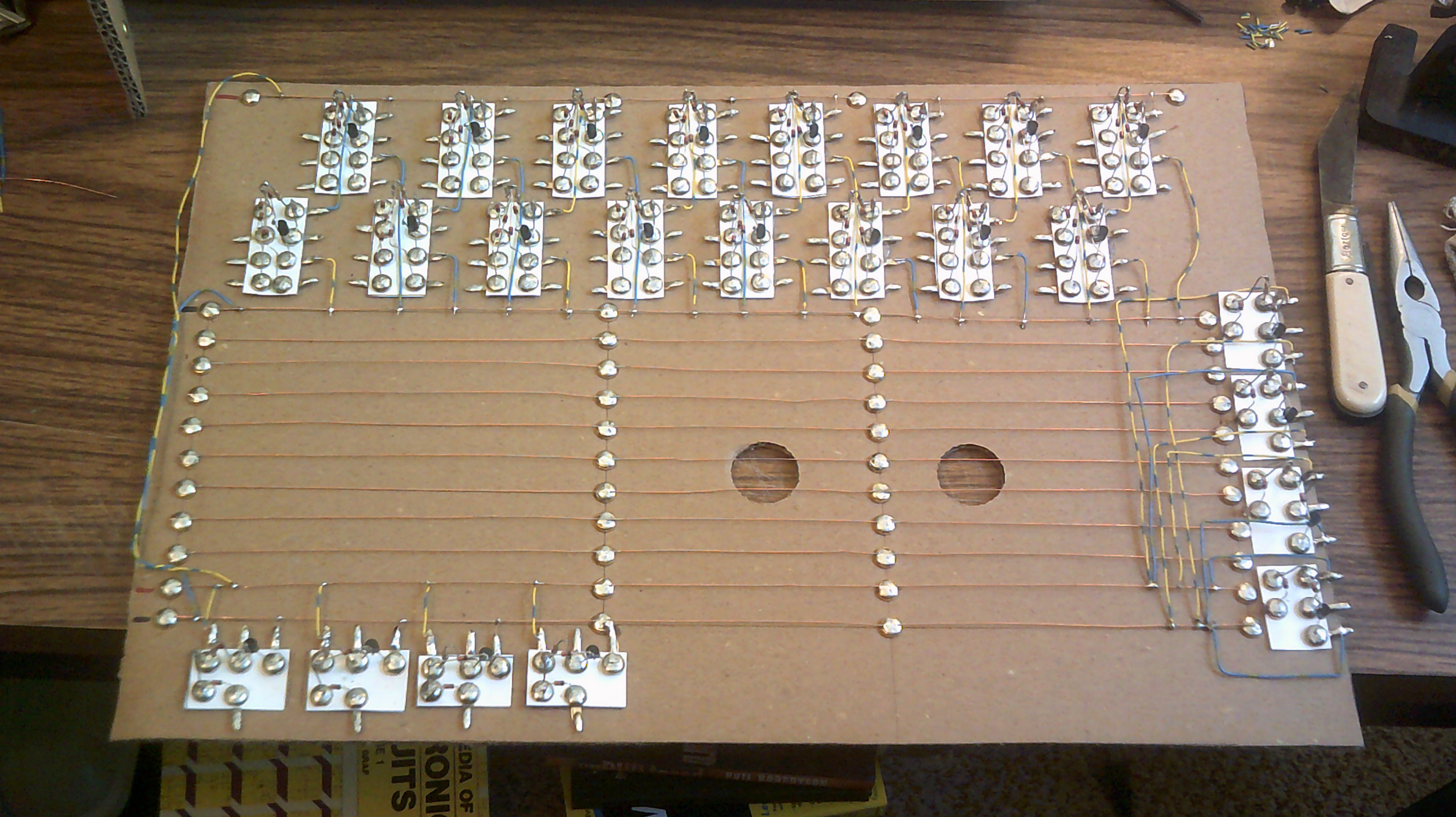
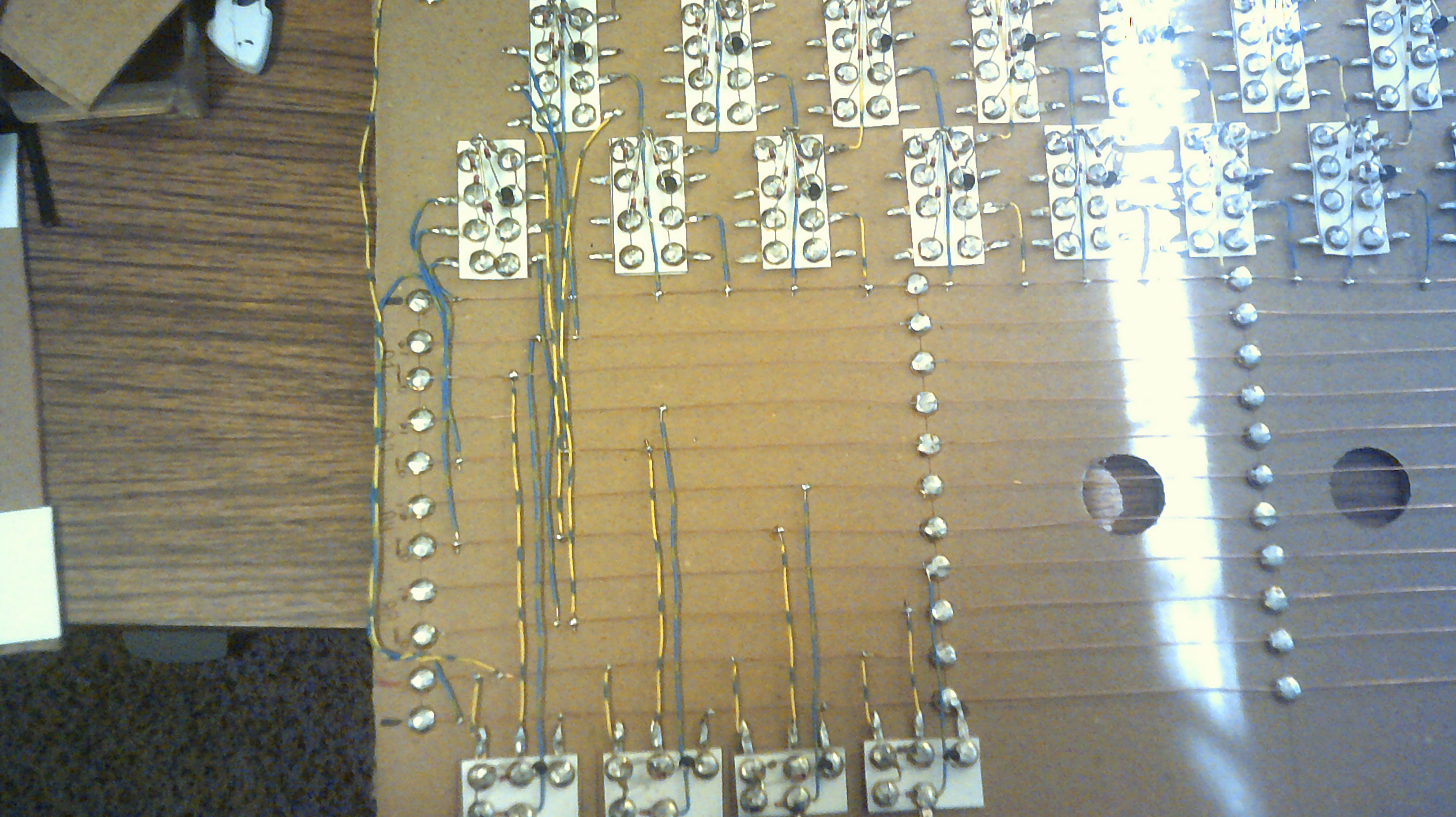
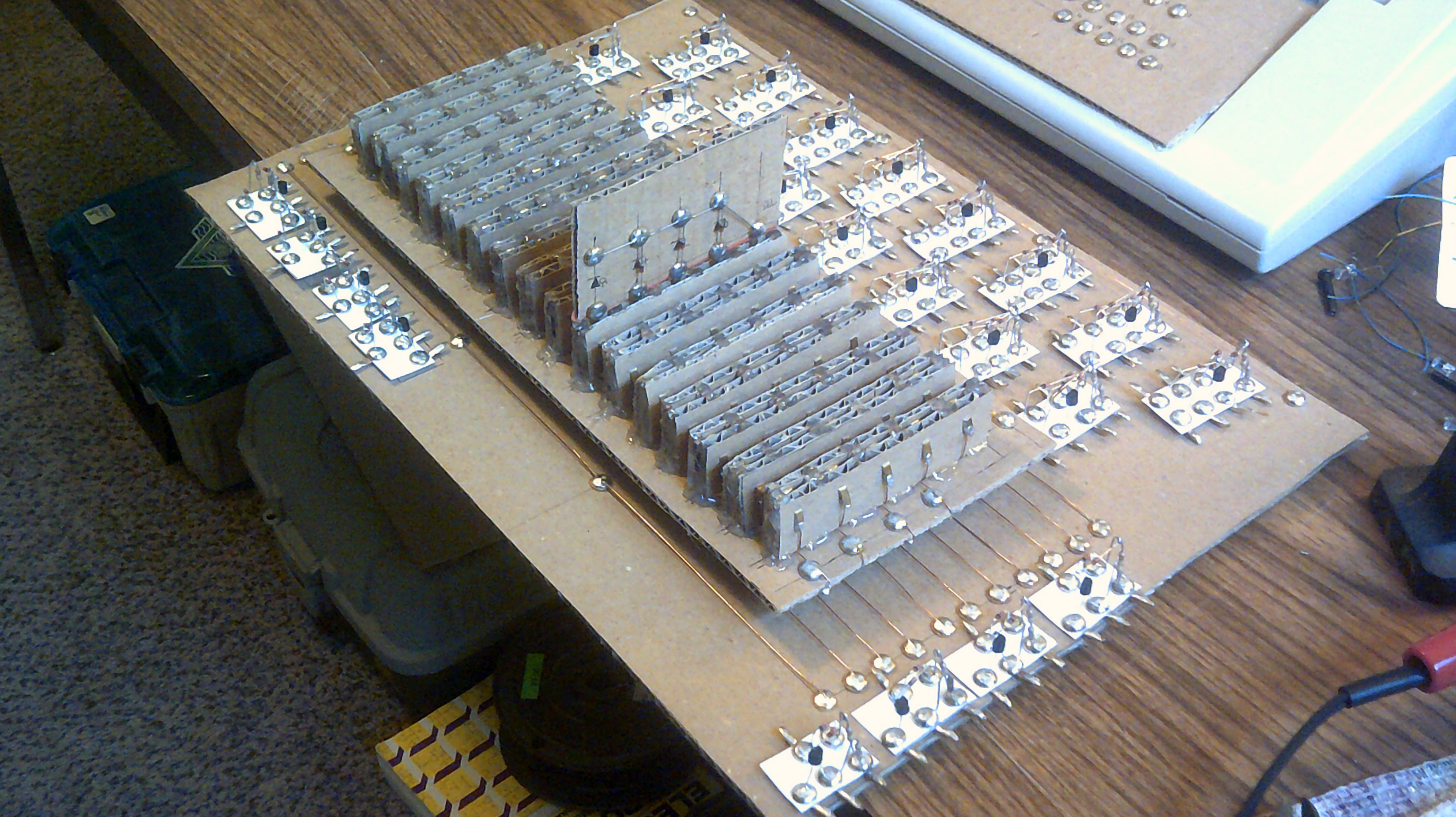
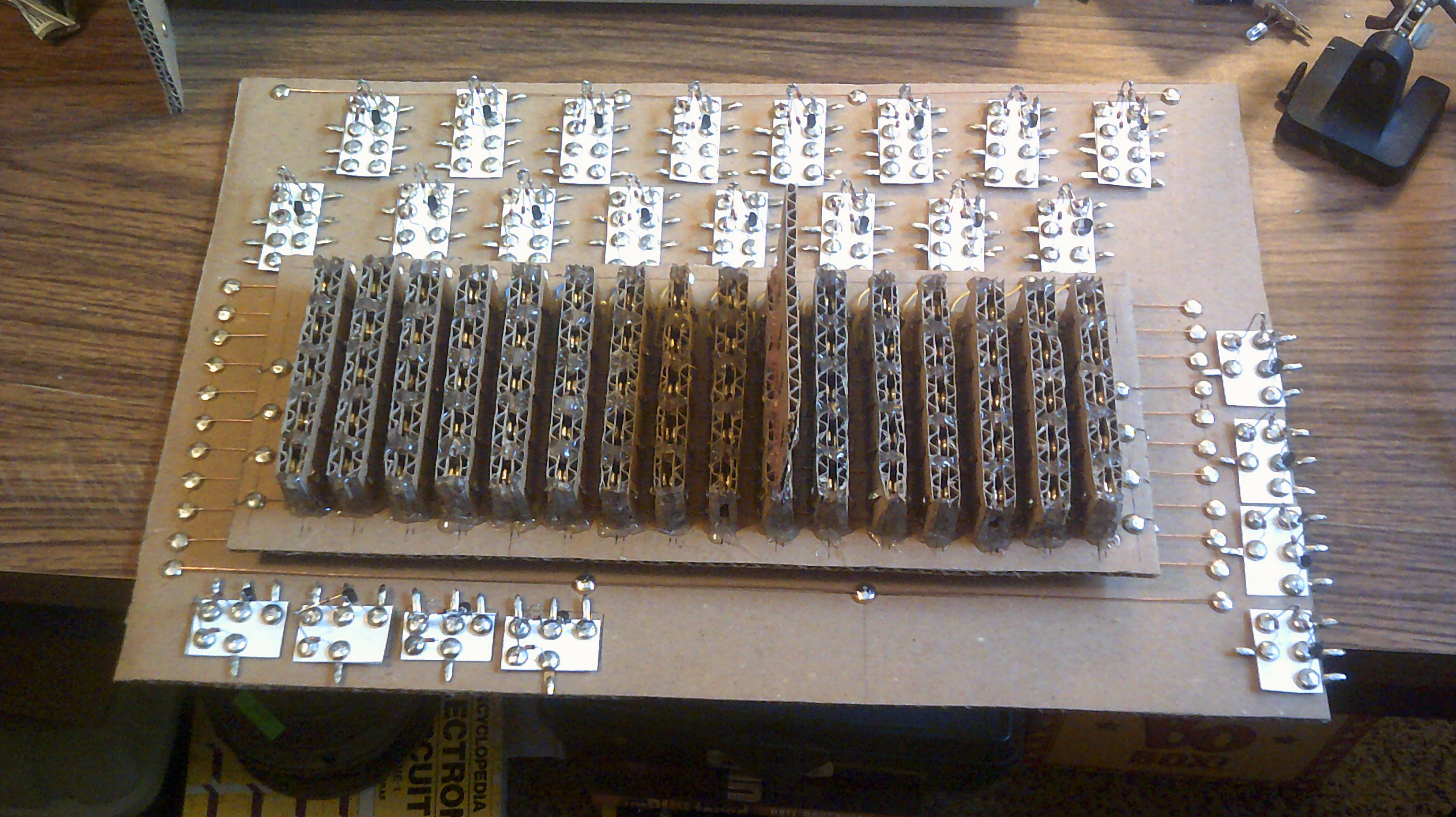
August 27, 2017 - Update, All the current sections of IO are working together.
HACKADAY Wheels, Wings and Walkers 2017 contest entry.
Cardboard computer video update 1
Cardboard computer video update 2
Cardboard computer video update 3
IO - The Cardboard Computer update 4


 Yann Guidon / YGDES
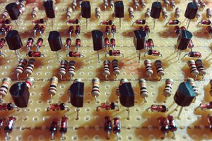
 matseng
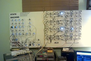
 Eric Ljungquist
How can I never seen this project of yours before? IO is absolutely amazing! From the concept of its parts , its assembly, and the hypnotic blinking of its leds! I bow in respect!