 ventosus
Project Overview
Goal
To design and build the more most open, expressive and responsive wind controller out there with an open source hardware/software toolchain, no more and no less.
System Design

Project Video
The voice may sound a bit funny as we had to speed up the video by 1/3 to get under the 2min prerequisite.
Openness
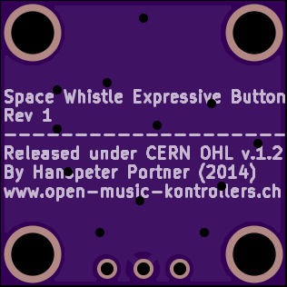
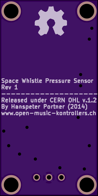
All project documentation (e.g. PCB layout, CAD files AND this very page) is released under CERN OHL v1.2.
http://www.ohwr.org/projects/cernohl/wiki
All project code (e.g. device firmware and host software) is released under a zlib/libpng license.
http://opensource.org/licenses/zlib-license.php
All project media (e.g. sound samples) are released under a cc-by-sa 4.0 license.
http://creativecommons.org/licenses/by-sa/4.0/
Expressiveness
We do not want to build yet another 'press a key and some sound is generated device'. This is just plain boring.
We are interested in an expressive play. So on/off states are a no-go for us, we need continuous dimensions. We want continuous respiratory pressure sensing and continuous push buttons.
We want to come up with a simple design for a linear push button with a continuous analog output based on linear hall effect sensors (e-valve). The ones one can buy are way too expensive and do not offer the action length we would desire.
Connectivity
Communication will not be based on serial or USB, but instead build on networking (UDP/TCP) which will be the future of all digital audio and control signals, we are pretty sure about that.
The device is synchronized to the host (running the soft synth) via precision time protocol (PTPv2). The device is plug'n'play capable via Zeroconf mechanisms (IPv4ll, mDNS, DNS-SD).
The synthesizer thus needs not be located near the device, one needs only network access to play.
Responsiveness
From analog sensor sampling to digital signal dispatch at the network controller in less than 1ms. The device update rate is at least 2kHz.
Future Orientation
We do not like MIDI, its ancient, really. We prefer Open Sound Control (OSC) instead.
https://en.wikipedia.org/wiki/Open_Sound_Control
MIDI is just too static and people are forced into a specific scheme on how to think about what a musical event is (or should be). OSC is much more adaptable to novel and unthought ways of musical expression.
OSC is mainly sent via UDP/TCP and it supports floats, which suits us well.
The output is highly resolved in time which makes it prone to network jitter.OSC bundles can be timestamped, together with PTPv2 we thus get rid of most of the introduced network jitter, something that is not possible with MIDI (neither on serial nor USB).
Modular Design
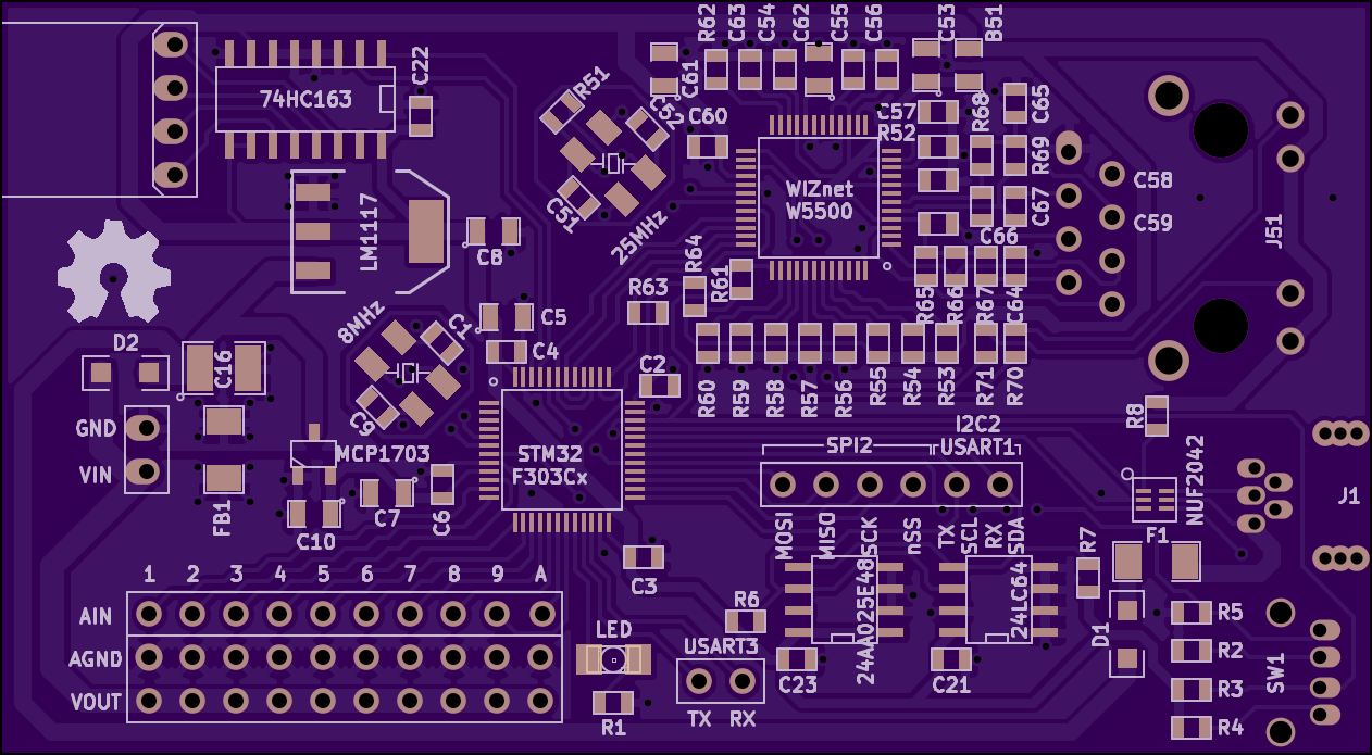
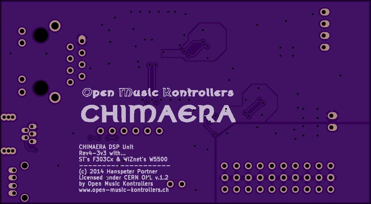
Chimaera DSP Unit
We have built a rather strange and extremely expressive touchless polyphonic ribbon controller called the Chimaera. We will use its brain, the Chimaera DSP Unit as the brain of the Space Whistle as it comes with all we need ready to use: STM32F303Cx (ARM Cortex M4 @72MHz), 10 low-noise analog inputs, 3x 12-bit ADCs, WIZnet W5500 (in-silico IPv4/UDP/TCP co-processor). The network co-processor takes most of the burden of managing a full network stack from the MCU and thus speeds up network communication a lot.
http://open-music-kontrollers.ch/chimaera
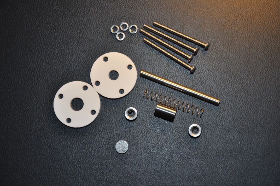
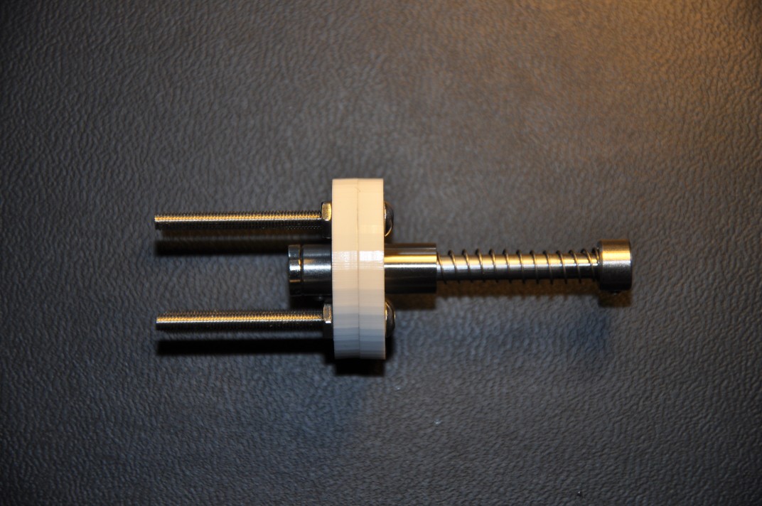
Continuous Push Button aka E(xpressive)-Valve
The e-valve is the only mechanical part (apart from the case) of the space whistle. It works like a trumpet valve but has a heigher stroke depth and an analog output. It is the heart of the expressiveness of the device. 8 of those will be arranged in a line and be actuated by the eight free fingers (thumbs are needed to stabilize the case). The analog signal is modulated by magnetic sensing. At the end of the valve rod, there sits a magnet.
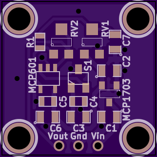
Linear Hall-Effect Sensor Breakout Board
The vicinity of the magnet is measured with a linear hall-effect sensor. We thus design a breakout board for such a sensor to be used for all 8 e-valves.
Respiratory Air Pressure Sensor Breakout Board
As the space whistle is a wind controller, it needs a means of measuring...
Read more »


 Marian Keller
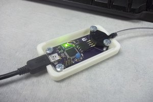
 Jason Webb
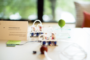
 Amitabh Shrivastava
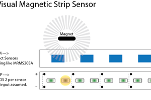
 Deezmaker