Close
0%
0%

Moti, a smart servo

Moti is a smart servo that simplifies the design of intricate robots.

Similar projects worth following
Moti is a smart servo motor that makes it easier to build robots. Imagine making a humanoid with moving limbs. You'd need a motor, sensors and a microcontroller in each joint. You'd also need to link the joints together to coordinate their actions. Moti has these features built-in. In each Moti you have a programmable microcontroller (arduino-compatible), breakout pins for attaching sensors or peripherals (eg bluetooth), and an RS485 networking port. Unlike conventional hobby servos, Moti turns continuously, so you can use it for wheels, or gear-down and still position-seek. And its the size of a standard size hobby servo, so you can keep your footprints to a minimum. We also want Moti to play well with the mobile devices and the web, so we're working on a RESTful API for developing apps. There's more to do. Check out http://www.robotstack.com

Preview:

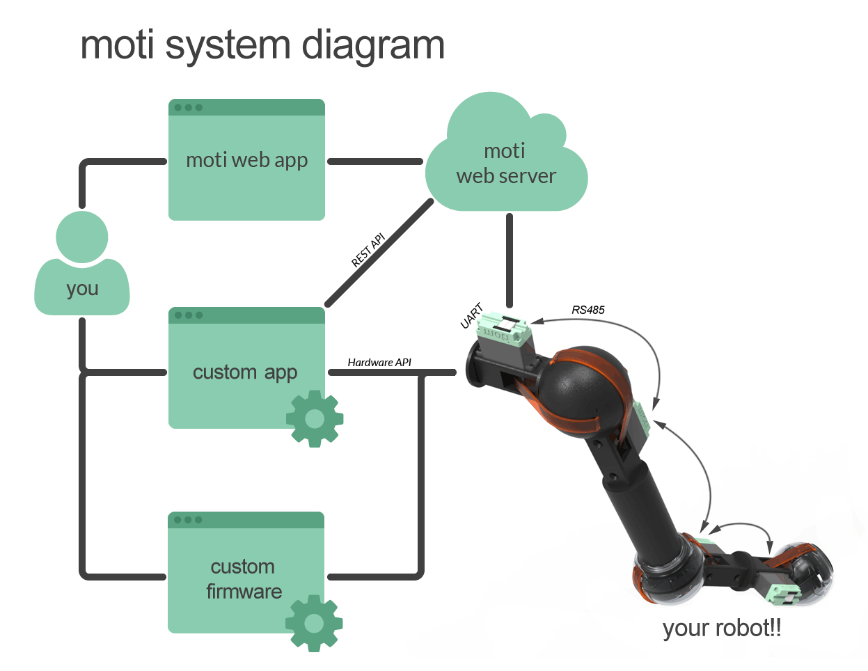
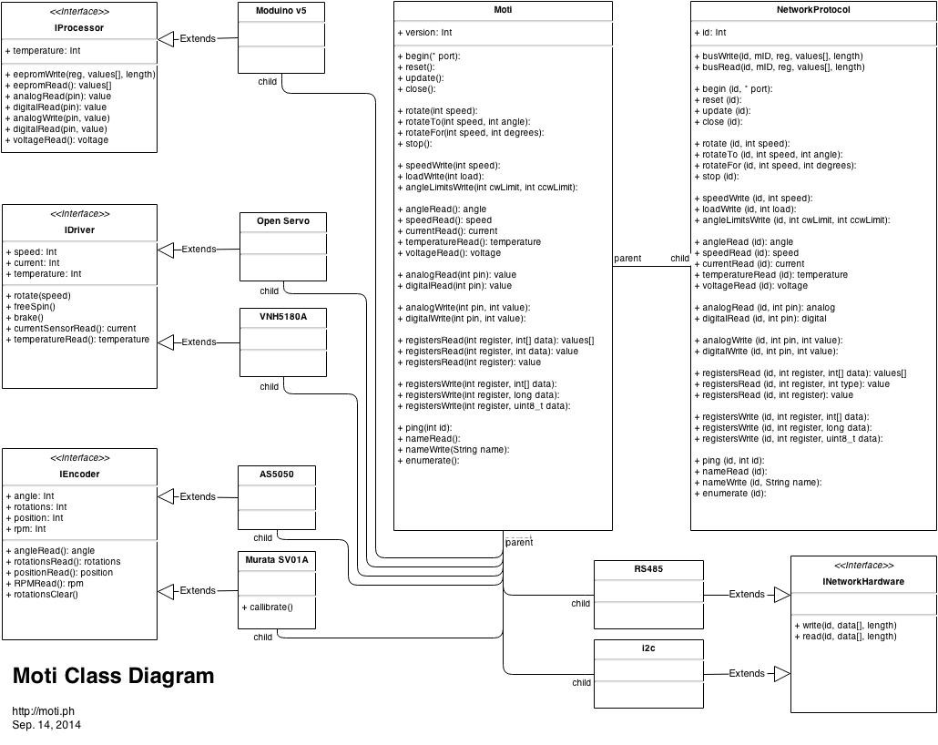
What the system diagram illustrates is that you can use our prebuilt web app to recognize, monitor, remote control & program your robot. Alternatively, you can build your own app (or use someone else's) that is customized for your application. Thirdly, you can program the motis directly to create an autonomous system.

  • 1 × ATmega328p Main Microcontroller
  • 1 × 16MHZ Crystal
  • 1 × MCP1703 250mA 5V Voltage Regulator
  • 1 × AON4420L N-Channel Mosfet for Reverse Polarity Protection
  • 1 × ISL81487IBZ RS-485 Driver

View all 20 components

  • Update - Summer 16

    Nicholas Stedman06/25/2016 at 19:01 0 comments

    I haven't posted an update in a long time, and people suspect that the project is dead. Actually, it isn't. I got busy at my job for most of 2015. But things died down a bit this year, and so I've been pushing ahead on the project, revising both the circuit and firmware.

    What's changed? Most significantly, I switched from using the atmega328 to using samd21 (ARM cortex m0+). This allowed me to resolve a bunch of nagging problems. For one, now you can program the servo directly over USB, rather than having to purchase an FTDI dongle. Secondly, I was running out of flash space and RAM on the 328, and so now there's 8 times more of each, as well as 3 x speed jump, and 32 bit instruction. Thirdly, because of the performance gains Moti can now effectively make use of an RTOS to schedule events, which makes it easier to program because many tasks automatically happen in the background. Fourthly, The magnetic encoder has also been redesigned so that board is integrated into a case. I hope to sell these soon enough as their own thing for anyone looking for 360 degree sensing.

    In the following video I go over these topics, plus demonstrate some of the performance characteristics of project. Let me know your thoughts.


  • Working through some basic motor movements

    Nicholas Stedman12/23/2014 at 04:08 0 comments

    Recently, I've been working on basic motions with Moti; things like shooting over distances, stepping, and braking. This started with comparing different types of braking: regenerative, dynamic, locked anti-phase, and even coasting to see which would stop the motor faster. Regenerative and dynamic braking were pretty much the same, and the best performing. When initiated at full speed, it takes about 15º to come to a stop. Locked anti-phase braking didn't perform well, though I'm sure it could be done better. However it generates an audible buzz at the 500Hz PWM frequency I'm using, and I couldn't stand it...so I quickly moved on. And of course coasting was the worst and was used as a control. So for the moment I'm using dynamic and regenerative braking. This website was helpful for understanding the differences between each.

    Before jumping into stepping, I wanted to see how an RC servo controls it's motor, and here I'm talking specifically about the output from the H-Bridge, so I spent some time probing it with my scope. I've uploaded a playlist of these explorations. The TL;DR of the matter is that this was highly useful. Not only did I learn how an RC servo steps, but also how it shoots and decelerates when approaching its destination. I was then able to whip up a step function that produces what appears to be both finely grained, and repeatable steps. I dabbled with shooting, but don't have anything conclusive to report about that yet.

  • Back to Work

    Nicholas Stedman11/30/2014 at 19:49 4 comments

    There hasn't been much progress on Moti for a couple of months now as I was busy with teaching and another project. Now that those things are wrapping up, I'm looking forward to getting back to it.

    A couple of questions for you. If you had to choose, would you prefer:

    1) a few breakout pins and a smaller servo,

    2) more breakout pins and a larger servo,

    3) more breakout pins that are smaller-pitch (eg. 1.27mm or 2mm instead of the commonly used 2.54mm)?

    Lastly, congrats to SatNOGS on winning the Hackaday Prize. It's an awesome project, as were all the finalists.

  • Moti v0.3 Bring-Up

    Nicholas Stedman10/14/2014 at 04:28 0 comments

    I spent much of the day getting the driver-level facilities working at their most basic. I've heard this described as bring-up, though it's the first time I've used the term, so I could be misusing it. Anyways, it was a great day, as a number of features were tested, and all worked. Thank god for using monolithic ICs instead of custom designed circuitry. It works just as specified in the documentation. Here's a playlist of a bunch of videos showing what was done.

    http://www.youtube.com/playlist?list=PLGputUCrELcBbJ8MHORK8IlhqORT-YfaO

  • Super Brief Documentation

    Nicholas Stedman10/08/2014 at 04:31 0 comments

    Moti Firmware API Documentation The Super Brief Version

    Here's synopses of the API methods provided for using Moti in the Arduino environment. Once I actually finish coding the methods I'll post more complete documentation...but this gives you the idea.

    begin(SerialPort)
    - initializes a moti with stored settings, and uses the provided Serial port for communicating over network.

    reset()
    - reset to default settings.

    update()
    - force motor update critical processes including checking for network messages, reading encoder, and changing motion as necessary.

    close()
    - shut down the motor.

    rotate(int speed)
    - Keep on going at the given speed

    rotateTo(int speed, int angle)
    - Goto a specific angle at the given speed

    rotateFor(int speed, int degrees)
    - Turn for the given number degrees relative to the current position.

    stop()
    - Stop moving and hold position.

    freeSpin()
    - Cut power to motor. Will rotate under external load.

    speedWrite(int speed)
    - Set the speed...affects any motion in progress.

    loadWrite(int load)
    - Set the stall torque of the motor.

    angleLimitsWrite(int cwLimit, int ccwLimit)
    - Set the angle limits. Limits motion between the specified limits.

    angleRead()
    - reads the encoder, and returns angle as int.

    speedRead()
    - calculates and returns the rotations per minute as int.

    currentRead()
    - reads the current sensor, and returns current measurement as int.

    temperatureRead()
    - reads the temperature sensor, and returns temperature as int.

    voltageRead()
    - reads the voltage sensor, and returns voltage as int.

    analogRead(int pin)
    - reads ADC value of the specified A2D pin, and returns the raw value as int.

    digitalRead(int pin)
    - reads the binary state of specified pin, and returns the state as int.

    analogWrite(int pin, int value)
    - writes a PWM value to a PWM pin.

    digitalWrite(int pin, int value)
    - writes a binary value to a pin.

    registersRead(int register, byte data[], int length)
    - reads a block of moti registers into the provided array.

    registersRead(int register, int data)
    - reads two consecutive 8-bit registers, and returns them as a single int.

    registersRead(byte register)
    - reads and returns a single register as a byte

    registersWrite(int register, byte data[], int length)
    - writes a byte array to a block of moti registers.

    registersWrite(int register, int data)
    - writes each half of an int to two consecutive moti registers.

    registersWrite(int register, byte data)
    - writes a byte to a moti register.

    nameRead()
    - reads and returns an 8 char array used to store a user-designated label for the moti.

    nameWrite(char name[])
    - writes 8 chars of the given array to a block of moti registers. Meant to store a user-designated label for the moti.

    enumerate()
    - query all available motis on the network. They will each reply with their unique ID.

    ping(int id)
    - check for the specified motor on the network.

    messageAvailable()
    - checks the network port for new message and returns the length of the message as an int, or 0 if no message.

    messageRead(byte data[])
    - checks the network port for new message and saves it to provided array.

    messageParse(byte data[], int length)
    - decipher the message, and return a struct containing the ID of the Moti, the command, the parameters, the length of the message, and other parameters if available.

    messageWrite(struct message)
    - packetize and send a message over the network containing the IDs of both sender and receiver, the command, the parameters, the length of the message, and other parameters if available.

    ---

    N.B. int here means uint16_t, and byte means uint8_t.

    N.B. Methods can be overloaded by providing an ID (int) as the last parameter, or a name (char[8]), in which case this Moti will trigger the operation to occur on the designated Moti in the network if available. The only exceptions are begin(), enumerate() and ping(). Overloaded methods are not shown here for brevity.

  • update on update( )

    Nicholas Stedman10/07/2014 at 03:31 0 comments

    I've been mulling over how to make Moti's programming interface flexible, like Arduino, while regularly running a number of required processes, including reading the position from the encoder, checking for network messages, and affecting the motor as necessary.

    Option 1: Update Moti in the main loop.
    Up until now, I've been using an update() method that executes all the required processes. This is called from the main loop at regular intervals (look at the Arduino screenshot here). It works fine if you are using the default firmware, as you probably are if controlling from another device (eg. mobile app, computer), but if you want to modify the firmware, say to create an autonomous robot then the scheme's shortcomings start to show. In particular, it forces the user to deal with scheduling the updates, which is a hassle. The problem is that if the motor is rotating to a position and it is too long between updates (and thereby reading encoder steps), we risk rotating right past the destination, a potentially catastrophic failure.

    How frequent does Moti need to update? It depends! The period between updates can be no longer than the time it takes to move one encoder step. Our current hardware peaks at about 80rpm, which means it takes ~1333 ms per 360º. Since the encoder ADC is 10-bit, that's 1333/1024 = ~1.3 ms per step. That's often! There's not much room for other processes to happen in the main loop when we have to update so frequently…certainly no millisecond delays. Keep in mind that this is a worst case scenario. You'd have to be using specific methods (rotateTo() or rotateFor()) at the fastest speed to require updating so often, which suggests that the frequency could be reduced when the motor is further from it's destination, and/or is moving at a slower speed.

    Returning to the problem at hand, in this scenario, the user is forced to work out these timing issues and ensure that update() is called as often as necessary. But do they want to do that? I'm betting No. Imagine trying to write a program while making sure that a process executes every few milliseconds, every other line might be update()! There may be scenarios where a user needs to manually update, but as a default I think it would be better to bury it in the background.


    Option 2: Update Moti in the background.
    You may have already figured out that we can use interrupts to schedule updates. A timer interrupt is set to go off in time to execute the update() before the deadline. This is great, because if the update() runs in the background, a user can program the main loop normally.

    But this approach has it's own issues. As a rule ISRs are supposed to be kept as short as possible, but how long is too long? Moti's update() currently takes approximately 0.5ms. Is that too long for a single ISR? I think so, as it may interfere with time sensitive operations in the main loop. A common strategy to avoid long interrupts is to set flags in the ISR and then deal with them back in the main loop. However, this puts us in the same predicament as scenario 1, where the user is forced to deal with update() in a timely manner.

    Better, would be to reduce update() to a minimum so that it can be handled in the ISR. Right away, I think we can cut the routine in half through basic optimization. Also, a major chunk of that time is consumed by reading the encoder. Instead of waiting, we can monitor the conversion with another interrupt. Now we have:

    1) run main loop operations until timer interrupts
    2) timer ISR: start ADC encoder reading with interrupt
    3) run main loop operations until ADC interrupts
    4) ADC ISR: check for new messages from network, change motor state if necessary

    By peeling off the analog conversion from other processes, I think we can shave another 0.125 ms off the ISR, leaving us with an ISR of 0.125ms. I think that's worth a try, and I'll follow up in the future after giving it a go. I may also partition the network checks off into their own timer-based...

    Read more »

  • Product Drawings

    Nicholas Stedman09/29/2014 at 01:55 2 comments

    Here's a rendering of a fully assembled moti:

    and here's an exploded view:

    The exploded view shows how the product assembles together. You can see how the magnetic spindle has a shaft that fits in the output gear. It's the same size as the potentiometer shaft used used in conventional servos. The spindle spins right above the magnetic encoder IC which is on the bottom side of the pcb.  The spindle maintains it's rotation axis by fitting a nipple (?) into a registration hole in the pcb. The design has changed a little since this model was generated but it's still quite close.

    Drawings were done in Solidworks. The same designs are used to generate .stl files that have been used to 3d print the case bottom and the housing for the magnetic spindle.

  • More Diagrams

    Nicholas Stedman09/25/2014 at 23:43 0 comments

    I've been working on the firmware without actually doing a whole lot of coding. I'm kind of circling from the outside to suss it out without rushing in. My ideal is to improve the quality and so I'm looking into best, or at least better practices. Recently, I've been reading Making Embedded Systems. I recognize the risk of brown-nosing here as it's written by one of the judges, but it's also on my mind right now. See, I have no formal training in engineering, and in order to improve I need to see things in practice. This book contains some really nice design patterns for better organizing firmware, and shows examples of how to implement them. The book I discussed previously, turned out to be a bit too theoretical, which is fine if you have the training but left me wondering "ok, but how?"

    Anyways, some of what I've been working on includes the following diagrams. For the record, these kinds of diagrams are not discussed in the book. The first two are use cases. This one represents a sequence of actions, and invoked methods that occur when someone remote controls a Moti-enabled robot:

    The second shows a sequence of events that occur when someone is recording a sequence of manual manipulations of a Moti enabled robot, and then plays them back:

    These diagrams are not exhaustive. There's more steps involved. However it's enough to suggest that the model for breaking code apart could work. Okay, so having done the use cases I went on to make a UML class diagram. Now, I can imagine that many think it's a waste of time, but for me I wanted to try using one of the tools available to clarify each class and their relationship before writing them. 

    One thing I realized making the class diagram was that I could decouple the network hardware from the network protocol. Maybe that in itself made it worthwhile. 

    Anyways, it's all still new to me so If you see anything wrong with the diagrams please let me know. It's been a fun exercise and quite the opposite of how I usually dive right in...I kind of feel like George Costanza:

    By the way, if you want to use the same tools I did, try draw.io for the class diagrams, and the very cool web sequence diagrams for you guessed it, the sequence diagrams.

  • New Magnetic Encoder Available

    Nicholas Stedman09/25/2014 at 22:16 0 comments

    I just discovered that Austria Microsystems (AMS), my preferred source for magnetic encoders have recently released the AS5600. It looks very promising compared to the AS5050A I have been using. It costs $1.65 (per 1000) versus $2.98 for the 5050, and has 12 bit resolution versus the 10 bit of the 5050. It also requires fewer external components, and can run at 3 or 5V levels. This means I can eliminate a voltage regulator, a level shifter, and several passives. Switching to the 5600 should reduce the BOM cost by at least a couple of dollars. It even uses I2C or Analog out, instead of SPI + interrupt line, so even fewer IO pins will be consumed. 

    At any rate, I will continue developing with the 5050 for now, and later swap to this newer chip. In theory, it shouldn't be too complicated to switch from one to the other, because Moti has a modular design where the encoder is broken out on it's own board.

    In fact, the flip side of the Moti encoder board was designed to the AS5161, which turned out is not appropriate for Moti. However, its SOIC-8 package, and the layout of the power pins and analog out pin are the same as the 5600, so I may be able to start working with it right away!

    Hmmm, it would be pretty awesome if I can use just an A2D pin to capture position, because then the encoder board could perhaps be swapped for a pot if the user wanted to try Moti circuits in regular servo motors.

  • growing pains

    Nicholas Stedman09/06/2014 at 22:50 0 comments

    Once upon a time, I said this about having written the firmware as one huge file: "While it wasn’t as bad as you’d think, it’s clearly not ideal." This is the understatement of the year. It is as bad as you'd think. Disentangling, and refactoring into different libraries is slow, painful and messy! But at least it's getting done. I'm also looking forward to writing fresh code for the new hardware. 

    On a related topic, in my haste to get the boards done, I overlooked an issue. The Micro's UART joins to the RS485 bus for daisy chaining. But this is also the port by which the Micro is programmed (and potentially communicated with while running) by another UART (eg. FTDI), so potentially two TX lines are tied to one RX (the micro's). Now imagine one goes LOW during transmission, the other is still HIGH, and so not only will the transmission fail, but the two competing lines may short out if they are unprotected. The remedy (working so far) is to add a couple of shottky diodes to prevent either of the TX lines from pulling the micro's RX HIGH, which is instead provided by a pull-up resistor. It's working, as I've been able to bootload the firmware onto the Processor board...so hooray for that. However it looks like at least another board revision is in order.


    In other good news, I received a Hackaday Prize T-shirt for Moti having done well in one of the open votes rounds. So thanks!

View all 14 project logs

Enjoy this project?

Share

Discussions

VASILIS VORRIAS wrote 02/07/2022 at 09:04 point

Hi @Nicholas Stedman What is the status of your project? . The continues motion is grate. I am really interesting on building it and plug  it into our M0CUBE controller. Our new GRBLHAL Universal controller have RS485 on board (among others EtherNET, CANbus).
https://hackaday.io/project/171770-m10cube/log/202098-m10cube-pico-cnc
So it will be nice to start experimenting in the robotics field among others. I subscribed for a newsletter but project looks dead. Pity if that is so. It has grate potentials. One can be substituting the expensive CPU you are using with R2040.
So please I like very much to help  in any way.

  Are you sure? yes | no

Luis wrote 06/09/2022 at 15:53 point

Maybe you are interested in my project.

It is a similar concept.

LibreServo | Hackaday.io

  Are you sure? yes | no

crener wrote 03/04/2020 at 21:24 point

Hey, Is this still a thing.... I want to mess around with one... :)

Hope you get the chance to finish it 

  Are you sure? yes | no

Kinglis wrote 05/07/2018 at 14:27 point

Happy 2018! Just signed up for your newsletter in case this project is still alive. Any Progress?

  Are you sure? yes | no

Nicholas Stedman wrote 10/26/2018 at 14:54 point

HI Kinglis,

Thanks for singing up. Yes, I'm still working on Moti as a side project. At the moment, I'm building a robot to test  the features...still a decent amount of work to do there. If it works as intended then I'll release some version of the project after.

  Are you sure? yes | no

Manfred wrote 06/18/2016 at 14:58 point

Hi,

I take it from the lack of updates that this project has been shelved? A pity as it sounded very interesting.

  Are you sure? yes | no

Nicholas Stedman wrote 06/18/2016 at 15:08 point

Hi Manfred, Actually I've been working on it a lot. I just stopped posting updates because frankly I was embarrassed about the never-ending development!! I'll post at least one update in the next week, as there are some significant changes.

  Are you sure? yes | no

Petr Švarc wrote 01/02/2016 at 11:22 point

Where can I buy ? :-) It is perfect for robots...

  Are you sure? yes | no

Nicholas Stedman wrote 01/02/2016 at 17:05 point

Hi Petr,

Not ready yet. I'll let you know as soon as it is.

  Are you sure? yes | no

Petr Švarc wrote 01/03/2016 at 16:55 point

I'll be patient :-).

  Are you sure? yes | no

Mike Maluk wrote 10/28/2015 at 00:37 point

Very awesome project! I haven't read too in depth, so I may have missed it, but any plans to add battery power to each servo? This would allow the servo to be completely independent of any wiring, and make it really simple. I'd love to have something like this on R/C aircraft, would really ease setup!

  Are you sure? yes | no

Nicholas Stedman wrote 11/02/2015 at 15:33 point

Thanks Mike. I haven't planned for a battery pack, but it wouldn't be too difficult (famous last words) to make a 3d printed battery pack that could be mounted to the back of the servo supplying power through the power pins. For now though, I am just trying to get it done!

  Are you sure? yes | no

Whjas Huanh wrote 05/12/2015 at 11:12 point

Nice project ! If you have any PCB manufacture need, please visit PCBWay, free universal boards as gift.

  Are you sure? yes | no

VPugliese323 wrote 09/29/2014 at 03:07 point
I have one question not addressed by your project logs. Are you planning on addressing security concerns; as a networked device, do you have any plans to make your device more secure that I gather it presently is? To be specific, after reading your project logs, it seems as if anyone could (in theory) SSH over to the server controlling the motors and control them. For an industrial robotics project, that would be extremely dangerous. I realize that you cannot have perfect security with this (or any connected) technology, however I did not see any mention of how the connections are secured. I may have missed something because I was reading quickly, if so then my apologies. This is an interesting project, I like it.

  Are you sure? yes | no

Nicholas Stedman wrote 09/29/2014 at 05:39 point
Thanks for the question. The short answer is that we haven't built any security features at this stage, but aim to as the project develops. We'll need help in that area. Do you have any suggestions?

  Are you sure? yes | no

VPugliese323 wrote 09/29/2014 at 11:10 point
For these kinds of things, I must admit I default to two good books on the matter that I have. http://www.amazon.com/Counter-Hack-Reloaded-Step-Step/dp/0131481045 and http://www.amazon.com/Secure-Coding-Edition-Software-Engineering/dp/0321822137

  Are you sure? yes | no

PointyOintment wrote 08/11/2014 at 18:44 point
You might find this interesting: https://www.youtube.com/watch?v=_g79mOSvSsE

Be sure to check out the link in the description.

  Are you sure? yes | no

Nicholas Stedman wrote 08/11/2014 at 19:50 point
Very very Cool, but the links redirect, or 404.

  Are you sure? yes | no

Jasmine Brackett wrote 08/06/2014 at 21:20 point
Hello nsted, now is the time to add a few more details to your project to give it the best chance of going through to the next round of The Hackaday Prize.

By August 20th you must have the following:
- A video. It should be less than 2 minutes long describing your project. Put it on YouTube (or Youku), and add a link to it on your project page. This is done by editing your project (edit link is at the top of your project page) and adding it as an "External Link"
- At least 4 Project Logs
- A system design document
- Links to code repositories, and remember to mention any licenses or permissions needed for your project. For example, if you are using software libraries you need to document that information.

You should also try to highlight how your project is 'Connected' and 'Open' in the details and video.

There are a couple of tutorial video's with more info here: http://hackaday.com/2014/07/26/4-minutes-to-entry/

Good luck!

  Are you sure? yes | no

flaco wrote 07/13/2014 at 12:36 point
Here's something really interesting ! :D

  Are you sure? yes | no

Robot wrote 07/10/2014 at 23:51 point
Wow. Such a worthy product; I'm sad to see that the kickstarter failed.

  Are you sure? yes | no

crener wrote 07/10/2014 at 19:02 point
Hmm, i wonder if i could put one of these in place get all the settings/timings that i need (e.g. for a hex) and then replace with a normal servo?

It should work as long as i don't use any sensors that are attached to it. I just "learn" a pattern with the smart servo and then swap it with a normal one one i have its positional informaltion captured.

Anybody think this could work?

  Are you sure? yes | no

Nicholas Stedman wrote 07/10/2014 at 21:09 point
That's an awesome idea that hasn't come up before. It should work as long as moti exceeds your max requirements in speed and torque.

  Are you sure? yes | no

Tiago wrote 07/06/2014 at 16:27 point
I really like this project, might buy a bunch if they are not too expensive. Already got a bunch of ideas in mind for them. When you say full rotation position tracking do you mean it has a range of 360 degrees, or continuous rotation with an encoder? If it is an encoder, then am I correct in assuming that they do not know their position on startup, only relative positions?

  Are you sure? yes | no

Nicholas Stedman wrote 07/06/2014 at 21:33 point
Thank you. A new development is that Moti has a 10-bit magnetic encoder with a 360º range, so the absolute position is always known. There are no mechanical obstructions limiting rotations, so it can continue rotating as long as needed, and every 360º/0º rollover is logged in a register, which you can clear when you like.

This can be used in several ways. For example, you could have it turn precisely 1001º. Or you could remote control it to go some distance, and then read back how many degrees/rotations were required to get there. You could even manually turn the motor, record the positions, and then replay the patterns.

  Are you sure? yes | no

Tiago wrote 07/06/2014 at 22:34 point
That's really cool, would be so helpful for a project I am working on at the moment :) How much will they cost, aproximately, and when will they be available?

  Are you sure? yes | no

Nicholas Stedman wrote 07/08/2014 at 16:38 point
It's still going to be a while before Moti is released. We'll probably start beta-testing the new design this fall, and hopefully have a release (at least of the boards) later this year. As for price, I'd like to keep it below $55 for a preassembled servo (and cheaper of course for just the assembled boards). I know that sounds expensive but the driver, encoder, Arduino and motor end up costing a fair bit. Actually, I'd love to hear reactions to that price?

  Are you sure? yes | no

Tiago wrote 07/08/2014 at 16:40 point
Sounds pretty cheap, actually. A 1.5 turn servo with position control will be much costier.

  Are you sure? yes | no

mandoline wrote 06/28/2014 at 13:56 point
Nice idea. Can these be RF controlled, because that would indeed be handy.
Also for robotics use a regular servo could be used as the backplate and its existing controller chip grafted onto the new board with the magnetic rotation sensor to add longevity.

  Are you sure? yes | no

Nicholas Stedman wrote 07/02/2014 at 18:31 point
We've got bluetooth and xbee already, but for other RF one could design a new shield.

  Are you sure? yes | no

regiscruzbr wrote 06/27/2014 at 01:21 point
Kick ass project...
I have an application for it on my home automation.

  Are you sure? yes | no

pajolegault wrote 06/24/2014 at 23:17 point
This is a great example of a project that makes the stuff to make the stuff.
Some development variations I could see working with this. Add a hall effect sensor and accessible positional PID so that the motor can monitor and report on its loading, be tuned, and work with a wider range of voltages.

A pickle adaptor for use as a remote and for training the embedded micro.

Slaving for systematic control. You control one servo and it can control at least three other servos. For example you could have the fast servo, have it control the ratchet directional- position locker toggle servo, and the slow geared ratchet drive high torque servo, and a weighted spring, hammer drive loading servo. Or simply use a push me pull you control between two servos so that when one servo winds in, it tells another servo to wind out.

  Are you sure? yes | no

Nicholas Stedman wrote 06/25/2014 at 00:04 point
Thanks for the feedback. Are you thinking hall effect for position, or current sensing, or something else? We've switched to a magnetic encoder for position, and current sensing is provided by the h-bridge. PID settings are open as you suggest. I hope to add more detail soon, and update the pics.

I have no idea what a pickle adapter is?! But it sounds like something awesome.

We're also switching from i2c to rs485 because of the extra distance it affords, with up to 128 nodes (at least in theory). You can customize the addressing, and program the nodes to achieve the desired network topology.

  Are you sure? yes | no

pajolegault wrote 06/25/2014 at 00:58 point
A pickle is just controls on a cable, so a wired remote. You can plug in a joystick for example. It might be jargon specific to some industries. I should have just said a wired remote.

Bluetooth would also work and no socket needed.

  Are you sure? yes | no

pajolegault wrote 06/25/2014 at 01:03 point
I was thinking of the Hall effect sensor for the motor current.

Current sensing is provided by the H-bridge or current limiting?

  Are you sure? yes | no

Nicholas Stedman wrote 06/25/2014 at 01:21 point
We're trying out the VNH5180a with built-in current sensing http://www.st.com/web/catalog/sense_power/FM1965/SC1039/PF250358
Will post how it works out.

  Are you sure? yes | no

samern wrote 06/16/2014 at 17:23 point
I have some many projects for this thing, the mind boggles. I wish I knew, I would've contributed to the Kickstarter.

  Are you sure? yes | no

technolomaniac wrote 05/02/2014 at 06:57 point
Awesome concept! Very cool to see and super interesting!

  Are you sure? yes | no

dave.m.mcdonough wrote 04/29/2014 at 15:47 point
Is this just a servo piggyback board or the complete package? Because I'm curious about the servo torque specs, or if I want to use a bigger motor..

  Are you sure? yes | no

Nicholas Stedman wrote 05/13/2014 at 18:16 point
The plan is to offer both a preassembled servo, as well as make the boards available so you can put them inside the servo motor of your choice (though they may not fit inside every case).

I don't have final specs on the on the torque of the preassembled servo, but conservatively it will be at least 11 kg*cm with metal gears. And one thing I'm looking forward to is the ability to use it with gearboxes to up the torque without having to hack the servo. (eg. https://www.sparkfun.com/products/12606).

  Are you sure? yes | no

Similar Projects

Does this project spark your interest?

Become a member to follow this project and never miss any updates