 Dan DWRobotics
As with all of my work, I am designing this to be made from the cheapest components possible. The idea is that I would be able to create a full size humanoid platform that can be purchased for under £800.
Update for 2018, New video of Mark II design:
Updated with extra video:
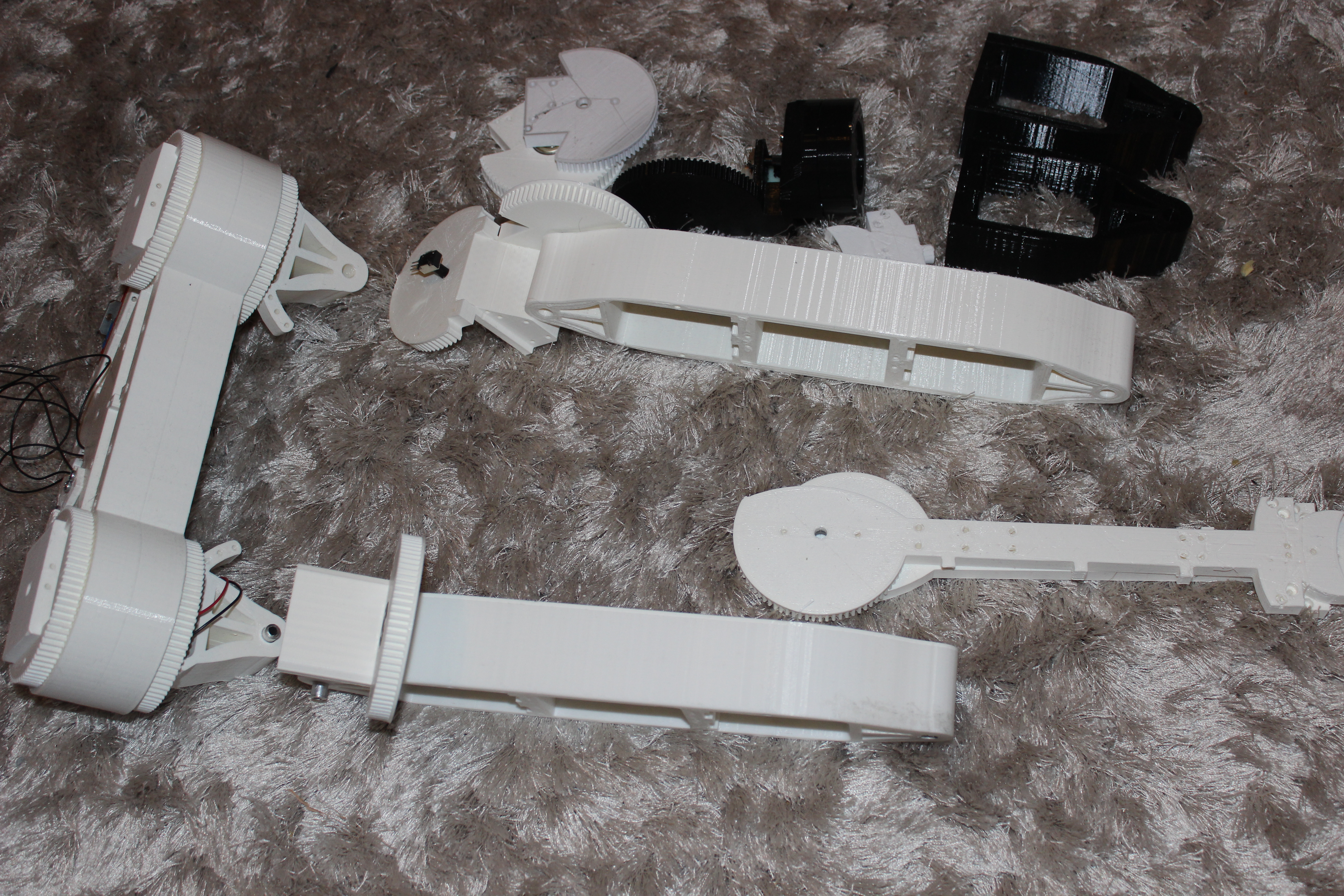
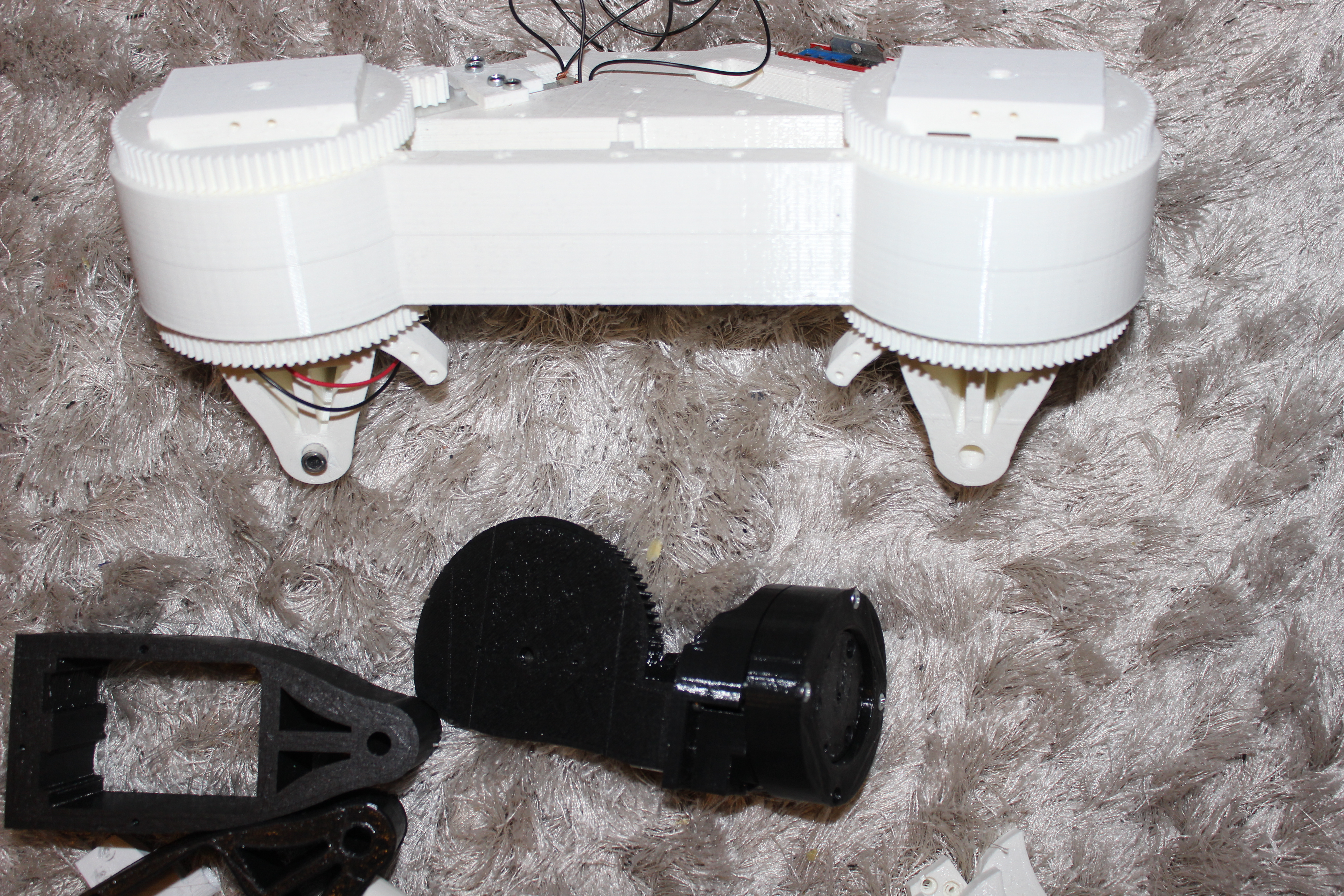
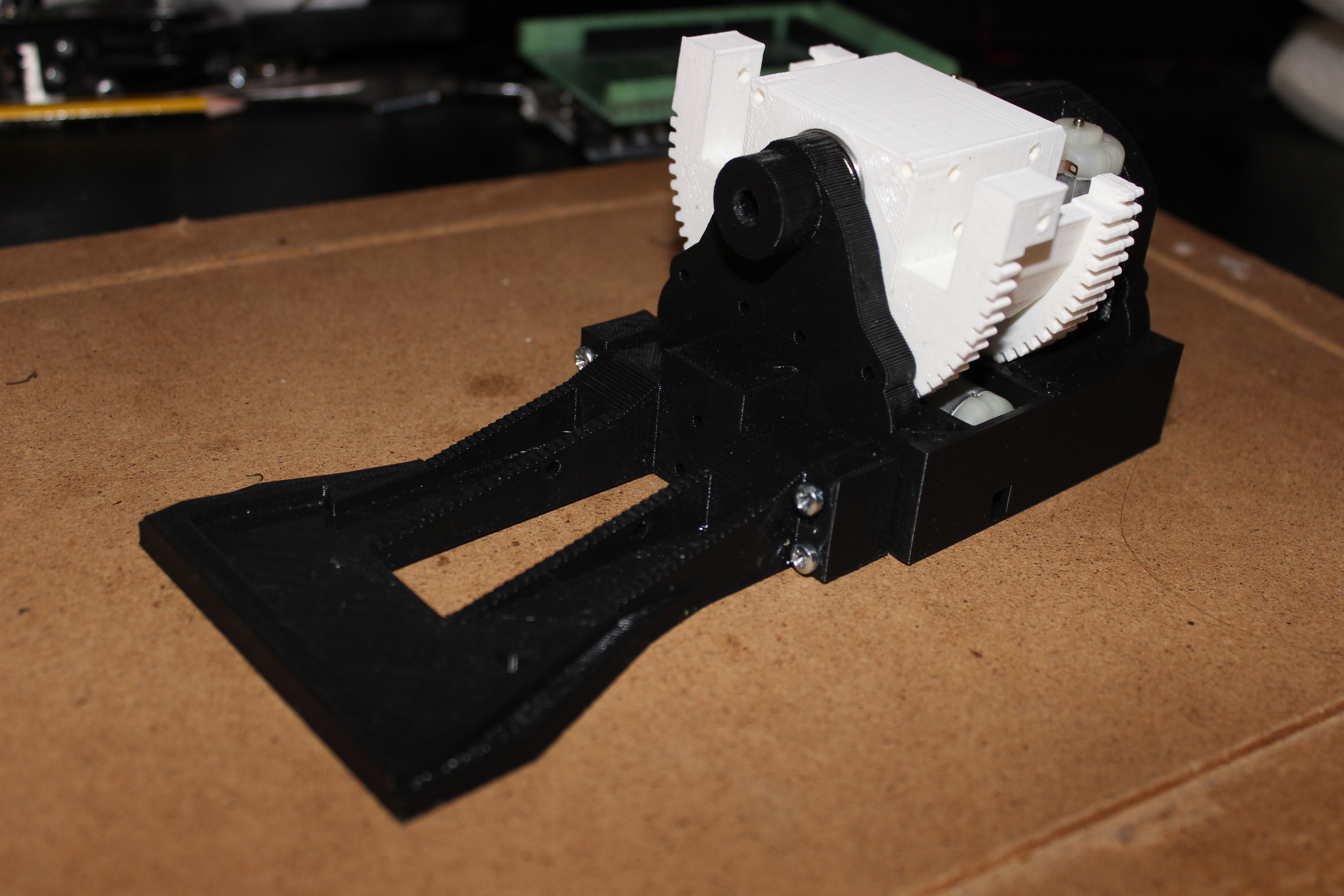
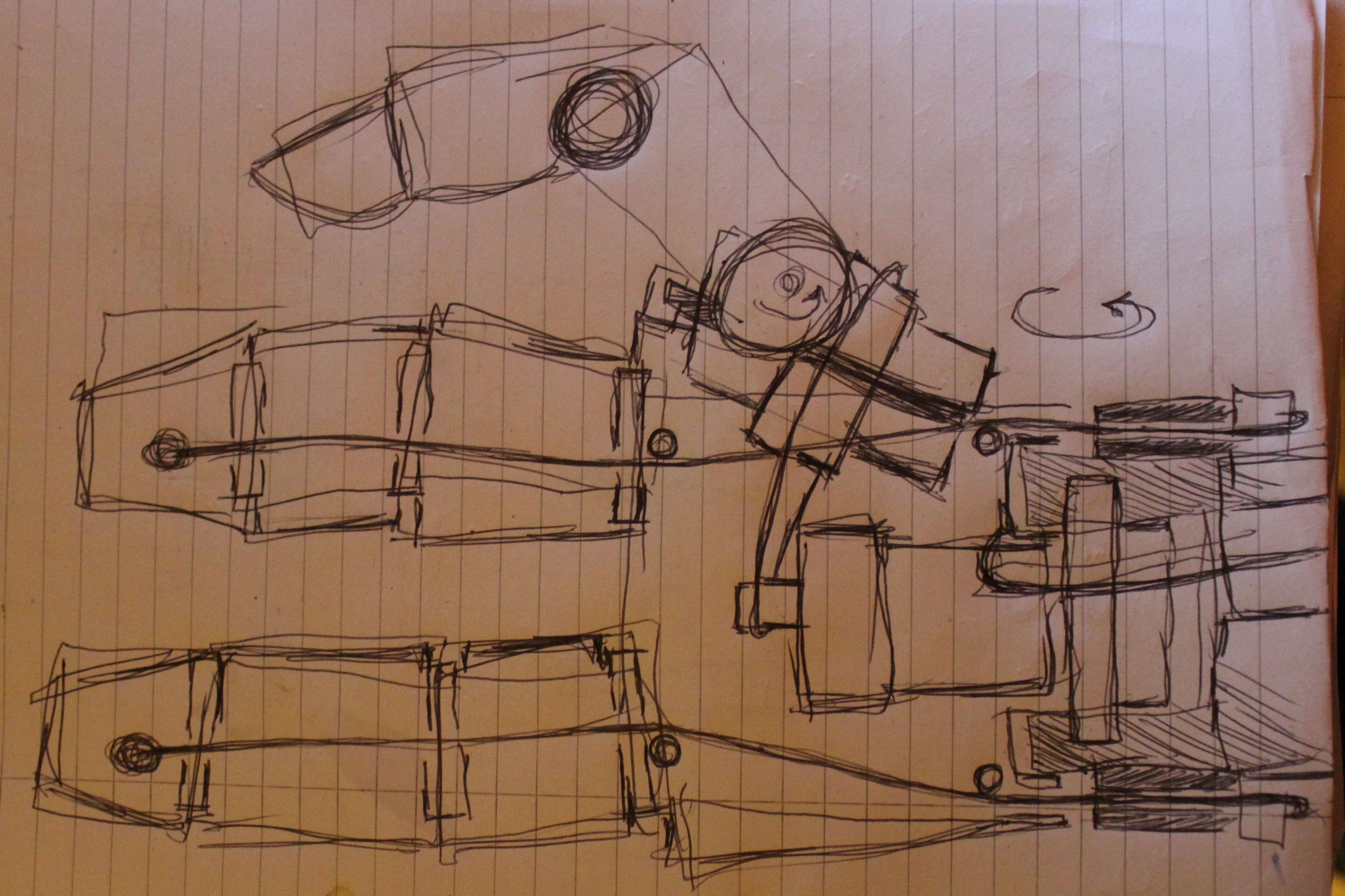
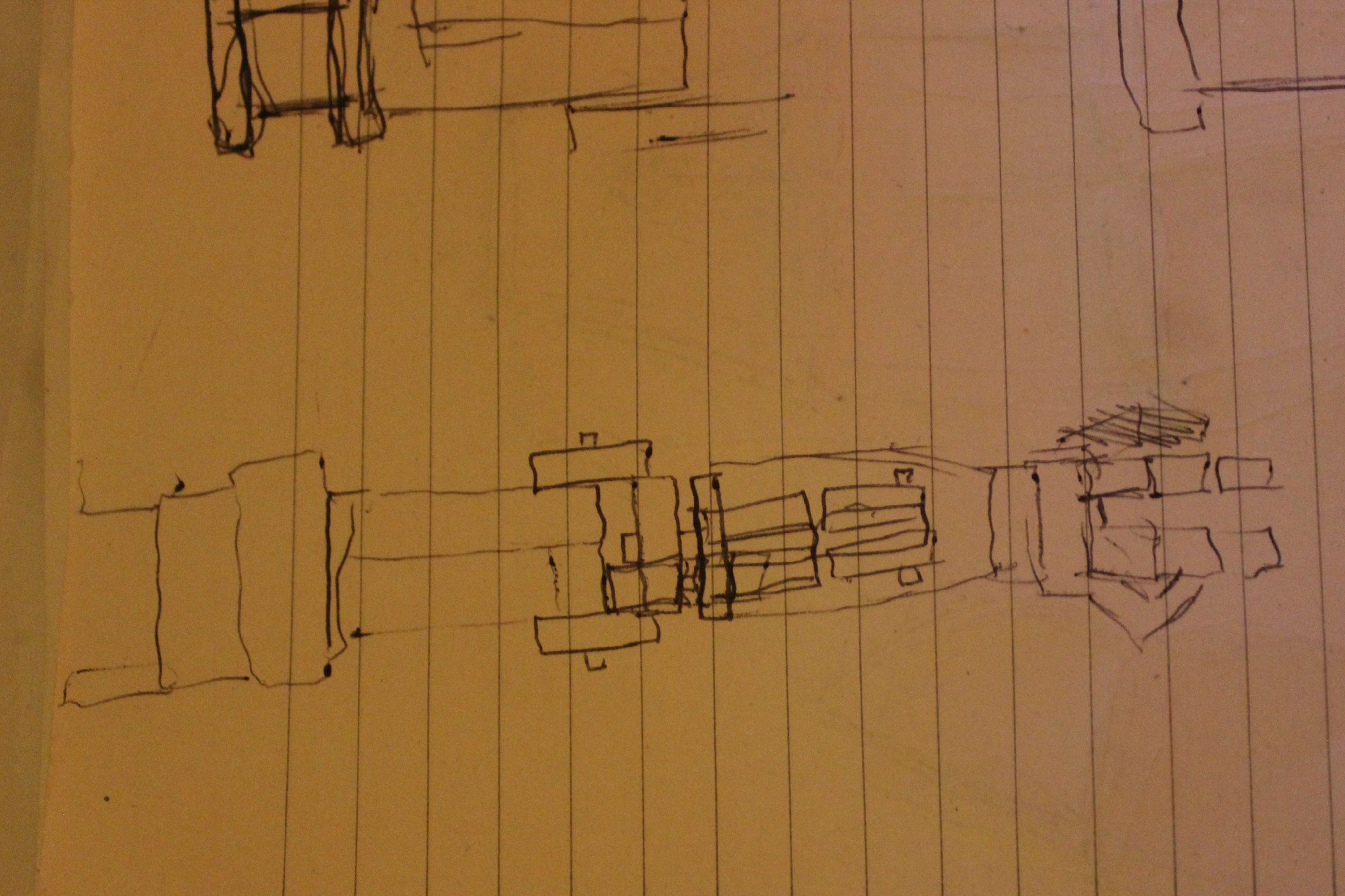
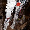
All of the joints are made using cheap plastic gearboxes and position feedback is from potentiometers. I am only at the point of making the legs and programming the arduino to control them in a usable manner. I managed to get it to stand on one leg yesterday, but much more work is needed to get it balancing using any kind of responsive intelligence. It doesn't have any upper body weight so counterbalancing is quite difficult at the moment. I haven't actually designed the upper body yet, but I have a good idea of how I want it to work.
I am planning to add gyro stabilisation and pressure sensors to the feet, although programming the responses to that data is going to be a real challenge and will probably take weeks.
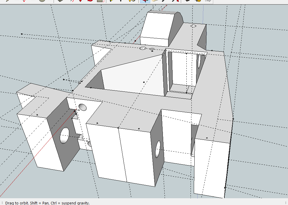
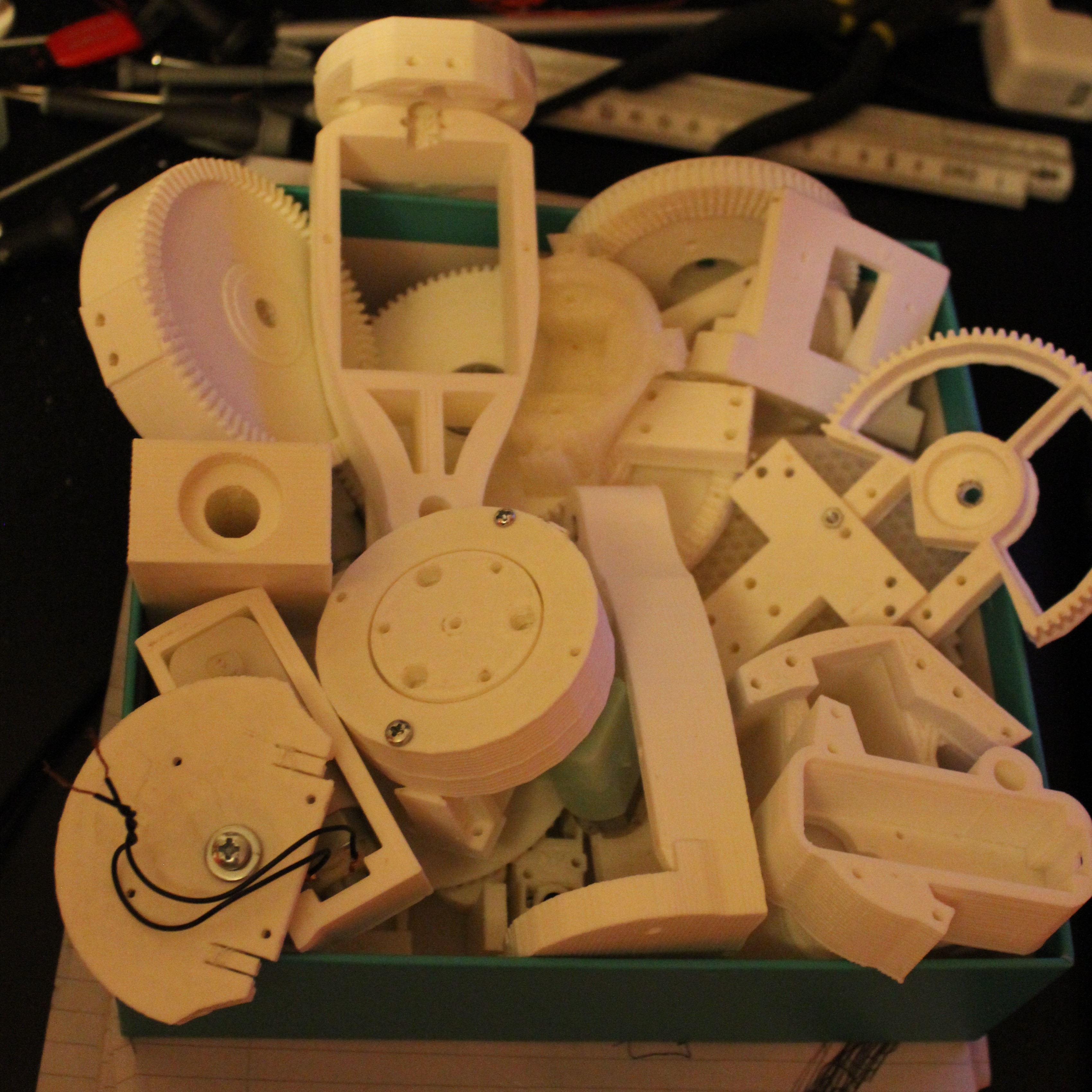
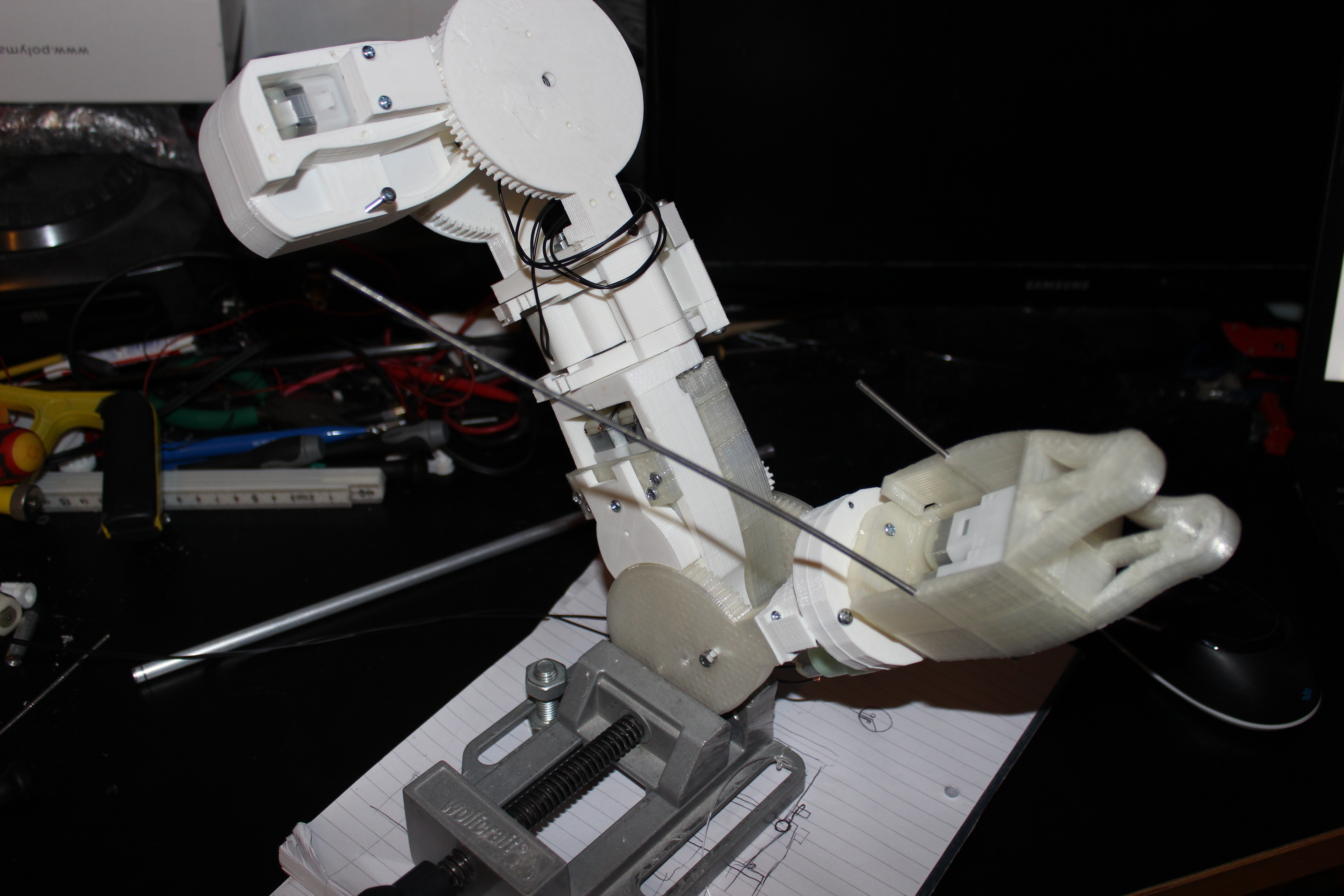
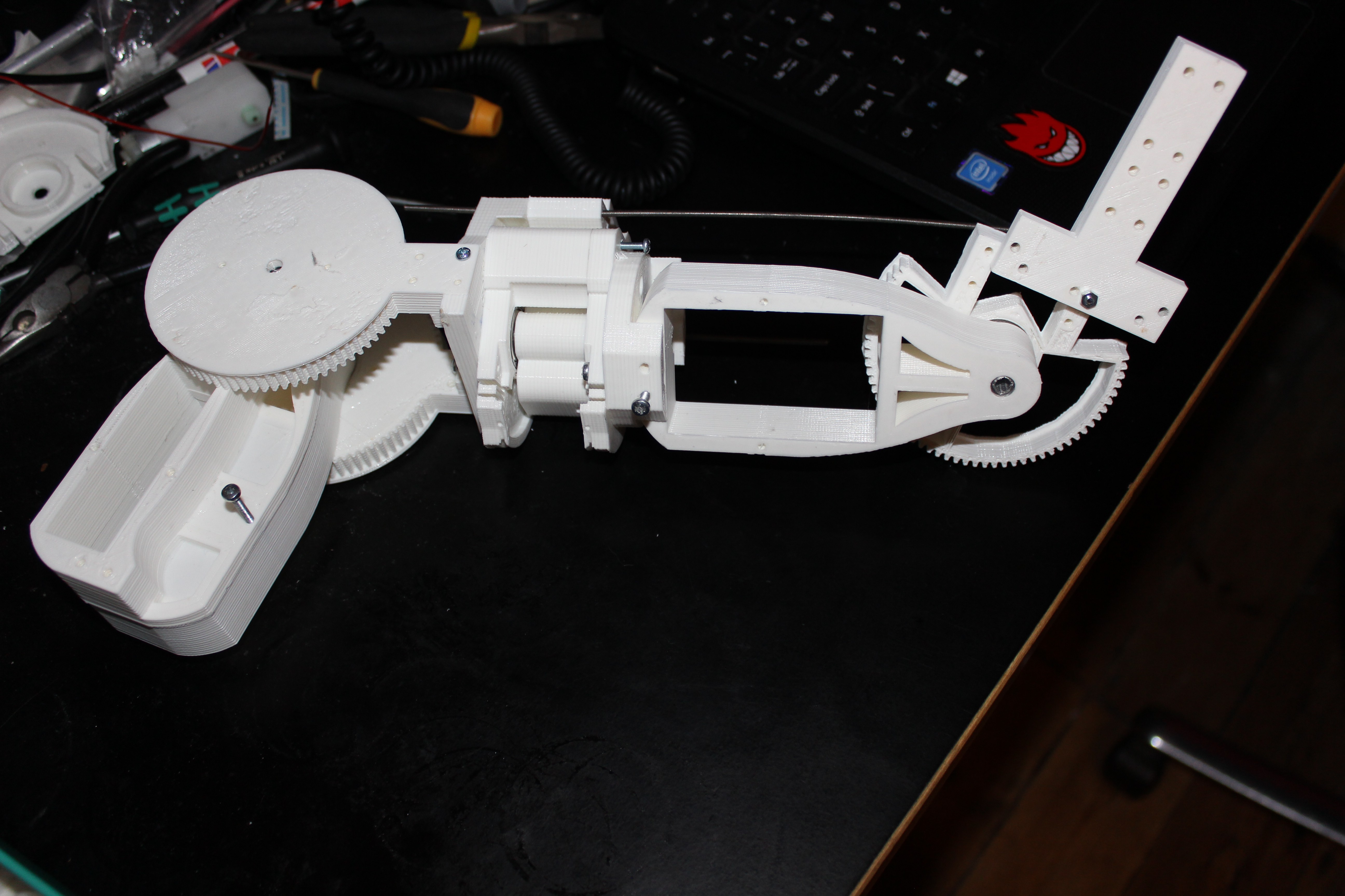
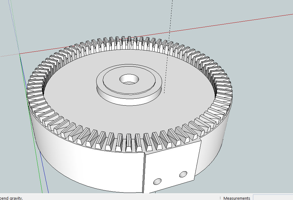
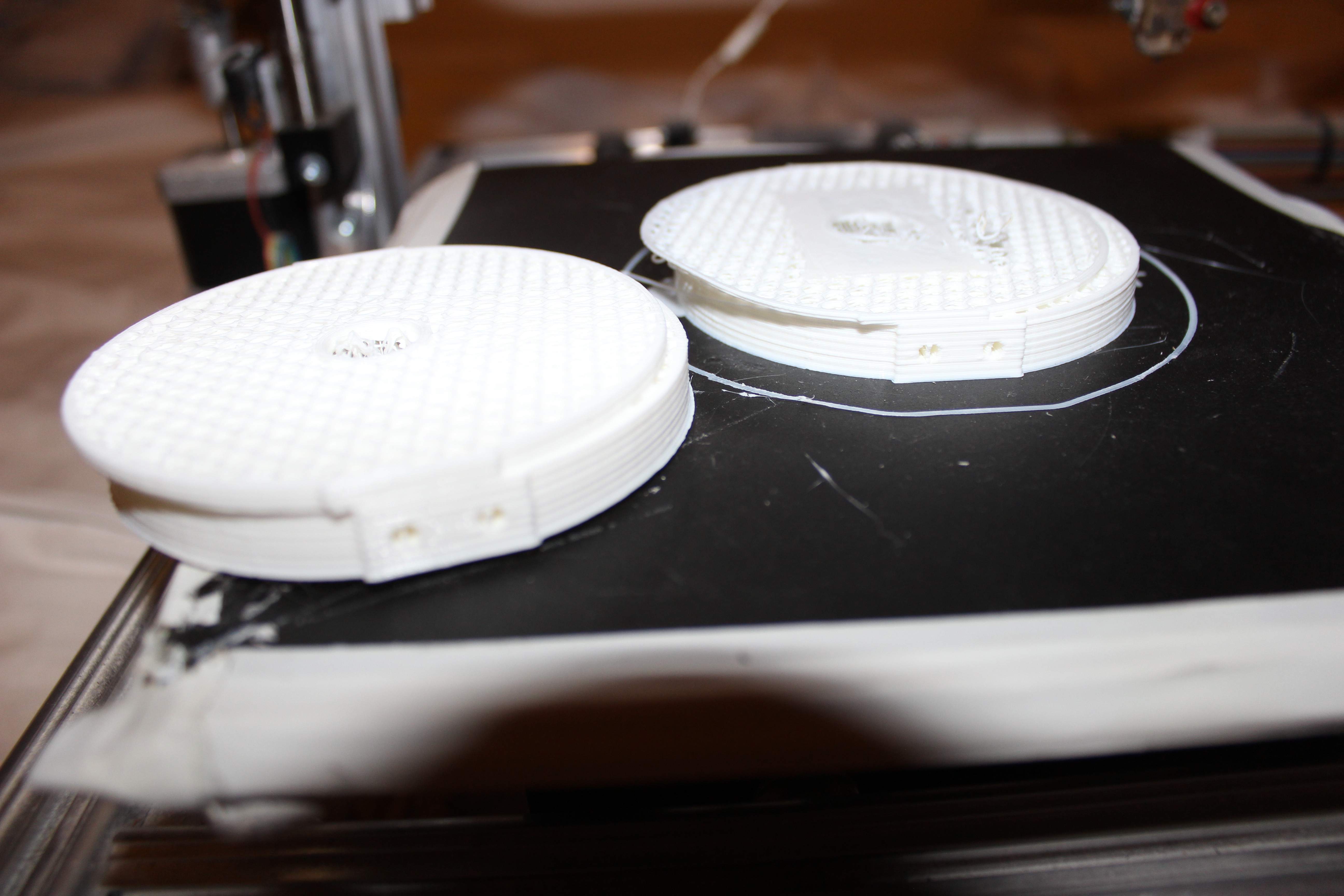
All of the plastic parts are 3D printed and designed on sketchup. I am using L298 breakout boards you can get on ebay for the drivers, quite simply because of the time saving and cost factor.
Each leg has 6 degrees of freedom and it can move in any way a human could conceivably move.
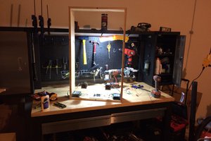
I took some time to learn a bit of Processing which is helping with control of the legs. I wasted days and days learning how to send data between the arduino and PC using the serial bus. It was extremely painful! I had to break down 3 digit integers into individual characters to send in a String and then vice versa on the other end. I cracked that eventually.
I am aiming to program everything through Processing on my laptop and then purchase a powerful 'on board' PC solution so that the processor can be located on the robot. I can then transfer the Processing files on to that.
You can see some big gaps in the shins, this space is where I will house the batteries. I will use the high capacity hobby battery packs that are usually used for RC cars etc.
I am going to spend the next few days getting saved movements sequenced so that they play back in a way that will make the legs walk . I also going to install the giro and pressure sensors on the feet.
Please get in contact with me if you are a company interested in supporting this work. I have everything I need to carry on and make these units, but I just need time. For that I need to have some level of support.
Updates to follow.
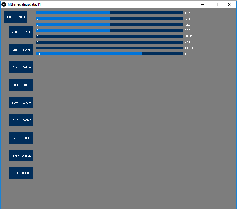 The squares give me the option to remember a movement by pressing teh number and then replay that movement by pressing the button next to it.


 Nathan Peterson
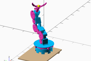
 Les Hall
 Patrick Joyce
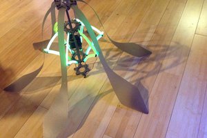
 Sarah Petkus
awesomeI