 The Big One
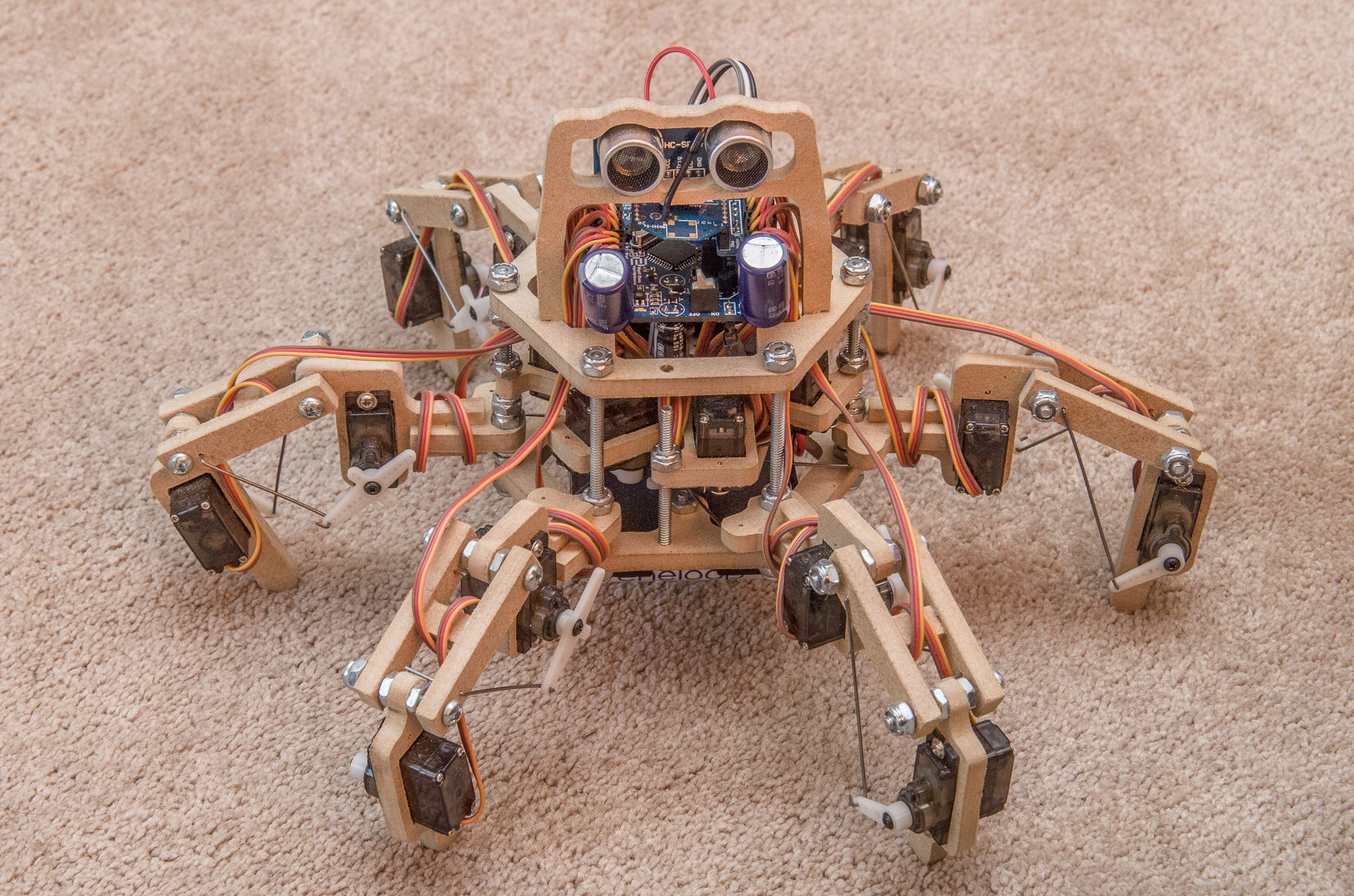
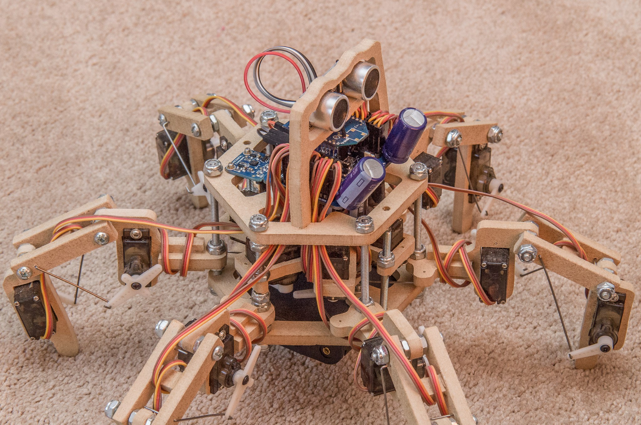
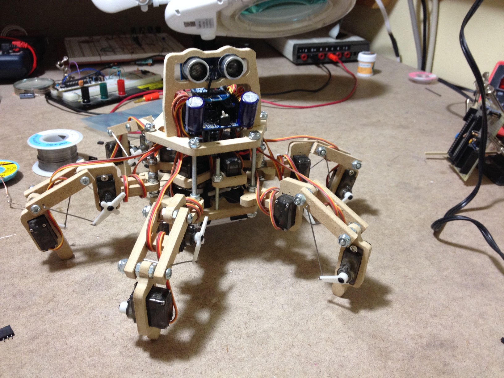
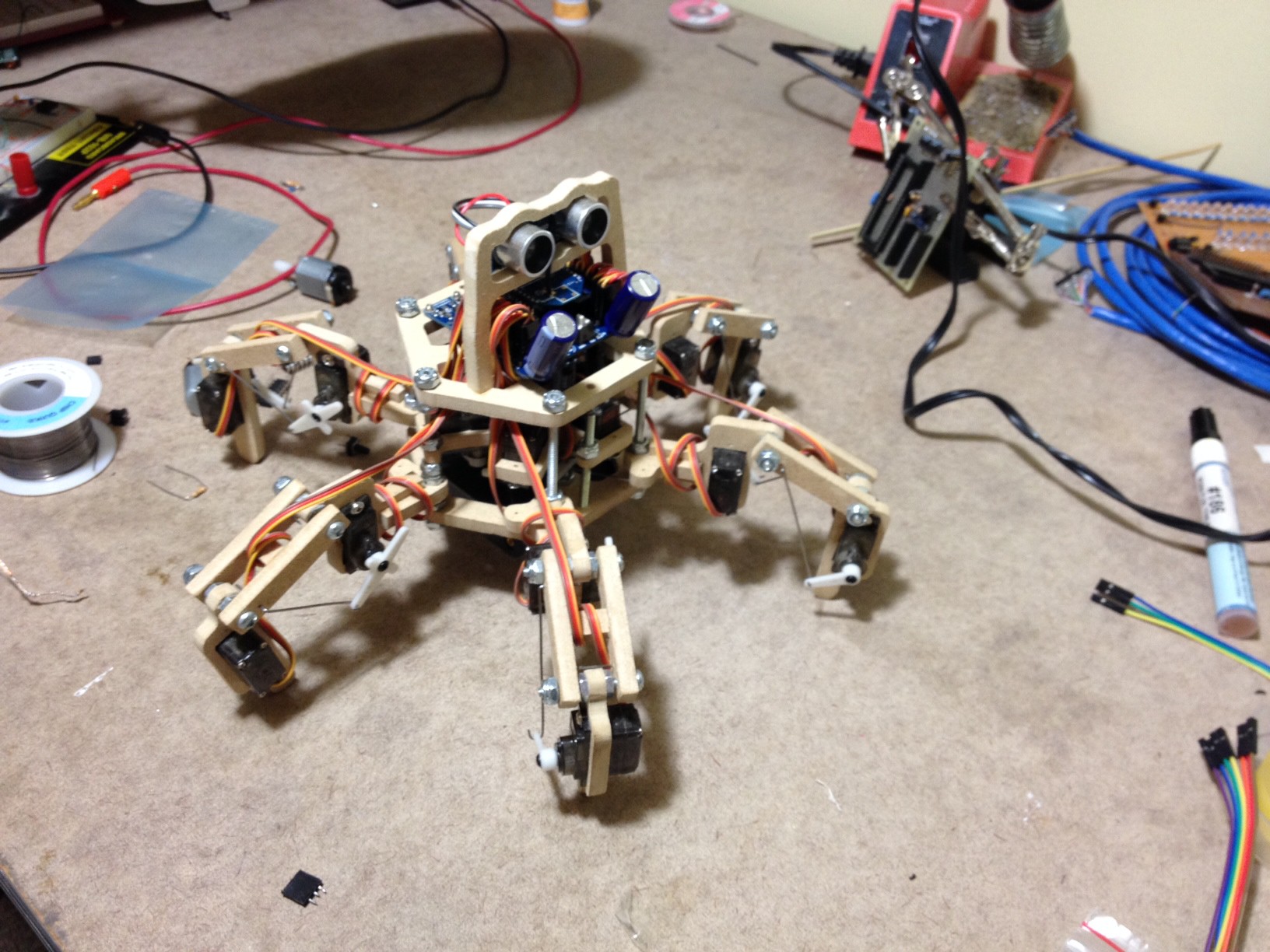
Since we started, Stubby has grown from a simple, direct-driven 2 DOF (degree of freedom) per leg frame to a mechanically-assisted 3 DOF per leg design with a full inverse kinematics engine (which allows the processor to calculate custom foot positions for each step, rather than relying on a static loop).
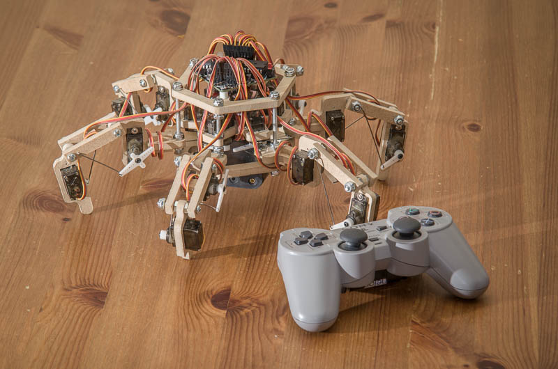 This video shows off the latest version, including various features of the Inverse Kinematics engine:
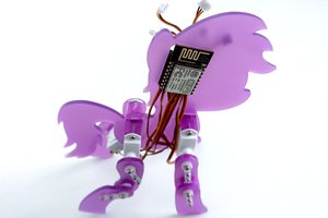
Originally, the concept of Stubby came from the SG-1 universe's replicators (which, let it be known, are completely awesome!). The name 'Stubby' was coined by Princess Sparkle, after seeing the first version (with 2cm long, oblong legs), barely able to limp along the carpet.
After the interesting parts (most notably the frame design and inverse kinematics engine) were completed, I wanted to expand Stubby's abilities. The Hackaday Prize made me think about 'connected' projects... at the same time, Princess Sparkle was expressing interest in computers and programming. In talking with her, we came up with the idea of making an API which would allow her to issue simple commands to control the robot.
This is not the first time she has done this sort of thing... in her Grade 1 class, there was a unit on Lego Mindstorms robots, which taught the children to visualize arithmetic expressions by programming the robot to, for instance, move 10 units forward and 3 units back, and seeing where on a number line they were (10 - 3 = 7). With Stubby, the plan is to expose more of the programming structure to her, teaching such things as procedural control, calling methods, assigning variables (by reading sensors), etc.
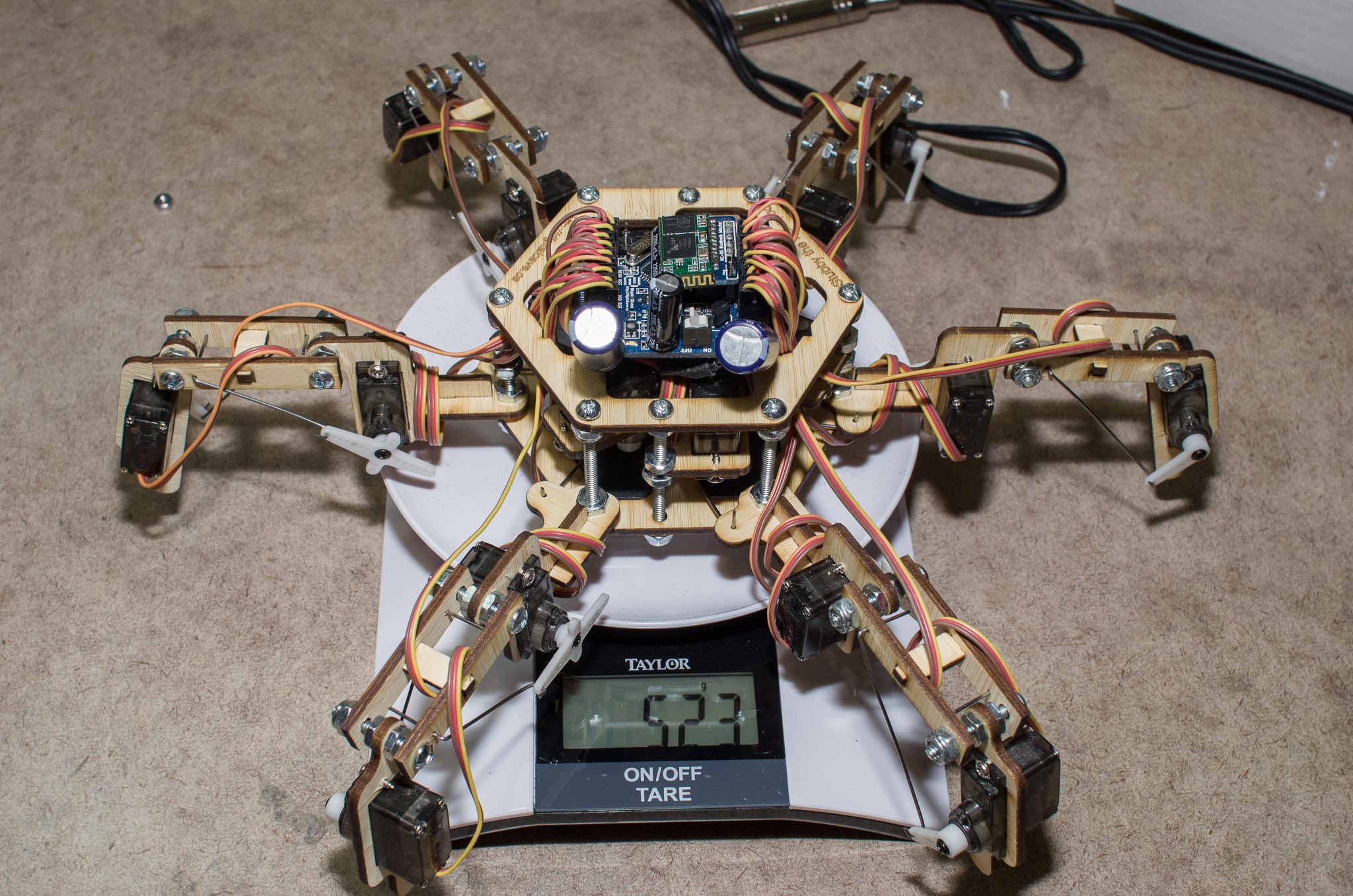
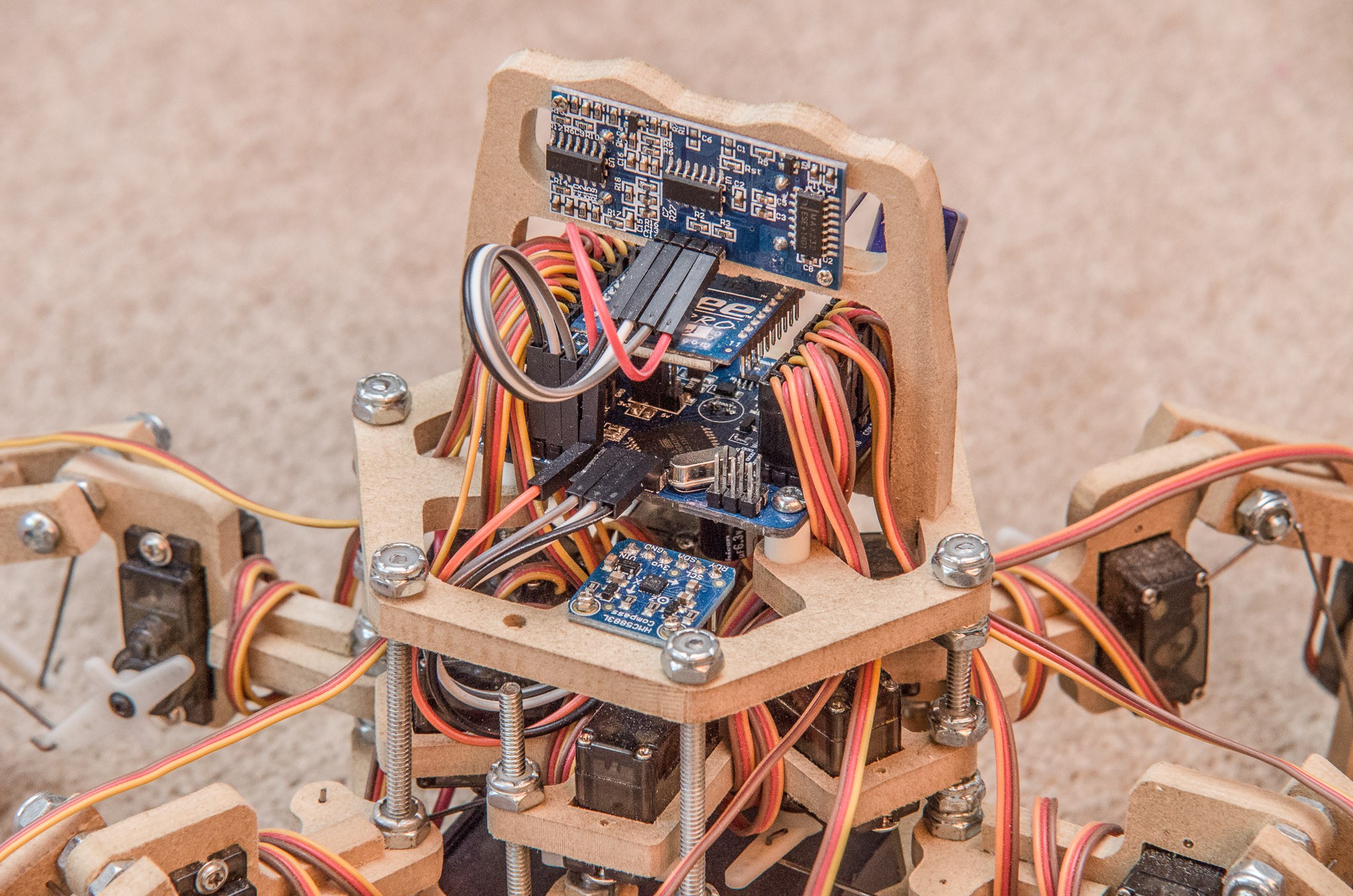
When finished, I plan on having an Ultrasonic Distance sensor and a magnetometer, together allowing users to write code for autonomous operation. An array of UV LEDs + photodiodes on the bottom will allow for writing line following algorithms. An i2c header is broken out, so that hackers can add completely new components as well.
Please refer to Youtube for THP Submission video and THP Semifinals video. Judges: see the Semifinals Requirements log for details on how Stubby achieves THP requirements.
For those who are interested in building their own version of Stubby, I have all the designs, plans, and theory available for all to use and modify freely. There are two documents which encapsulate the majority of my work.
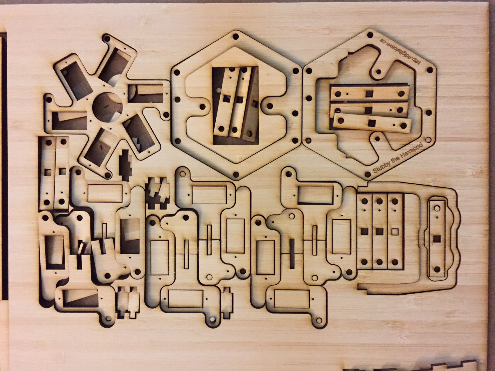
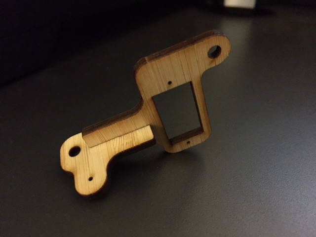
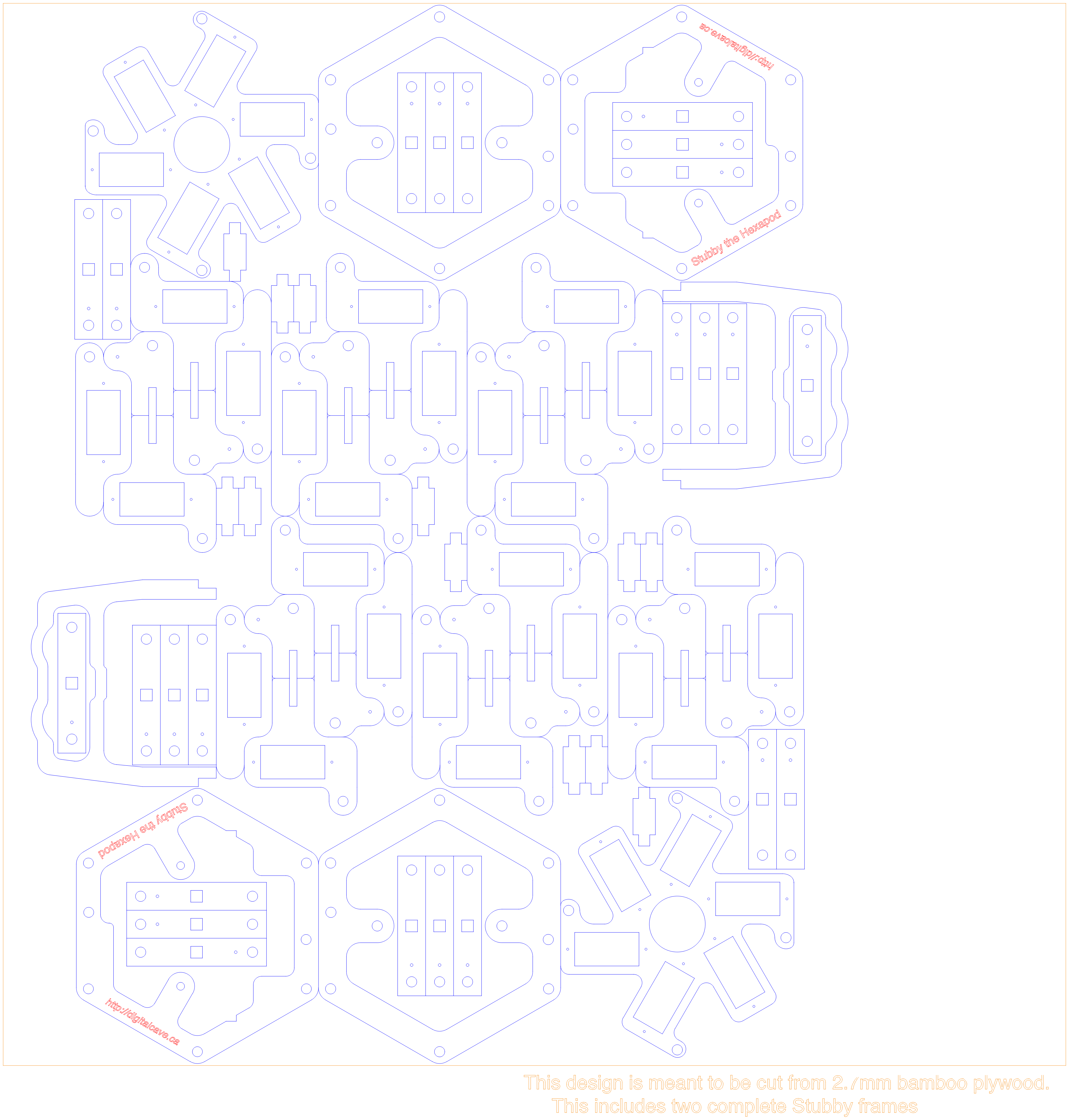
First are the frame plans. The frame is one of the biggest advantages which Stubby holds over other, more expensive hexapods. The first difference is the materials: Stubby is designed to be cut from 1/4" MDF using a scroll saw. (However, the design is adaptable enough to be able to use other materials as well, and the community has modified these plans for use with a 3D printer, laser cutter, etc.) The frame is quite easy to make; simply print the plans, tape it to an 8.5x11" sheet of MDF, and cut along the lines. The second difference is how the servos are attached to the legs: Stubby uses push rods to convert distance to torque, allowing Stubby to work with cheap, low-torque servos (at the expense of being a bit more limited in leg movement). This is the biggest factor in being able to keep below $150 in components (this assumes you have no parts in your parts bin, but does assume that you have all the required tools already).
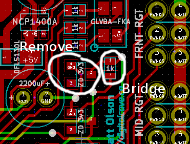
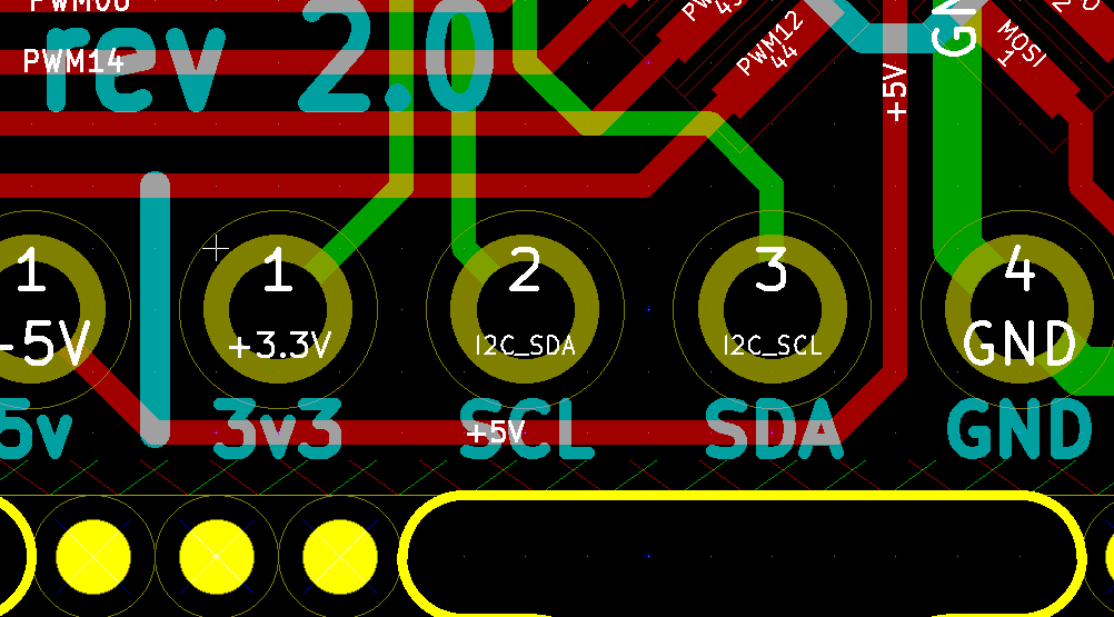
The second important diagram is the circuit board schematic. This shows how to wire the control board so that the microcontroller can perform the needed calculations and tell the servos how to move.
The hardware is useless without software to control it. You can download or browse my git repository, which includes all software, electronics, and frame design.
Everything needed to make Stubby, both hardware and software, is licensed under a Creative Commons Attribution-Share Alike License).


 deʃhipu
 Ranarchy
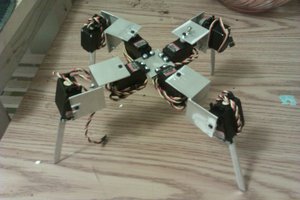
 morgan
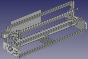
 Kārlis