 morgan
 Tindie
 EK
EK xBeau
xBeau-
How do you figure out how much paste you need?
07/31/2019 at 01:03 • 3 commentsSo I'm trying to figure out how much paste I need to order for an upcoming run and have just run up against a lot of sciencey sounding math and formulas that require info the datasheet doesn't provide. I made some assumptions, like solder paste having a Specific Gravity of ~4.14g/cm3. I then calculated the area of solder paste on my board, ~353mm2. And the volume for a 0.12mm thick screen, giving me 42.5cm/3. area / SG and this calls for ~85 grams of solder paste. Does this sound remotely reasonable?
In addition to this, how much extra should I account for? It comes in 50g or 250g and if two 50g will do I will be happy (and have ~$40 more on hand)
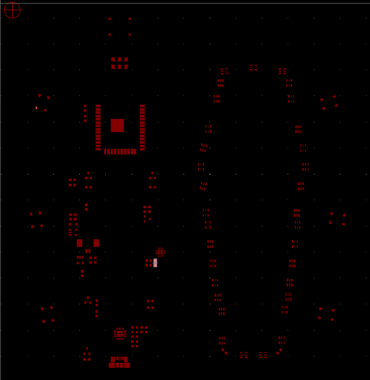
For reference here is the board, the highlighted part is an 0603 resistor with a 1.05x0.95 pad.
-
Can you identify this connector?
07/10/2019 at 01:29 • 6 commentsTrying to use the same connector on my project as is common on TTGO boards as I have a lot of them with batteries to match. I've been searching and searching but cannot turn up anything. Looks a lot like Molex 0532610271, or maybe but not quite like a JST SB series, kind of colored like the Amphenol connectors. It's 1mm pitch.
And if you don't know what this is but just love sharing your opinion on the internet, I'd also be interested in hear what other people like in the 1-1.5mm range SMD battery connectors.1mm mystery connector -
Hide a button in your button
01/25/2019 at 02:19 • 1 commentoh the ideas that pop up when in #Hack Chat .
While batting around some ideas about using clusters of vias as capacitive touch inputs @Morning.Star brought up an excellent point, one that was already in my mind as usual. Haptics are important. Despite the fact I'll likely be the only person using this, designing accessible interfaces >IS< important. Make it a habit.For this design, I wanted to keep the overall profile as low as possible. This was one of the main reasons to use capsense instead of buttons. The second reason was to "discover" the buttons in the design. The next suggestion from @Morning.Star (jokingly?) was why not use both! ....Why not indeed!
I went digging and found some nice button that checked all the boxes. Flat enough to not obstruct the overall profile, visually there are a pretty good fit for my overall theme and most importantly, flat enough that I though capsense underneath was feasible.

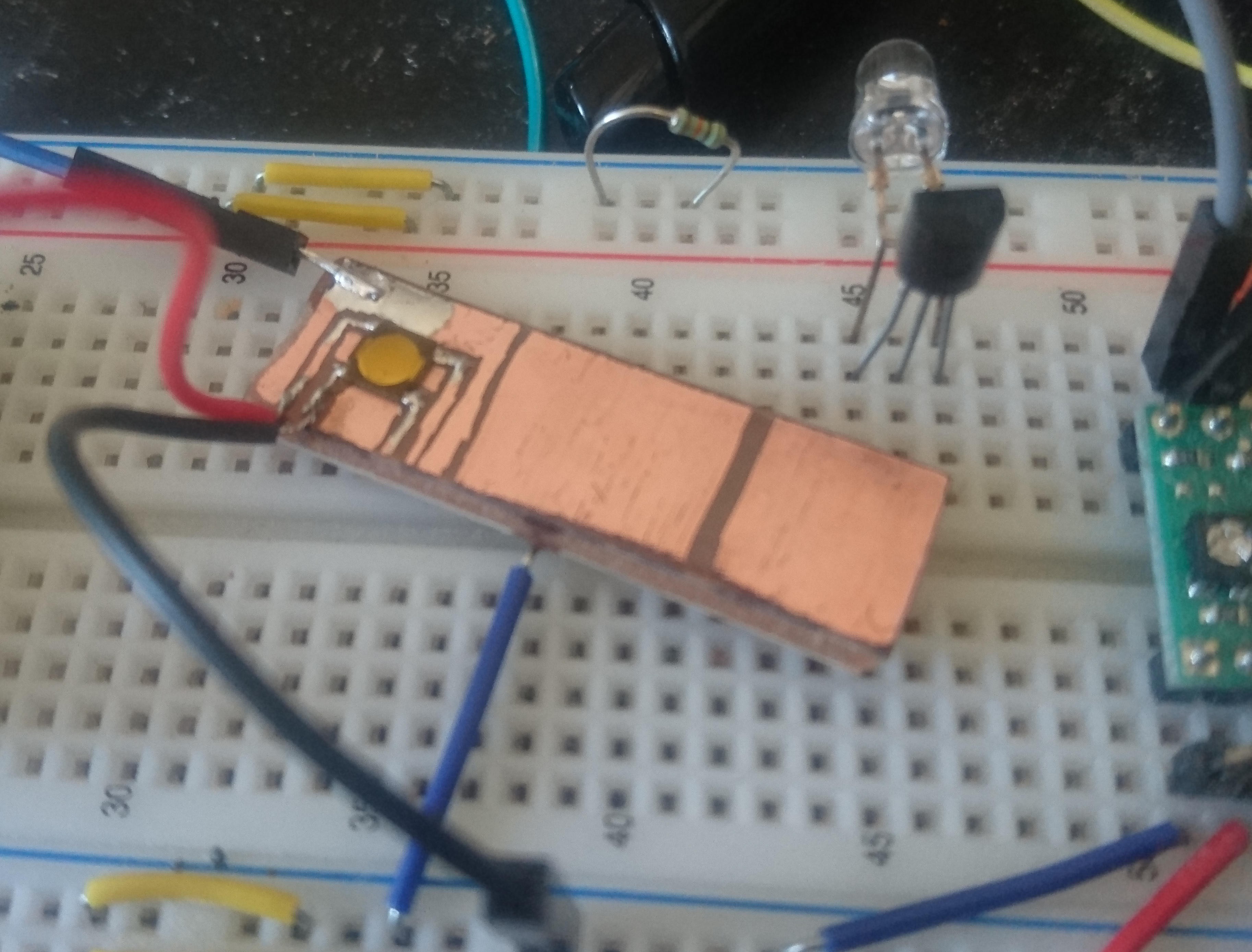
The button For a test I busted out the ol' #SharpieCAD and make a simple test board.

The idea here is too keep as much copper as possible around and beneath the button footprint.
![]()
Alrigh! Button soldered up! The red & black wires coming down are the for the button and the blue one up top is for capacitive touch. The blue breadboard wire going underneath is connected to the backside ground plane.
This project will be using the ESP32 as always. This is handy as it has a Touch Input peripheral and good example code. Took just a few minutes to have a test working. Only odd this I ran into is the way a the "pad_num" argument for many functions is tied to one specific GPIO but not very clearly explained. Once that was clear the rest of the test code is pretty standard copy & paste from that example.
I'll call that experiment a success. With any luck the project this is going into will be unveiled towards the end of February. Thanks to @Morning.Star for both the common sense reminder of the importance of accessible interface and the silly experiment idea.
My Pages


Projects I Like & Follow
 Max.K
Max.K Kevin Santo Cappuccio
 Mitsuru Yamada
 Kaushlesh C. ( KD9VFU )
 Nik Reitmann
 Garra
Garra Anders Nielsen
 Salim Benbouziyane
 Addie Liu
 T. B. Trzepacz
 Rex.Tang
 hayden
 davedarko
 deʃhipu
 bobricius
Share this profile
ShareBits


Hi Morgan, thanks for your interest in my #LiFePO4wered/ESP32 project!

No worries! I stumbled across it will doing primary design/outline on something not too dissimilar (not as general and not commercial), which I'm also using some of your Solar1 modules to do preliminary software testing. Look for a report on that soon. I've also learned a !TON! reading your posts on the design over the weekend, thanks for the detailed write-up, extremely helpful for someone like me without the formal EE background.
Glad to hear my posts are useful to you! :)
Hi Morgan, thank you for liking and following Kobold K2 RISC computer !

I still havent forgiven you for #Venusian Star Palm BTW. XD
I havent turned one of my friends into something in a while... ;-p

Thanks Morgan, for the skull on #EXPLOG : Exploration Logger :)
Thanks for liking windicator! Stay tuned as hardware is being built this week!
Very cool! I hope to send boards for https://hackaday.io/project/21067-loranet32 to fab this week too! Good week for building I think.
Thank you for liking my #PERSEUS-9 homemade mobile 6502 computer !