Close
0%
0%

Tote Zero

Affordable quadruped robot powered by a Pi Zero

Similar projects worth following
Now that Pi Zero is here, it fits in the budget I have set for Tote, so here's a version powered by it.

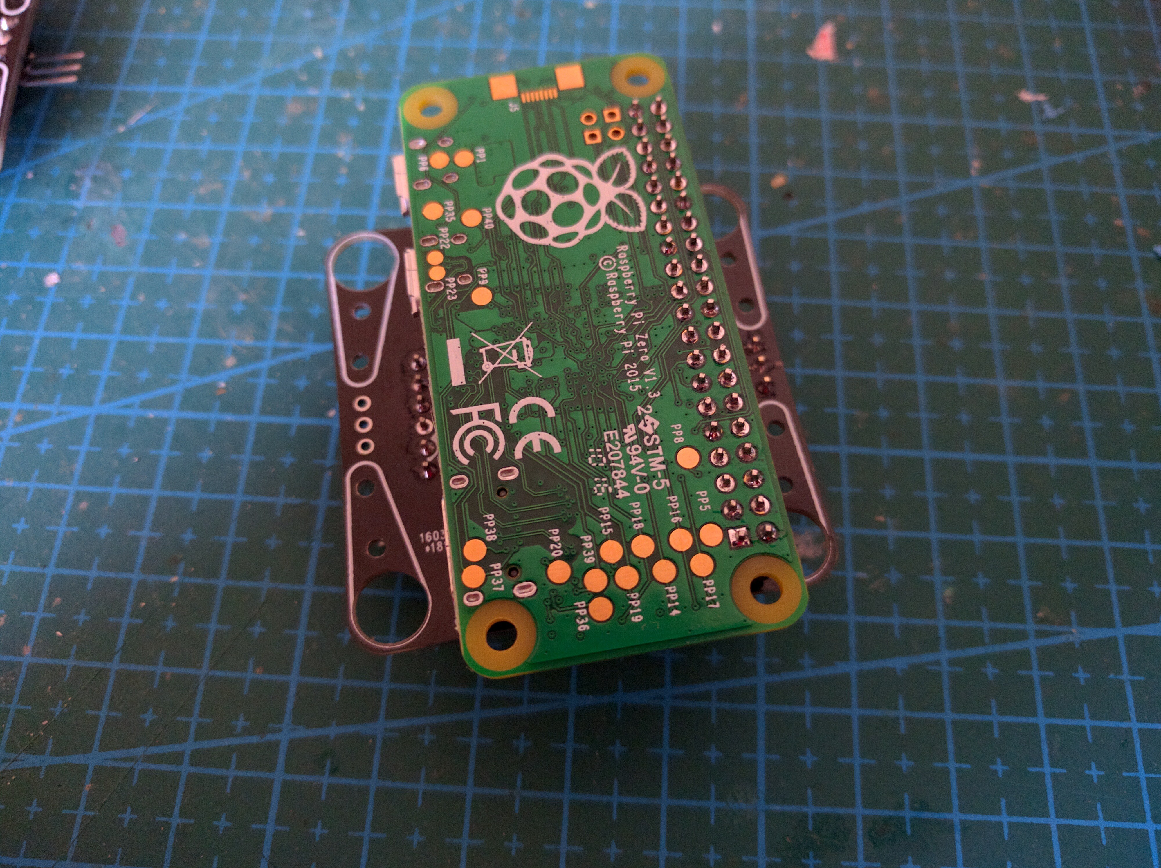
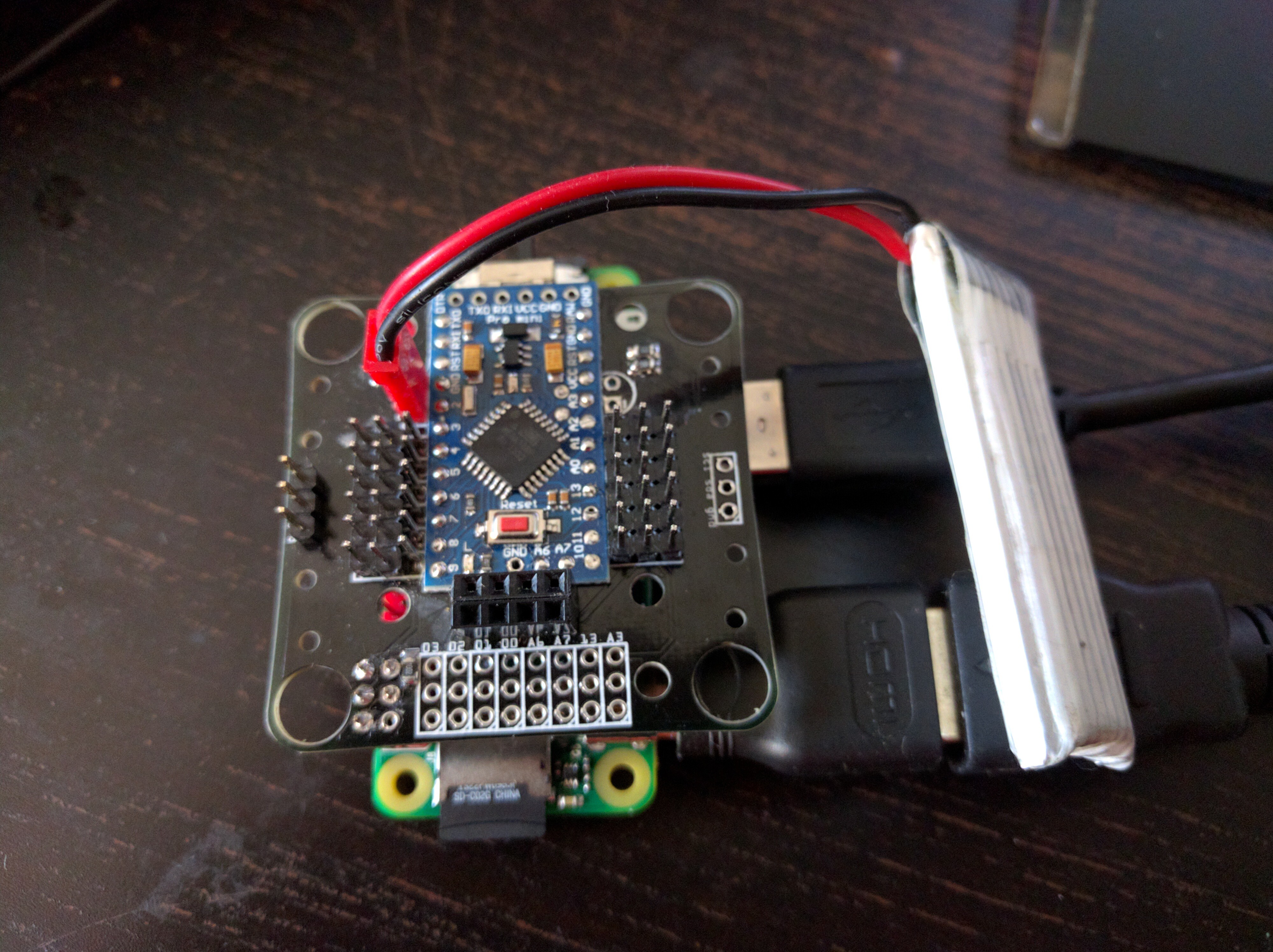
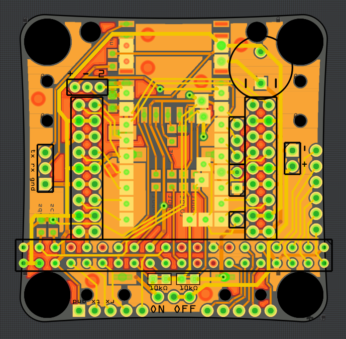
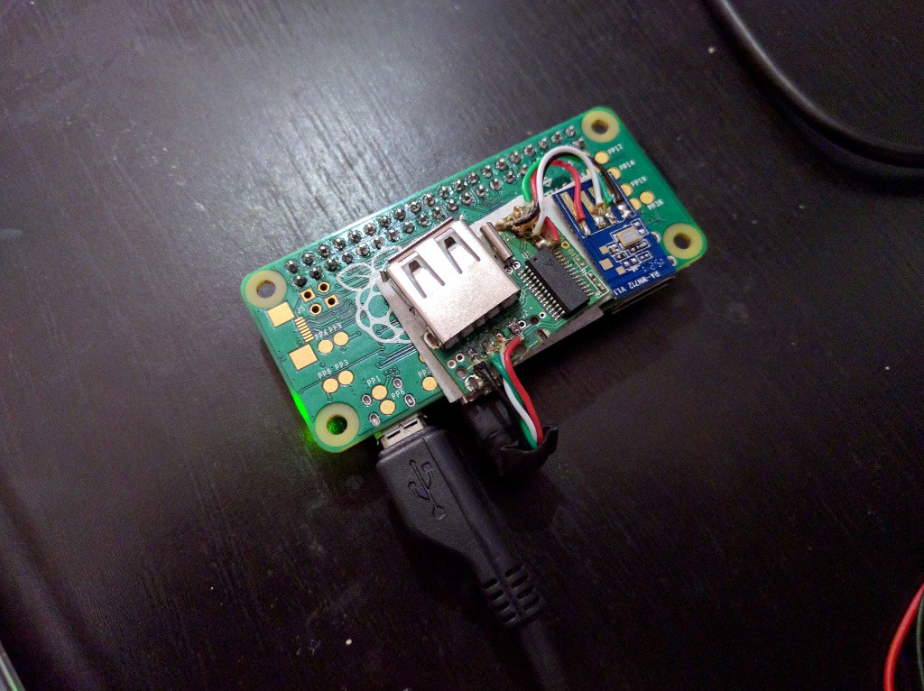
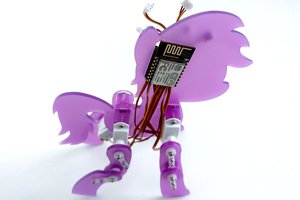
The original #Tote used an Arduino Pro Mini clone for its brains, as this was the most affordable option available at the time, and reasonably easy to use and program. But now that there is a $5 single-board computer available, why not use it instead?

The advantages, as I see them, are three-fold:

  • using Python for programming, which makes it much easier to both write code and test stuff in the interactive console,
  • possibly integrating this with ROS, OpenCV and other awesome tools,
  • much more computing power, which means that more interesting things can happen.

  • 1 × Raspberry Pi Zero A+ works too
  • 12 × SG90 Microservo Or any other model of a small, 9g microservo
  • 1 × Custom Printed Circuit Board https://bitbucket.org/thesheep/tote0/downloads/tote0.zip
  • 1 × XM1584-based Switching Voltage Regulator Module
  • 1 × 2S 300mAh LiPo Battery Or any other 2S LiPo

View all 7 components

  • Robot Fusion

    deʃhipu11/06/2016 at 10:38 0 comments

    So I never actually made that board from the last log. But remember #Tote HaD, those robots that we have built at Hackaday Belgrade? I have spent a considerable amount of time designing that PCB, and it has a couple of Easter eggs in there. On of them is that unpopulated pin header in the lower right corner:

    Turns out that you can put a female pin header in there:

    And then, instead of plugging that ESP8266 module in the usual socket, you can plug a Raspberry Pi Zero in there:

    The power from the LiPo is only between 3.7 and 4.2V, but turns out that this is enough for the pi -- its regulator will switch into a low-voltage mode, and everything works:

    Next, I will just need to take the MicroPython code I used on the original, and touch it up to run on regular Python on the pi, with the SMBus library for the I²C communication.

  • Everything in One?

    deʃhipu02/11/2016 at 12:38 0 comments

    o I haven't done much work on this during the week, but I did do some thinking, and the results of that are pretty scary. First, I realized that using Servo Blaster and all those pins is not really that convenient, when I can simply have a #Servo Controller from a Pro Mini. Second, while Pi Zero is cheap, a WiFi dongle and SD Card for them are not. ESP8266 is cheap, though, and you can do #RPi WiFi with it. Can't really do much about the SD Card, apart from using a cheap, small one.

    Anyways, putting it all together, I got something like this:

    It has room for ESP8266, Pro Mini and Pi Zero, 12 servo sockets, IR sensor socket, and a voltage regulator module. I had to use both sides of the PCB with surface pads, and the RPi header doesn't quite fit on the 5cm board, but that's details.

    How would you use this? There are three options. Only put a Pro Mini there, and you have the simple version of #Tote with remote control. Add a ESP8266 with the right firmware, talking to the Pro Mini over I²C, and you have a Micropython or Lua-based robot with WiFi. Finally, add a voltage regulator and Pi Zero, and you have a perambulating computer, with WiFi over ESP8266 and possibly a USB camera.

    Will this work? I honestly have no idea. I cobbled this PCB together over several evenings, stealing ideas that I don't fully understand all over Hackaday. It does, however, sound like the right way forward.

  • Face

    deʃhipu02/07/2016 at 20:25 0 comments

    I also needed to figure out a way to attach the camera to the robot in a robust way. So I drilled some holes in the plastic that holds it, and screwed that to the Pi Zero:

    This is with just the camera connected to the USB. But for development it's nice to have both the camera and WiFi, so I repurposed that two-port hub I had, and made an alternate cable:

    Of course googly eyes are very important too!

  • Camera

    deʃhipu02/07/2016 at 13:40 0 comments

    Today I worked a little bit on adding a camera to Tote Zero. Most of this I have already done for #Pico-Kubik quadruped robot, but I thought I will do a more detailed write-up. I started by digging up from my junk pile an old camera module from a laptop. You can usually find those in electronic junk, or, failing that, buy them as spare parts for a dollar or two. Mine looked something like this:

    Read more »

  • First Walk

    deʃhipu01/27/2016 at 14:00 0 comments

    So today I figured out which servo is on which leg, rebuilt the legs to make the coxas longer, trimmed all servos again, added pieces of rubber tube as feet, and replaced the battery with a larger one.

    I also adjusted the voltage to be exactly 5V (it was 5.2V for some reason), hopefully that will make this thing heat less.

    Finally, I made some small fixes and adjustment to the code, and lo and behold, we have a walking robot!

    It's still not perfect, of course, but at last it works.

  • One Step Forward, Two Steps Back

    deʃhipu01/26/2016 at 22:55 0 comments

    Today I finally adapted all the code for IK and walking, and realized that practically everything I did yesterday is wrong.

    First, the cheap WiFi dongle that I soldered to the mini-hub is really bad. It gets hot and eats enough current to make the Pi Zero restart when the servos move. I had to switch to console over serial.

    Second, before you laboriously trim all the servos to the right positions, make sure the new servo library that you wrote takes the same range of angles as the old one. In this case, the old one took -90° to 90°, and the new one takes 0° to 180°. The result is that all the servos are wrong by 90° and I have to redo the trimming.

    Of course the board has a tendency to restart when all the servos are switched on simultaneously anyways, so I had to add some code that switches them one by one, with some delays. Nothing new here, old #Tote had the same thing, and it's a good idea anyways.

    I still have to figure out which pins are for servos on which legs -- I didn't keep track of that when connecting them, and I figured it would be easier to just go one by one in software and see which leg moves.

    Hopefully I can get the first walk by the end of the month.

  • Single-port USB Hub

    deʃhipu01/25/2016 at 21:36 1 comment

    In order to make working on the robot a little bit easier, I added a small USB hub that I had lying around, with a cheap WiFi card soldered to it. This way I have access to the board and still can use a single USB port for, say, a webcam.

    Otherwise the progress has been slow. I adjusted and trimmed the servos, so that the robot can stand in the "zero" position, but I still haven't tested the inverse kinematics or walking code.

  • Fixed Board

    deʃhipu01/07/2016 at 21:49 0 comments

    After some cosmetic touches, I'm finally happy enough with the first version of the PCB for this robot. It looks something like this:

    The Fritzing file is in the repository, and the Gerber is available for download. I used a new approach for the servo sockets -- since the Pi Zero is going to be plugged as a second layer, we don't really have enough space for the usual servo sockets. So I used one long header with angled pins -- the servos plug in two rows into that, fitting between the Pi and the board.

    Other than that, the board has the serial and I²C pins broken out, and also a header for all the pins that are not used for controlling servos. There is also a jumper in there, for disconnecting the servo power from the Pi -- so that we can power the two from two different sources if we need to.

    The usual holes, as in Tote, are for attaching the servo horns for the legs.

  • Servo Blaster

    deʃhipu01/07/2016 at 20:47 0 comments

    So I have the robot assembled pretty much the way I wanted -- the PCB as the body, a XM1584-based voltage regulator for steady 5V to the Pi and to servos, capacitor, power switch, 2S LiPo battery. Nothing fancy, really. I have no voltage monitoring this time, because the Pi doesn't have an ADC that I could use (I might add one in the future versions), so I have to be careful about the battery use.

    I also have the Servo Blaster, the daemon I'm using to generate PWM signal for the servos, all installed and configured, and I have a simple Python class to use it:

    import math
    
    
    class Servo(object):
        def __init__(self, servos, index, reverse=False, trim=0):
            self.servos = servos
            self.index = index
            self.reverse = reverse
            self.trim = trim
    
        def move(self, radians=None, degrees=None):
            self.servos.move(self.index, radians, degrees, self.reverse, self.trim)
    
    
    class Servos(object):
        min_pos = 600
        max_pos = 2400
        unit = 4 # us
        max_servos = 12
        pos_range = 180
    
        def __init__(self):
            self.device = open('/dev/servoblaster', 'w')
    
        def __getitem__(self, index):
            return Servo(self, index)
    
        def move(self, servo, radians=None, degrees=None, reverse=False, trim=0):
            if degrees is None:
                degrees = math.degrees(radians)
            degrees += trim
            if reverse:
                degrees = self.pos_range - degrees
            position = self.min_pos + (degrees * self.pos_range /
                                       (self.max_pos - self.min_pos))
            position = min(self.max_pos, max(self.min_pos, position))
            output = position / self.unit
            self.device.write("{}={}\n".format(servo, output))
    
        def update(self):
            pass
    Now it's time for my favorite pastime (not): figuring out the order, orientation and trims for all the servos. Once I have that, I expect my code for the PyBoard to basically work -- which means that I should have the basic creep gait. For now, I can move each of the servos individually, while the robot lies on its back, with a wifi dongle connected for control:


  • Off By One Servo Plug

    deʃhipu01/05/2016 at 16:59 0 comments

    Mistakes in PCB design happen, and usually hurt when you receive your fabricated PCB. I was in a hurry to send the Tote Zero's PCB to fabrication before Christmas, so that I can receive it when I come back from the holidays. And as you can guess, I made a mistake. Instead of making the servo headers GVSGVSGVSGVS... (that's ground-voltage-signal), I made them VSGVSGVSGVSG...

    What now? Of course, I will eventually order another PCB (especially since this one doesn't have all the extra pins of Pi Zero broken out, and they may come in handy later for sensors or extra servos), but for now I would like to be able to test other aspects of my robot, so that the next design includes any fixes and ideas I come with. So I really want to use this board as it is.

    I could "fix" this by disassembling the plugs of the servos, and changing the order of wires in them. In fact, it's not a lot of work, even for a dozen servos. But from my experience, sooner or later I will forget about this, and either connect an un-modified servo, or use those modified servos for something else and release the magic blue smoke. I'd prefer to avoid this.

    So instead I plugged the servos offset by one pin, and glued additional pins in front for the one plug that sticks out and misses its ground pins (the additional pins are red):

    It's not pretty, but it will do for now. I also fixed my PCB design files already, so that I don't forget about it.

View all 10 project logs

View all 6 instructions

Enjoy this project?

Share

Discussions

danjovic wrote 11/18/2016 at 13:48 point

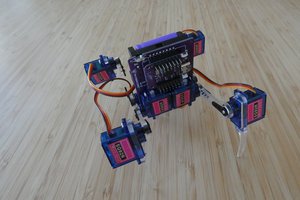
Congratulations, pal!

  Are you sure? yes | no

Craig Hissett wrote 11/17/2016 at 22:57 point

Congratulations mato,  well done for making the Enlightened Pi finalist list!

:-)

  Are you sure? yes | no

deʃhipu wrote 11/18/2016 at 08:30 point

Thank you, though I don't think it's deserved. I entered hoping to work on this project so more, but then didn't do much in the end.

  Are you sure? yes | no

Craig Hissett wrote 11/18/2016 at 10:17 point

I think it is. you may feel like you haven't worked on it as much as you would have liked, but it's clear to see the potential this thing has.
Considering how much work has gone in to your many quadruped designs and other Tote iterations it's safe to say you've definitely done plenty :-)

I really can't wait to see what you can do with that camera and full python :-)

  Are you sure? yes | no

slartibartfast wrote 02/09/2016 at 23:30 point

This is awesome! I think I'll try making one. Thanks! I have an Edison, so Wifi is taken care of. Are you connecting to the servos using SPI or just generating PWM signals for each one of them?

  Are you sure? yes | no

deʃhipu wrote 02/10/2016 at 07:12 point

I'm using ServoBlaster to generate PWM signal on each pin. In the next version, I will probably add back the Pro Mini as a servo controller, so that I have more free GPIOs on the Pi for other things, such as WiFI.

  Are you sure? yes | no

Sean Hodgins wrote 02/08/2016 at 20:35 point

I kept looking at the first picture and just thought it was just a Pi Zero laying on a bunch of strewn out servos and wires. 

This looks cool. 

  Are you sure? yes | no

deʃhipu wrote 02/08/2016 at 21:42 point

Thanks! The mechanical design is intentionally very simple, so that it doesn't require extra materials (just the servo horns and screws you get with them) or tools (such as laser cutters, 3D printers or band saws). Of course nothing stops you from getting a little bit fancier and adding a proper chassis, or even making it looks like a robot from your favorite computer game or movie -- as long as it's light enough (for instance, made out of cardboard).

  Are you sure? yes | no

Alex Martin wrote 01/05/2016 at 22:34 point

Looks great! What is the defined budget limit? I couldn't see it on the original Tote page either.

  Are you sure? yes | no

deʃhipu wrote 01/05/2016 at 22:38 point

Well, it's kinda fuzzy, but around $30 for now.

  Are you sure? yes | no

Similar Projects

Does this project spark your interest?

Become a member to follow this project and never miss any updates