 zakqwy
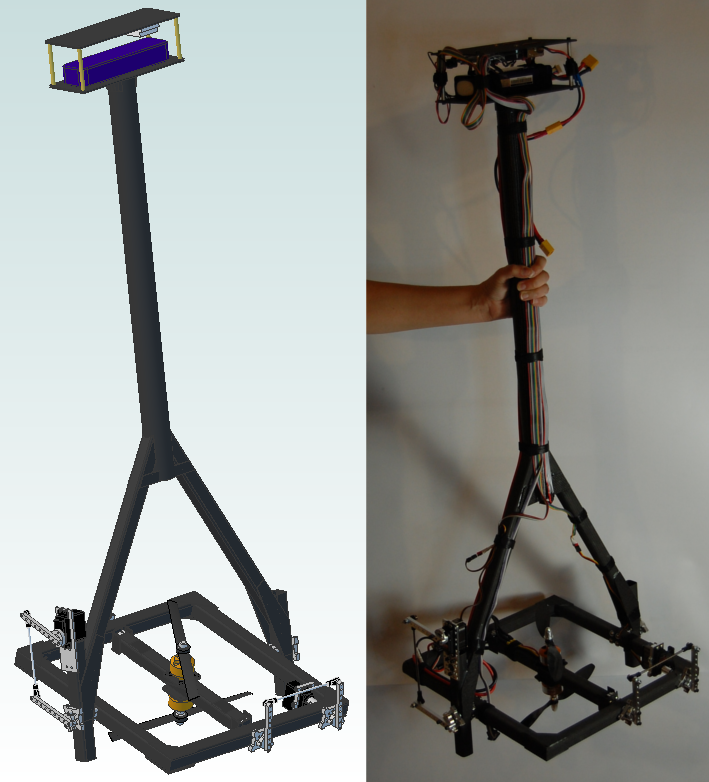
Overview
I started the GimbalBot project on April 30, 2014. GimbalBot is an open source unmanned aerial vehicle intended to explore a diverse range of topics including airframe design, aerodynamics, composites manufacturing, embedded systems, sensor fusion, and stability control. The craft combines characteristics from ball-balancing robots, rocket-stabilized landing vehicles, and single/dual-propeller drones that use actuated fins for attitude control.
GimbalBot's unique vectored fan design isn't meant to win any awards for efficiency, speed, maneuverability, cost, or other performance targets traditionally driven by business needs. Rather, I hope to share my own process of discovery and learning as I research and apply new (to me) concepts to a real-world project. If GimbalBot actually manages to get off the ground, I will be truly ecstatic.
System Design
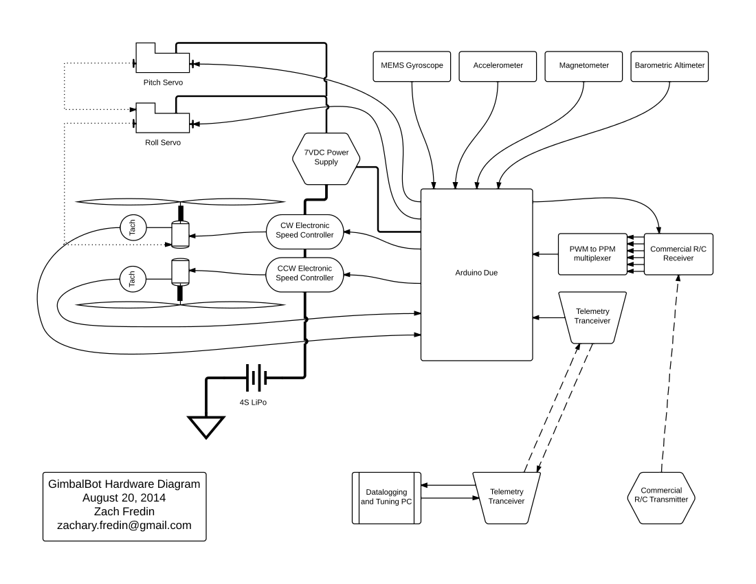 GimbalBot Hardware System Design (*.pdf)
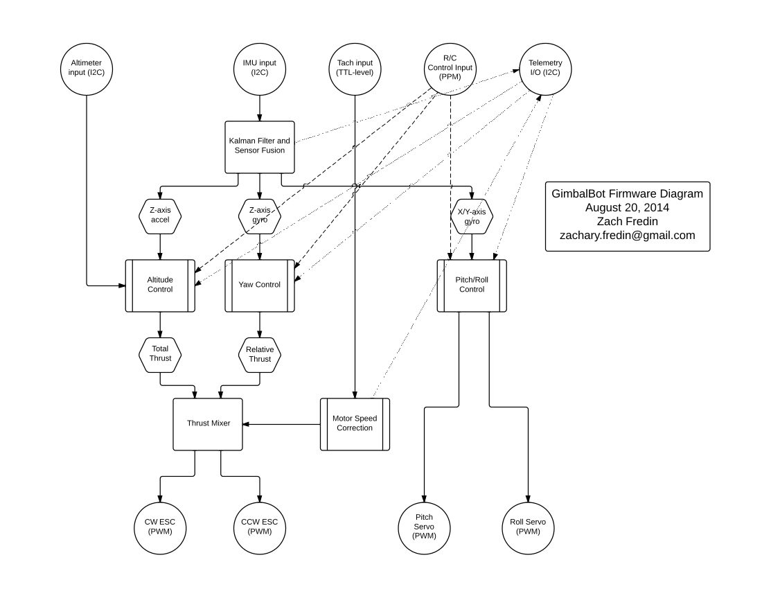 GimbalBot Firmware System Design (*.pdf)
Hackaday Prize Entry Video - Phase 1
Openness
GimbalBot is Open Hardware. Every aspect of this project is open, and this has been a fundamental design decision since day one. By sharing early concepts and models via a constant stream of project logs, I've been able to gather a vast number of invaluable suggestions that have been integral to the success of the project to date. I hope that by keeping my methods and decisions in the public eye, someone might learn from my mistakes and build on what I have learned from GimbalBot.
Connectivity
In its current iteration, GimbalBot isn't a connected device in that the craft does not directly interface with the Internet. However, the project does feature several local systems that are connected in various important ways.
Sensors
GimbalBot uses several sensors to keep tabs on its orientation in space, including a 3-axis accelerometer, a 3-axis MEMS gyroscope, a 3-axis magnetometer, and a barometric altimeter. All of these sensors communicate digitally with the Arduino Due over I2C and provide data at a rate of 50-100 Hz. I2C interpretation will be handled using the standard Arduino Wire library.
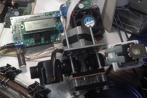
Actuation
The pitch ring servos and brushless motor electronic speed controllers (ESCs) are all off-the-shelf hobby R/C products, and as such use a standardized PWM interface for control. The standard Arduino Servo library will be used for encoding these signals.
Controls
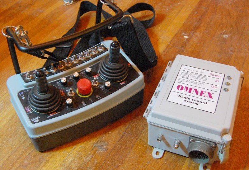
I'm reinventing the wheel enough with this project; for now, I'll be using a commercially available (and as-of-yet unselected) R/C setup with a dedicated receiver. While these systems often have sophisticated mixing and scaling features in the controllers, I plan to feed the raw receiver output through a PPM converter (to save on I/O lines) to the Arduino and deal with scaling issues in firmware. Since the RF protocols for these systems are generally proprietary, I'll keep the receiver interface open to ensure cross-compatibility with other radio platforms.
Telemetry
One of the most interesting parts of the GimbalBot project involves the control loops used for altitude, pitch, roll, and yaw control. In order to study and understand the interactions between these control systems and GimbalBot's various sensors, the craft will be fitted with a dedicated high-speed telemetry system for gathering sensor data and changing loop tuning parameters on the fly. While this system has not been designed in detail, I plan to use something like the XBee-PRO with a suitable computer interface.
License
I plan to release GimbalBot under the MIT license. This license will cover the on-board firmware, computer-side software, and all CAD part models, drawings, assemblies, and *.stl files. In other words, if you want to build a GimbalBot and sell it--please do. I still need to double check the licenses on the libraries I'm using for compatibility, so this may change in the near future; in any case, everything I do here will be entirely open and free for anyone to use without restriction.
Tools
In addition to a lot...
Read more »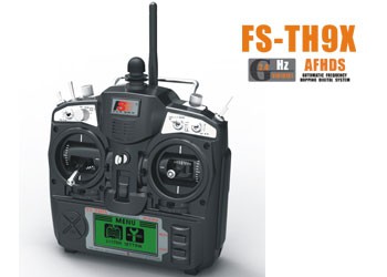


 James Newton
 Quinn
Quinn
Does this thing fly yet?