-
Oscillator LED Dimmer
12/29/2020 at 08:32 • 0 commentsThe circuit shown in this web page is based on the information presented in this article:
https://www.instructables.com/Oscillator-LED-Dimmer-1/
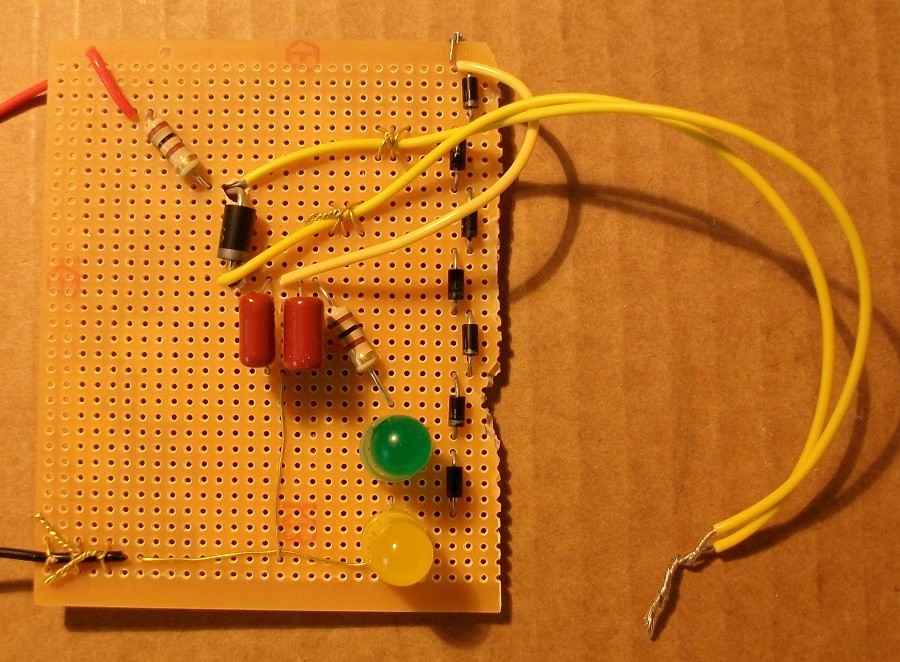
I modified the circuit to include Zener diode maximum LED current protection. I implemented the "Zener" diode with 7 typical silicon diodes because I already had those components:
VcapacitorMax = 7 * Vd = 7 * 0.7 V = 4.9 V
You can see the photo of my circuit here:
![]()
I added an additional LED (that is not needed):
Step 1: Design the Circuit
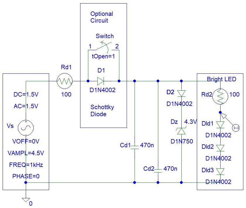
I drawn the circuit in PSpice student edition software:
![]()
The optional circuit diode should be a Schottky diode (preferably).
Calculate the maximum LED current:
Imax = (Vs - 2*Vled) / Rd2
= (5 V - 2 * 2 V) / 100 ohms
= 10 mA
Step 2: Simulations
Time domain:
![]()
Frequency domain:
![]()
Step 3: Testing
I tested the diode protection circuit (without Schottky - diode shorted):
I tested the diode protection circuit (with Schottky):
Step 4: Playing
I continues to play around with my circuit:
-
Ultrasonic Indicator
09/17/2020 at 02:44 • 0 commentsThis article presents an indicator that turns on the LEDs ON when an ultrasonic wave is detected with the ultrasonic sensor and amplified by the transistor amplifier circuit.
![]()
You can see my circuit working in this video:
I designed the circuit after reading those articles:
https://www.instructables.com/id/Ultrasonic-Alien/
https://www.instructables.com/id/Transistor-Vibrator-Kit/
Step 1: Design the Circuit
I drawn the circuit in PSpice simulation software to reduce drawing time:
![]()
Find the lower pass frequency of the transistor amplifiers
fl = 1 / (2*pi*(Rc1+Ri2)*Ci2) = 1 / (2*pi*(10,000 ohms + 1,000 ohms)*(470*10^-9 Farads))
= 30.7843216812 Hz
I increased the values of Rc1 and Rc2 resistors by factor of 10 (from 1 kohms to 10 kohms), hoping to increase the gain of the transistor amplifier. Usually the gain will increase, but lower collector biasing currents might also reduce the transistor current gain.
The Rf1 and Rf2 resistors need to be adjusted for each transistor because each transistor will have a slightly different current gain.
Step 2: Simulations
The yellow waveform is Vc1 and the pink waveform is Vc2:![]()
Thus you can see how high the gain of the Q2 transistor amplifier really is.
Step 3: Make the Circuit
I make this circuit without using a soldering iron.
![]()
Step 4: Testing
You can see that the ultrasonic circuit responds to clapping.
Ultrasonic wave reflection testing:
-
Noise Generator Toy
08/24/2020 at 08:28 • 0 commentsThis article shows a transistor noise generator circuit that I made.
The circuit also contains an optional LED indicator that converts noise AC voltage signals to LED light.
![]()
I thought of this idea after reading the following articles:
https://www.instructables.com/id/Ultrasonic-Alien/
https://www.instructables.com/id/Transistor-Microphone-Amplifier/
The circuit can be powered with two AA/AAA/C/D batteries. You can see the circuit working in the video:
Step 1: Design the Circuit
The circuit is designed with three fixed bias transistor amplifiers:
![]()
You can replace the two 470 uF capacitor pairs with just on 1000 uF capacitor.
The C4a, C4b and Rs4 components are optional. However, you might need those components if the power supply noise/oscillations are very high in amplitude. Eliminating those components will not increase the LED current and brightness. The high value of the C4a and C4b capacitors ensures that the transistor supply voltage does not fall below about 2.9 V.
The LED indicator can be made with only one LED. By reducing the Q4 transistor load (or increasing the Q4 transistor collector load resistance) you will also increase the circuit gain making the LED light brighter.
Step 2: Simulations
Transient simulations:
![]()
Transient simulations show that the LED current does increase about 1 mA. This is ten times less than 10 mA required maximum current for LEDs. However, I could not reduce the 100 ohm resistors out of fear of burning the LEDs. From the videos and photos you can see the maximum LED current must be at least about 7 mA.
Frequency domain simulations:
![]()
Frequency domain simulations show high bandwidth that might not be the case for real life general purpose transistors.
Step 3: Make the Circuit
I used only one capacitor for the Q3 transistor power supply oscillations filtering because there was no space on my matrix board.
![]()
Step 4: Testing
I connected my circuit to my bench top 3 V power supply powered from a mains 240 V socket.
I grounded the white wire (circuit input).
The graphs below show images from USB oscilloscope:
![]()
The graph above shows possible power supply oscillations with the generated noise.
I reduced the power supply voltage to about 2.7 volts and thus reduced the transistor biasing current and the current gain to obtain the graph below.
![]()
If you are using AA/AAA/C/D batteries it is not likely that the power supply voltage will be about about 2.9 V. Also, there is no 60 Hz/50 Hz power oscillations noise if you are using batteries instead of mains power supply.
You can see the fast blinking in this video.
My Pages


Projects I Like & Follow
 ril3y
ril3y marius.motea
 Blecky
 eDIY
eDIY Samuk
Samuk Szoftveres
 will.stevens
 youkito1991
 Bart//Bratke
 MaxBlack
 EK
EK schwarzrmsu
 Don Juan De Pyro
 Clovis Fritzen
FM radio with SI4703 and Arduino.
Android app as "remote control" bluetooth controlled
 Florin Nica
 Anas Raza Khan
 Marius Taciuc