-
Aviation Dosimetry in Africa
10/26/2023 at 22:37 • 0 commentsThe RPiRENA-based active dosimeter
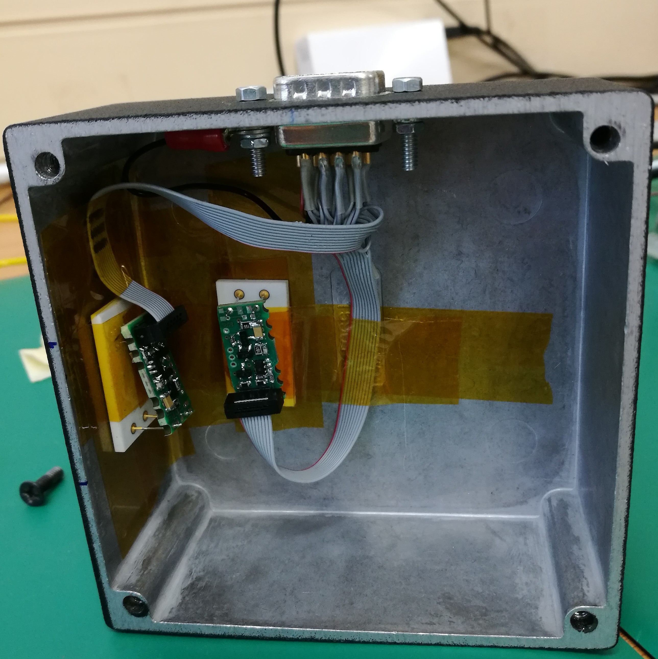
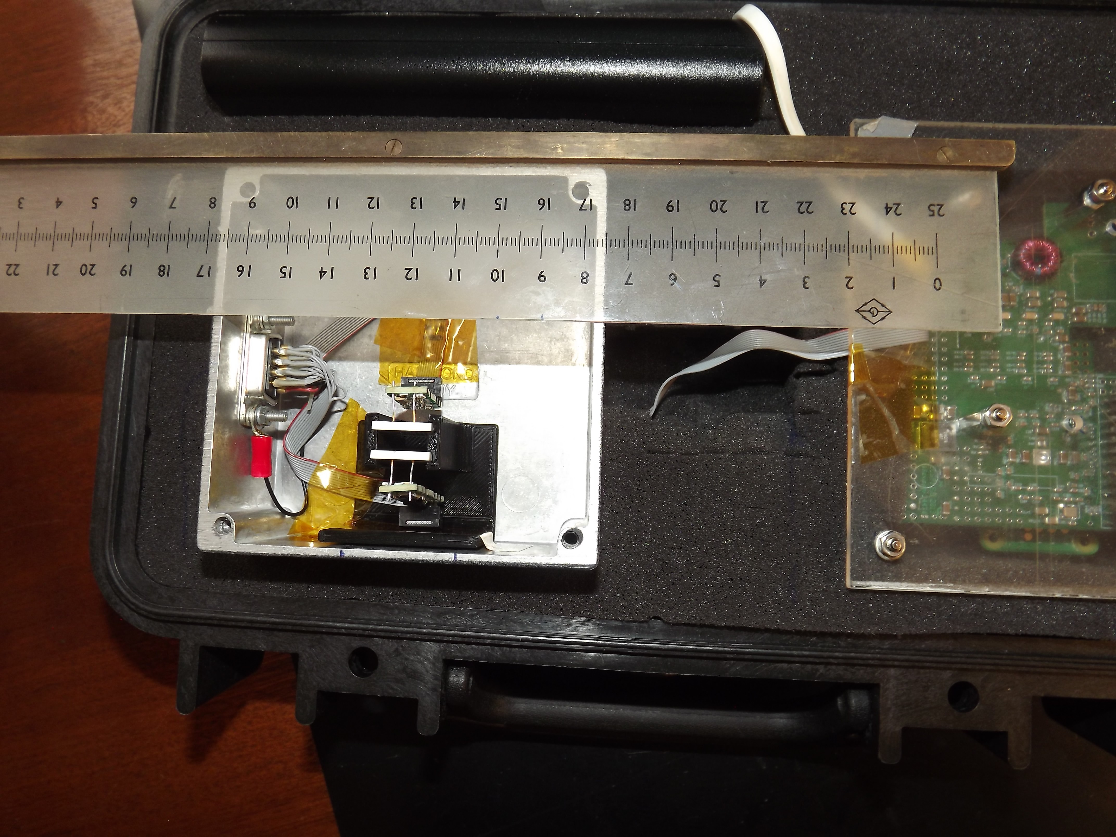
This particle detector works on the same principles as previously assembled dosimeter prototypes. Here, the detection system draws its power from the 3.3 V and 5 V GPIO (general purpose input output) pins from the connected Raspberry Pi (RPi) zero microcomputer, which is in turn powered via a rechargeable power bank.
The instrument draws about 0.4 A of power.
Data processing and storage are also performed on the RPi.
![]()
The silicone diodes (SDs) are connected to a reversed bias voltage of 45 V to fullydeplete the 300 lm thick diodes. When ionizing radiation interacts with an SD a short charge pulse is generated due to the separated charges. However, the charge pulse is too small to be sensed directly.
![]()
Therefore, the pulse is first sent to the amplifier section of the analog electronics.
Here, a charge-sensitive amplifier (CSA) amplifies the signals before the resulting pulse is shaped (by the pulse-height shaper, PHS), and then it is digitized by a 16-bit analog-to-digital converter (ADC).
A field programmable gate array (FPGA) is programmed to periodically sample the ADC signals and detect the peak voltage (i.e. the pulse height).
Since the pulse height is proportional to the energy deposited, the ADC value is proportional to the energy deposited in the detector after the appropriate calibrations are performed.
-
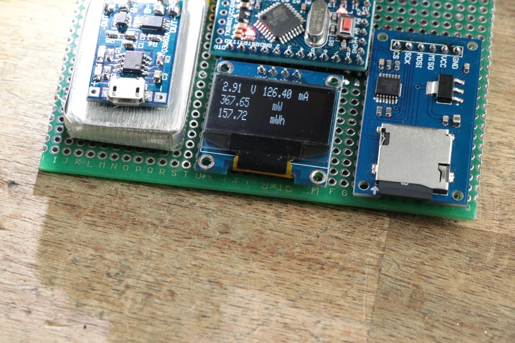
Make Your Own Power Meter/Logger
10/26/2023 at 14:44 • 0 comments1x LiPo Battery: https://s.click.aliexpress.com/e/_dZhZsnd
1x TP4056 Board: https://s.click.aliexpress.com/e/_dX8n0hp
1x Arduino Pro Mini: https://s.click.aliexpress.com/e/_d62ALdV
1x INA219 Board: https://s.click.aliexpress.com/e/_dUZvYoX
1x OLED LCD: https://s.click.aliexpress.com/e/_dWfFi0n
1x SD Card PCB: https://s.click.aliexpress.com/e/_dUy68bd
1x Switch: http://amzn.to/2gz9ZtW
eBay:
1x TP4056 Board: http://rover.ebay.com/rover/1/711-53200-19255-0/1?...
1x Arduino Pro Mini: http://rover.ebay.com/rover/1/711-53200-19255-0/1?...
1x INA219 Board: http://rover.ebay.com/rover/1/711-53200-19255-0/1?...
1x OLED LCD: http://rover.ebay.com/rover/1/711-53200-19255-0/1?...
1x SD Card PCB: http://rover.ebay.com/rover/1/711-53200-19255-0/1?...
1x Switch: http://rover.ebay.com/rover/1/711-53200-19255-0/1?...
Amazon.de:
1x LiPo Battery: http://amzn.to/2gM2vXB
1x TP4056 Board: http://amzn.to/2eUvMNO
1x Arduino Pro Mini: http://amzn.to/2g6Ujjr
1x INA219 Board: http://amzn.to/2gM5M9v
1x OLED LCD: http://amzn.to/2g6Q3Rd
1x SD Card PCB: http://amzn.to/2gM9Zdf
![]()
Arduino Nano Version
![]()
Now that your circuit is complete, it is time to upload the code. You can download it here. But don't forget to download and include the following libraries before uploading:
https://github.com/adafruit/Adafruit_INA219
https://github.com/adafruit/Adafruit_SSD1306
https://github.com/greiman/SdFat
![]()
-
Raspberry Pi Powered IOT Garden
10/26/2023 at 11:38 • 0 commentsOne of the primary objectives of this project was to be able to maintain the well-being of a garden using the power of the Internet of Things (IoT). With the versatility of the present tools and software, our planter is integrated with sensors that monitor the real-time status of the plants. We built a smartphone app that lets one access the data and take needed actions if necessary.
The design of our planter is scalable, low-cost, and easy to build, making it the perfect option to add greenery to one's terrace or backyard. The smart garden has proven to be more efficient in water consumption and facilitates maintenance and monitoring.
Follow on to learn how to make your very own database and app, by creating a garden that can be monitored by a click of a button!
Step 1: Overview of the IOT System
![Overview of the IOT System]()
![Overview of the IOT System]()
The IoT system functions through the following processes. A Raspberry Pi is used to relay useful information about the garden, such as luminosity, humidity, and moisture content in the soil from various sensors into a cloud database. Once the information is in the cloud, it can be accessed from anywhere using a smartphone app that we built. This process is reversible too, the user can send instructions, such as the state of the water pump, back to the garden which will execute the required commands.
The following are some of the key features of our garden :
- Real-time feedback of the garden's various sensors
- Database of the garden's health status
- Global monitoring and operating capacities
- Drip irrigation system
- App-controlled water system
- Automatic watering schedules
We decided to use Google's Firebase as the intermediary of our IOT system, to create our free cloud database. We then used MIT's App Inventor to create a smartphone application that is compatible with the Firebase database and the Raspberry Pi. It can also communicate with the database with the help of a free Python library.
Step 2: Materials Needed:
![Materials Needed:]()
![Materials Needed:]()
The materials needed to make the IoT planter can be easily found in local or online shops. The following list is a description of all the parts needed.
HARDWARE :
- 1" Pine Wood Plank - dimensions; 300cm x 10cm (as the wood will be outdoor, we would recommend treated wood)
- 1/4" Plywood - dimensions; 120cm by 80cm
- Tarpaulin Sheet - dimensions; 180cm x 275cm
- PVC Pipe - dimensions; length 30cm, Dia 2cm
- Surgical Tube - dimensions; 250cm
- Elbow Joint x 2
- Wood Screw x 30
ELECTRONICS :
- Raspberry Pi3 Model B
- Grove Pi + Sensor Shield
- 12V Solenoid Valve
- Humidity and Temperature Sensor (dht11)
- Moisture Sensor
- Luminosity Sensor
- Relay Module
- 12V Power Supply
Step 3: 3D Printed Parts
![3d Printed Parts]()
![3d Printed Parts]()
Various components that needed to be customized for this project were made with the help of 3D printing. The following list contains the complete list of parts and their printing specifications. All the STL files are provided in a folder attached above, allowing one to make their needed modifications if necessary.
- Pipe Joint x 1, 30% infill
- Nozzle Adaptor x 3, 30% infill
- Tube Plug x 3, 10% infill
- Hook x 2, 30% infill
- Sensor Mount x 1, 20% infill
- Valve Adaptor x 1, 20% infill
- Wiring Cover x 1, 20% infill
We used our Creality Ender 3 to print the parts, which took around 8 hours for the 12 parts.
Attachments
Step 4: The Plans
![The Plans]()
![The Plans]()
One is not restricted to the dimensions that we chose to make our planter, but attached above are all the details required to make the project. In the following steps, one can refer to these images to cut the wood.
Step 5: Building the Sides
![Building the Sides]()
To hold the plants we decided to make a planter structure out of wood. The inner dimensions of our box are 70cm by 50cm with a height of 10cm. We used pine wood planks to build the sides.
Using a circular saw we cut the four pieces to length (dimensions attached above). We drilled...
Read more »
My Pages


Things I've Built
Muon Detector
Pocket-sized muon detector for science education purposes
ESP32 Weather Station
DIY Weather Station Control Board using off-the-shelf components
GSM Data Logger
We designed a GSM data logger to connect 4 pressure transducers. The client needed to take measurements underwater in a mechanical system.
Projects I Like & Follow
 Hugo Melder
 James Dietz
 Zapp
Zapp Subhajit
 Andrea Console
 deqing
 agp.cooper
 AIRPOCKET
 Vedran
 Lithium ION
 RT-Thread IoT OS
 Adrián Saúl Reibán
Share this profile
ShareBits


IoT-devices, LLC
wrote 10/27/2023 at 10:45
•
point
Thank you for your interest in @IoT-devices, LLC and for following our projects, especially the #GGreg20_V3 Ionizing Radiation Detector!
I found the project very interesting. Maybe we should collab on a project later on?