Close
0%
0%

SpiderWing

Spider robot powered by Adafruit Feather boards and CircuitPython.

Similar projects worth following

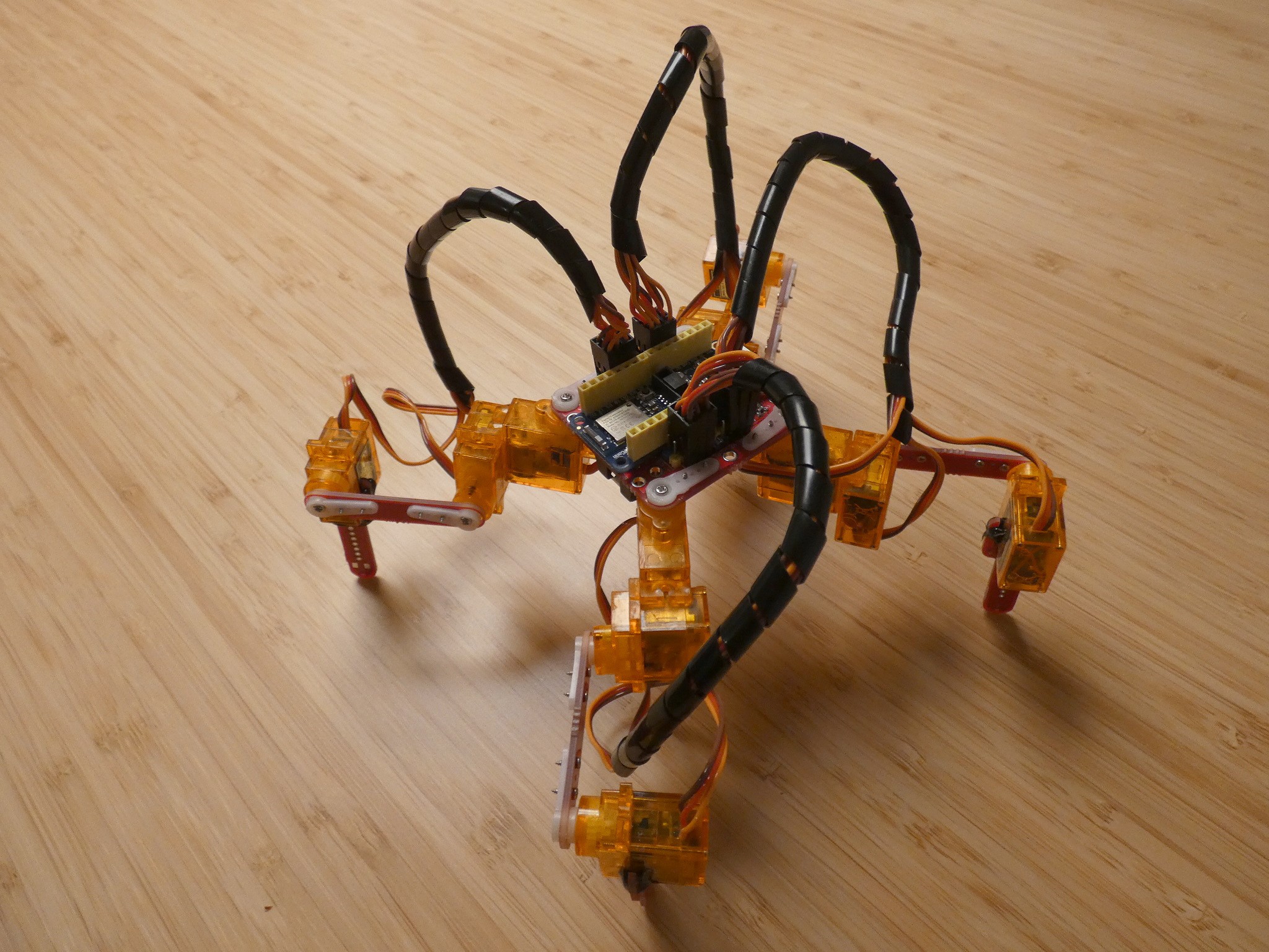
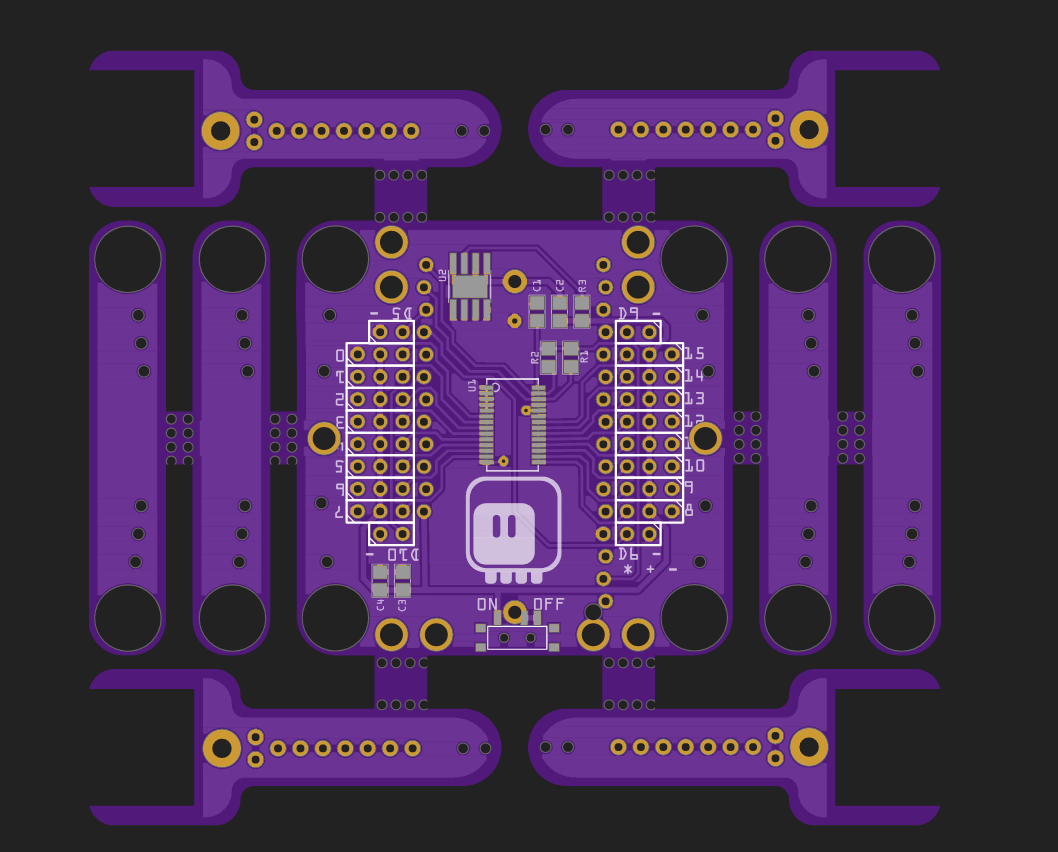
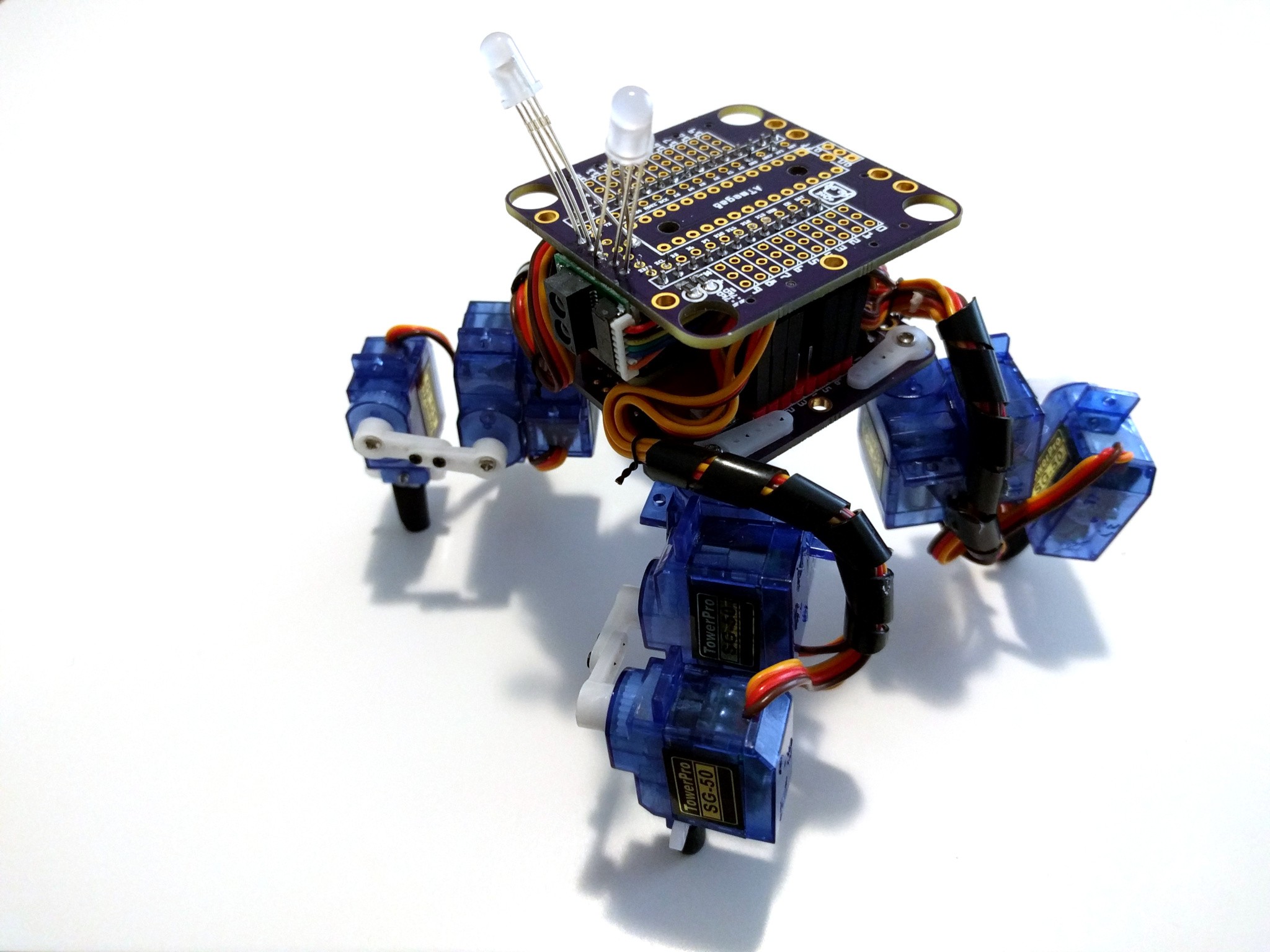
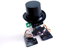
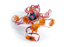
This is the successor of the #Tote robot, and its small family (#Tote Zero, #Tote HaD, #D1 Mini Tote). Tote itself was focused mostly on affordability, ease of assembly and extensibility — and I think that it achieved those goals relatively well. However, it turns out that physically building the robot and programming the first gait is just the tip of the iceberg. We need something a little more powerful than a simple Arduino, and something much easier to program and test. The SpiderWing builds on top of Tote, but focuses more on the ease of programming and reliability. It uses slightly more expensive parts (Adafruit Feather boards, SG92R servos) to be more reliable and easier to reproduce exactly (whereas every Tote is slightly different from all the others). It will also use advanced sensors, such as the time-of-flight distance sensors or the IMU sensors with built-in fusion algorithms, in order to get better and more consistent results.

Of course the ultimate goal remains the same — to bring walking robots into our homes and hopefully crowd-source their development, so that they become reliable and cheap enough to be generally useful.

spiderwing.fzz

Fritzing PCB design and schematic

x-fritzing-fzz - 156.84 kB - 12/31/2019 at 18:28

Download

  • 1 × Adafruit Feather supporting CircuitPython
  • 1 × 3.7V 1S LiPO battery
  • 1 × SPDT switch
  • 12 × SG92R Microservo
  • 24 × M1.2x4 screws

View all 10 components

  • It's Alive (Again)

    deʃhipu12/31/2019 at 18:28 0 comments

    It took me a while to re-assemble, re-connect and re-calibrate all the legs with the new PCB, but today the robot is again standing on its own. I was a bit worried that the battery protection circuit would interfere with the servos drawing their share of the current, but it seems to be perfectly fine. I was putting off connecting the servos for a bit, because I didn't have the male pin headers soldered, and I was thinking that perhaps I should cut the servo wires and solder them directly to the underside of the PCB. But then I decided to leave them long for now, for easier hacking. I can always make a "tidy" version of this robot later.

    I have replaced the old HUZZAH feather with the new NRF52840 feather, because the CircuitPython is no longer supported on the ESP8266, and there is some very exciting progresss on bluetooth support on the NRF, and that would be perfect for controlling this robot. For now I just use the REPL over the USB cable, though, still using the old gait code — that's one of the parts that still needs work.

    There are also still no switches at the ends of the legs — they are ordered, but Christmas is not the time of fast packages. At the very least they should let the robot avoid falling off the table.

    As you can see, since I'm using stacking headers with all my feathers, there is room for adding modules on top of the robot. It could be a prototyping board with some sensors, or one of the other featherwings with displays, LEDs, speakers, etc. — it would even work very well with the #Gesture FeatherWing, controlled by gestures — if I ever get that to work.

  • Bodgetty Bodge

    deʃhipu12/16/2019 at 22:49 0 comments

    The PCBs arrived today, so time for some testing. I didn't have any PCA9685 left, so I had to remove it from one of my old #Servo Breakout for WeMos D1 Mini boards. With all the parts in place, time for some test:

    And nope, the Feather doesn't get enough power. That's weird. Let's check the footprint for that battery protection chip again, shall we? Ah-ha! Here you go, I switched two pins, of course:

    Fortunately the bodge is quite easy here. Of course I already fixed the mistake in the PCB design files. With this small change, everything is working as intended.

    It took some time to assemble the legs, but nothing revolutionary there. I have all the physical parts assembled, but no time for tuning and programming it, so it will probably wait for the holidays.

  • Batteries! Why Doesn't Anybody Think About the Batteries?

    deʃhipu12/08/2019 at 18:52 0 comments

    Today I decided that the new PCB design was lying on the disk long enough, and that it's time to order it. But then, when I opened it in Fritzing, I decided to work on it a little bit more and add an important feature: battery protection.

    You see, the batteries that Adafruit sells already come with the protection circuit, so the battery handling circuit on the feathers doesn't include it, but those batteries are too small for all those servos (and also kinda difficult to attach properly), so I'm instead using a bare 16340 battery (it's half of a 18650, if you were wondering). But that means no protection, and that means you can damage your batteries if you are forgetful. On the previous models I had software monitoring of the battery status, but that's not as reliable.

    So I decided to go on and add a battery protection chip. Looking through my drawers, I found a HT3062E, which, judging by the Chinese datasheet, should allow up to 8A of current — that should be plenty for those tiny little servos. It comes in an ESPO8 package, so it was easy enough to add it to the PCB design:

    I had to remove the prototyping area at the front of the robot to make room for it (it had to be close to the minus side of the battery), but most Feathers have a prototyping area of their own on that side, so that shouldn't be too much of a problem.

    I also made the pin header holes for the Feather staggered, so you should be able to save some height of the robot by plugging the board directly, without the need for female pin headers.

    I ordered the boards from DirtyPCBs, because they are the only ones who don't care how many "designs" there are on a single PCB (most fabs will treat all the leg parts as separate designs and demand additional fees for them, for some reason).

  • New PCB Design

    deʃhipu11/03/2019 at 18:23 1 comment

    As mentioned, it's time to modernize this design a little bit. So first of all, I added the PCB legs from #D1 Mini Tote, and also added footprints for contact switches at the ends of those legs. Then I switched all parts (except for headers) to SMD, because that's usually cheaper and easier to fabricate. Finally, we have some additional headers for connecting those foot switches to the Feather's pins.

    The shield remains relatively simple — just a PCA9685 for servo control, and a battery holder with a power switch, and a couple of extra capacitors. The whole thing fits in 10x10cm, so you should be able to order it easily, though some fabs might complain about "multiple projects" in the design.

  • Time for a Refresh

    deʃhipu11/02/2019 at 21:59 0 comments

    I left this project be, and focused more on the #Kubik M0 and #D1 Mini Tote projects, but it's time to revisit it, and bring back the improvements from those two projects.

  • Repository and License

    deʃhipu07/23/2017 at 18:39 0 comments

    I just realized that I never linked the repository with the code and design files in here. I now fixed that mistake — you can find the link on the right, under project's links.

    I also added a license file to the repository, so that people can actually build on top of all this without having to ask me every time. I've chosen Creative Commons license, because it's a physical object, not just software, and the software licenses didn't seem appropriate.

  • Proper Crawl

    deʃhipu07/23/2017 at 18:12 1 comment

    I went over the large SpiderWing and shortened its legs back to what #Tote has. The idea to make coxas much longer sounded great — you get longer steps and thus higher speed, without actually increasing the load on the servos (since coxas only move in the horizontal plane anyways). However, doing that also changes the reachable area of the leg from a shape similar to a pizza slice, to one that looks more like a slice of a pineapple — with the center removed. Do it too much, and you can no longer draw a nice long straight line inside it — meaning the robot's step has to be small.

    So I shortened the coxas, but left the tibias long — that actually increases the load, but the servos can handle it. Once the changes were done, I had to replace a few faulty servos, that were catching for some reason. After that, finding the set of parameters that would let the robot move at a decent speed was much easier:

    Next on the list is smoothing all those movements. Right now they are very jerky, so much so that the legs tend to slip on the floor. Unfortunately, I will probably need to rewrite most of the gait code to do that.

  • Status Update

    deʃhipu07/19/2017 at 10:30 0 comments

    The mini-crab version of the robot is as good as it's going to get -- I'm going to leave it as it is for a while, to have something to show at all the conferences and fairs.

    The bigger spider robot still needs work. I will probably need to shorten its coxas, as this configuration was an experiment and doesn't seem to work that great. I am happy about the longer tibias though. I will probably replace the ESP8266 Feather with a ESP32 one, for more processing power and — hopefully — smoother movement. I'm more or less happy with the PCB, so I don't think there will be more versions of it. I will however need to make some sensor shields to stack on top.

    The main thing that requires work, as usual, is the documentation.

    I also have plans to program the #PewPew FeatherWing board to act as a controller for this robot, but since both are still in development, it may take some time.

  • Smartening Up

    deʃhipu05/15/2017 at 19:47 0 comments

    I got the gait code to work on the small crab robot -- actually it only needed some adjustments for the smaller legs. I'm a bit disappointed about how slow the code runs on the M0 -- I didn't even need to add delays for the servos, the calculations take enough time for them to move into place. Oh well. That means the gait is still jerky (because I couldn't do the continuous servo updates), but it works fine.

    Then I worked a little bit on the robot's "intelligence". Right now it only has only one sensor, the distance sensor in front. So its behavior is as follows:

    • If the distance sensor doesn't detect anything, or the thing detected is too far away, just stand there and scan from left to right and then from right to left. Eye color blue.
    • If something is detected far away, walk towards it. Eye color green.
    • If something is detected close, stop. Eye color purple. Wait for one second, then check if it moved. If it did, wait again. If it didn't, look right and left, see where you have more room, and turn 60° in that direction. Eye color cyan.
    • If something is very close, walk backwards. Eye color red.

    And that's it. I also added exception catching, so when the legs get tangled into an impossible position (that happens sometimes), they are moved into their home positions, and then the program resumes.

    This procedure gives the robot a nice behavior. It will walk towards things to examine them, and follow people, but if the things don't move, it will get bored with them and walk away, looking for other interesting things.

    I'm considering adding one more state, for when it gets bored with scanning -- perhaps it could just shut down and go to sleep then.

  • Sensor and Cable Management

    deʃhipu05/14/2017 at 18:51 0 comments

    I'm slowly porting all my robot code to CircuitPython for the little crab robot, and I got as far as body kinematics before I ran out of memory on the Feather M0, so next step is some optimizations.

    I also decided to put a distance sensor on this little guy, so that it can react to the environment -- since it doesn't have wireless connectivity, I can't make it just a remote controlled drone (and I don't want to).

    So I finally sat down and ported that Arduino driver for the VL53L0X sensor to MicroPython. Well, mostly ported -- there are still some parts that I need to implement, but it already does some readings. The code is at https://bitbucket.org/thesheep/micropython-vl53l0x but it's definitely too big to fit on the M0. So I decided to look for another sensor, preferably with I²C interface, and I found the SHARP GP2Y0E03 in my drawers -- the same sensor that #µBob biped robot uses right now. I quickly wrote a simple driver for CircuitPython for it -- the code is at https://bitbucket.org/thesheep/circuitpython-gp2y0e03 -- and I attached the sensor to the robot:

    You can see I also arranged the cables neatly, and added the rubber socks on the legs.

    Even though I had a ready library for the sensor, getting it to work took some time. You see, the PCA9685 chip that I'm using here for controlling the servos uses two I²C addresses: 0x40 and 0x70 (one for the individual chip, and one for a roll-call for all chips on the bus). But the GP2Y0E03 sensor also uses address 0x40 by default. I could mess with the PCB, solder some wires to the address pins od the PCA9685 and make it use a different address (I think I will in the next version of the PCB), but a quicker route was to change the sensor's address -- you do that by burning e-fuses on it to specify the new address. The procedure is a bit complex, but there is a ready Arduino sketch that does it for you, so I gave it a try. Without much thinking I changed the address to the 0xE0, which was the default in that sketch.

    Wait, aren't I²C addresses only 7-bit? Where did 0xE0 come from? Well, that's the 8-bit notation, including the read/write bit. To get the 7-bit address you need to shift it right by one.

    I tested the sensor with the changed address, and it works beautifully. Now, time to put on the robot and make it do some things. But wait, it stops working on the robot, just returns 0 all the time. Wait a moment, what is 0xE0 shifter right by one bit? Isn't it 0x70, the other address my servo driver uses? Argh!

    Fortunately, I had a second GP2Y0E03 sensor in my stock, so I changed the address in another one (this time paying more attention) and everything works perfectly now.

    Now I only need to rewrite all this code into as few functions as possible, to make it all fit in there.

View all 11 project logs

  • 1
    Mechanical Assembly

    For mechanical assembly, follow the instructions at http://tote.readthedocs.io/en/latest/assembly_v5.html#legs

  • 2
    Electronics

    Solder the headers, the PWM chip and the two resistors onto the PCB. Add the power switch and the battery holder.

  • 3
    Programming

    Copy the python files from the project's repository onto your feather board.

View all 4 instructions

Enjoy this project?

Share

Discussions

kkerim.arkan wrote 09/23/2021 at 09:30 point

Did to try to integrate the wire in this spider project? I want to test it for Spider Solitaire game that hosted on Live Website. 

  Are you sure? yes | no

davedarko wrote 02/19/2017 at 09:11 point

when you find the time, could you talk a bit about the SG92R vs. the normal SG90 or the MG90S?

  Are you sure? yes | no

davedarko wrote 02/19/2017 at 10:18 point

you know what, I should google that first, someone must have blogged about this already :D

  Are you sure? yes | no

ActualDragon wrote 02/19/2017 at 21:41 point

wow, DaveDarko?!?! It's usually me who gets yelled at for that

  Are you sure? yes | no

davedarko wrote 02/19/2017 at 22:12 point

@ActualDragon but, but I noticed it myself, nobody was yelling. Isn't that different? 

  Are you sure? yes | no

ActualDragon wrote 02/19/2017 at 22:43 point

same diff you know what i mean

  Are you sure? yes | no

Similar Projects

Does this project spark your interest?

Become a member to follow this project and never miss any updates