 Marius Taciuc
Challenge:
I'm a former Romanian HW engineer and I recently moved to Papua New Guinea for a few years. While being involved here in some technical works, I had the opportunity to travel a lot into the remote jungle sides of this country. In the rural areas, people are trying to develop better living conditions here and to begin to use some small solar panels and some lead acid batteries to power a few lights and maybe in some cases, charge their mobile phones. The technology is many times too expensive for these places and people are ending up connecting their refurbished solar panels directly to some old car batteries. This dangerous practice for a desperate cause to light up some 3W light bulbs at night, leads many times to setting the batteries or the houses on fire.
Solution:
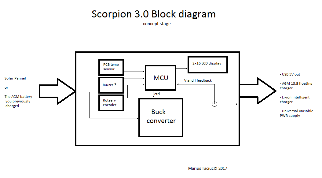
A fairly technical and good solution would be to design a low price adjustable and multi-purpose DC to DC converter power supply that is very simple to use. My idea is to have a small 40W custom built solar charger that has the possibility of converting into a battery to device power supply that can allow multiple voltages at it's output. This multi-purpose tool could have an AGM battery charger implemented in it's menu and it could also have a Li-ion battery charger.
The aim would be to create this tool for the masses at a low price and keep it under 10$ so the people of these places could afford to buy it.
![]() Potential benefits:
Potential benefits:
The potential benefits of having such a device are enormous. Some of them would be:
- The possibility of having a very cheap solar charger for some AGM batteries between 7Ah and 55aH (in some cases)
- The possibility of having a mobile phone charger. In some areas, there is mobile phone signal, but people don’t have the possibility of charging mobile phones.
- The possibility of having access to other devices as mp3 players and audiobooks.
- Access to radio (local news, information and other media content)(where local radio stations are available)
- Small indoor illumination system.
- Increasing the chance of access to education having stated all the above benefits.
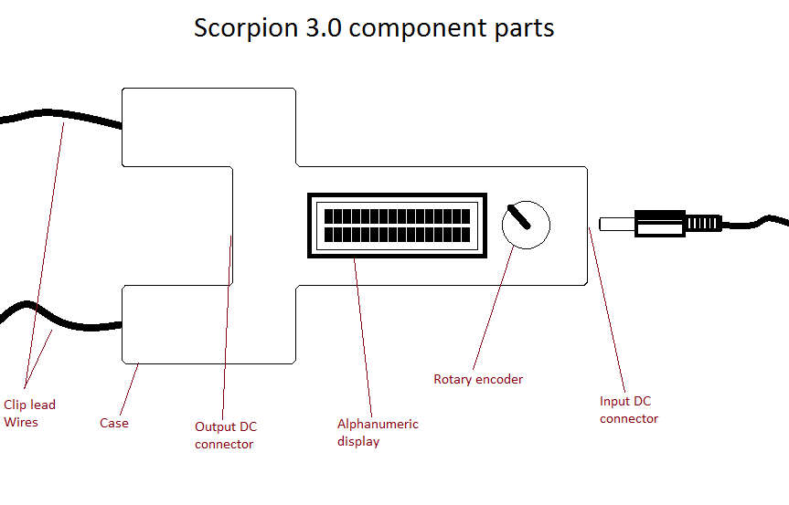
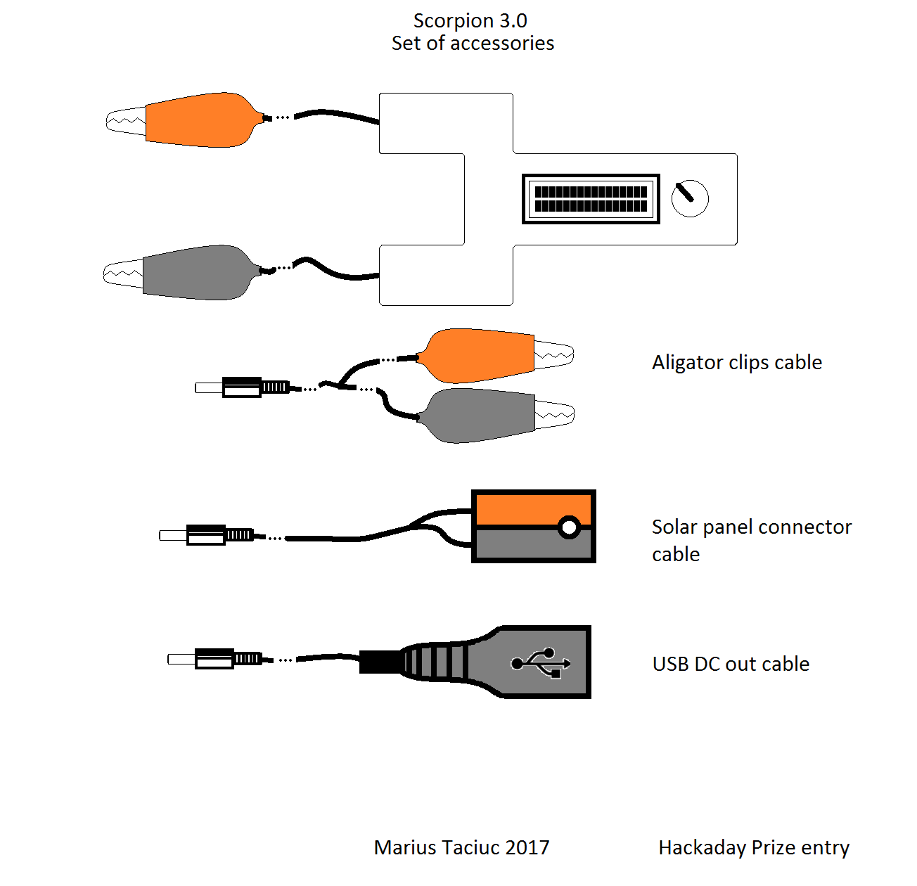
![]() Tools to be implemented within this device:
Tools to be implemented within this device:
- Solar USB charger (SP voltages up to 40V)
Aiming to build something that is able to convert the voltage of the solar panel (SP) down to 5V for directly charging a mobile phone
- Solar AGM 12V battery charger (maximum charging current of @ 3A)
Planning to add a sub menu in the software that will be able to act like an AGM solar charger. The Scorpion 3.0 should be able to provide the floating voltages of 13.6V - 13.8V
- Intelligent Solar Li-ion battery charger (configurable number of cells)
Planning to be able to set from the menu a Li-ion battery charger. This function could allow the user to configure the number of cells or the nominal voltage of the battery they want to charge and to be able to input the C parameter of the battery. Scorpion 3.0 should know what to do with these numbers.
- USB charger using the power stored in the batteries by connecting the device in reverse
Scorpion 3.0 should be able to support other voltage (power) input sources like an AGM battery. In these conditions, it should be able to still function as an USB charger and as an universal variable power supply
- Universal variable power supply that can be connected either to the SP or the charged battery
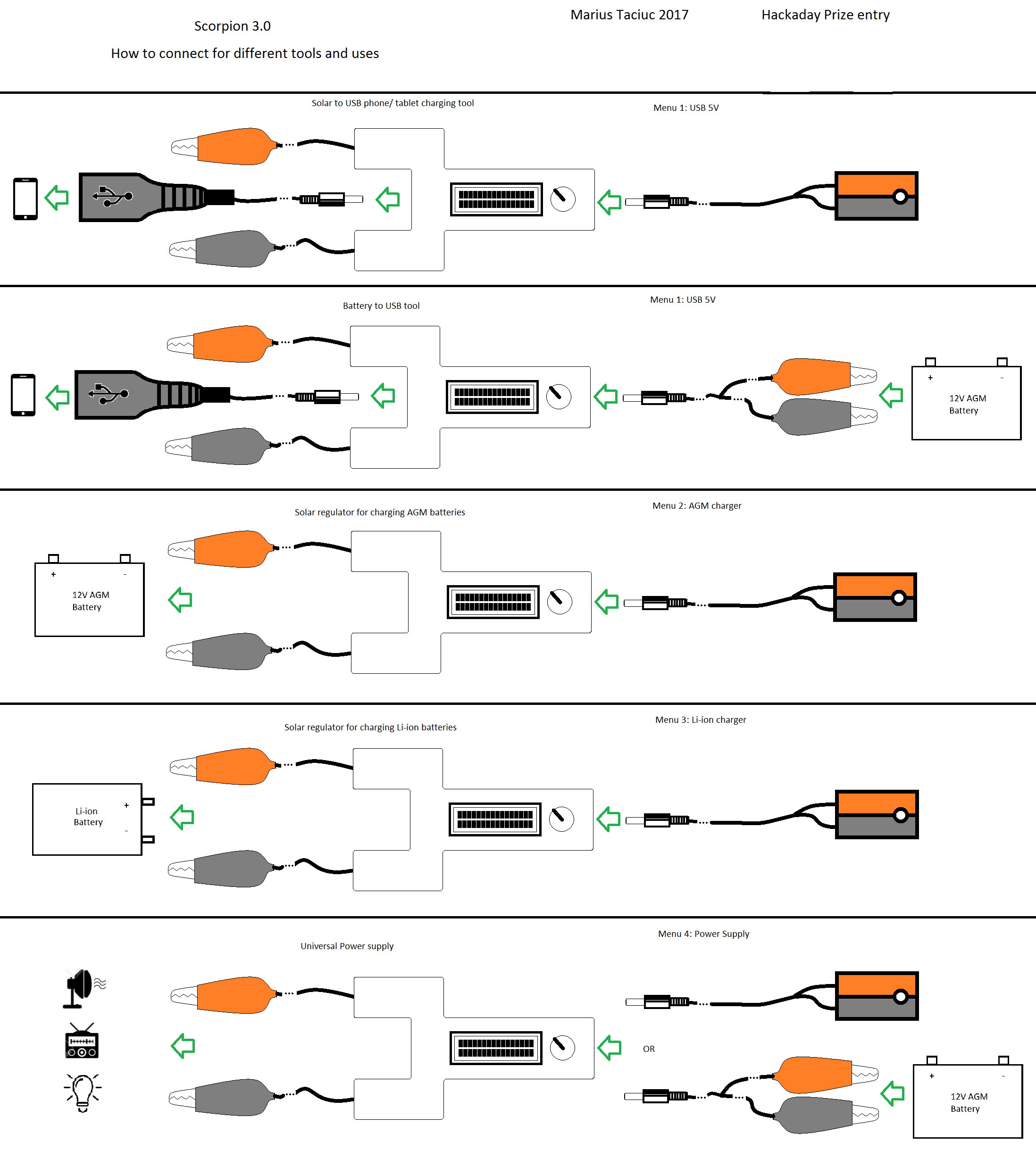
![]() This leaves me with the need of implementing four sub-menus in the graphical interface of the display, as follows:
This leaves me with the need of implementing four sub-menus in the graphical interface of the display, as follows:
- Power supply
- AGM charger
- Li-ion charger
- USB 5V
Power concerns, humidity concerns and …more concerns about the Buck idea.
I realize that this design must be water proof. In these areas, the measured humidity exceeds 80% almost everyday. I realize that having a piece of electronic - whatever thing - inside of a coconut leaves roof house, can lead to water being splashed over the case. After I will have a mature design, I plan to cover the PBG with a varnish...
Read more »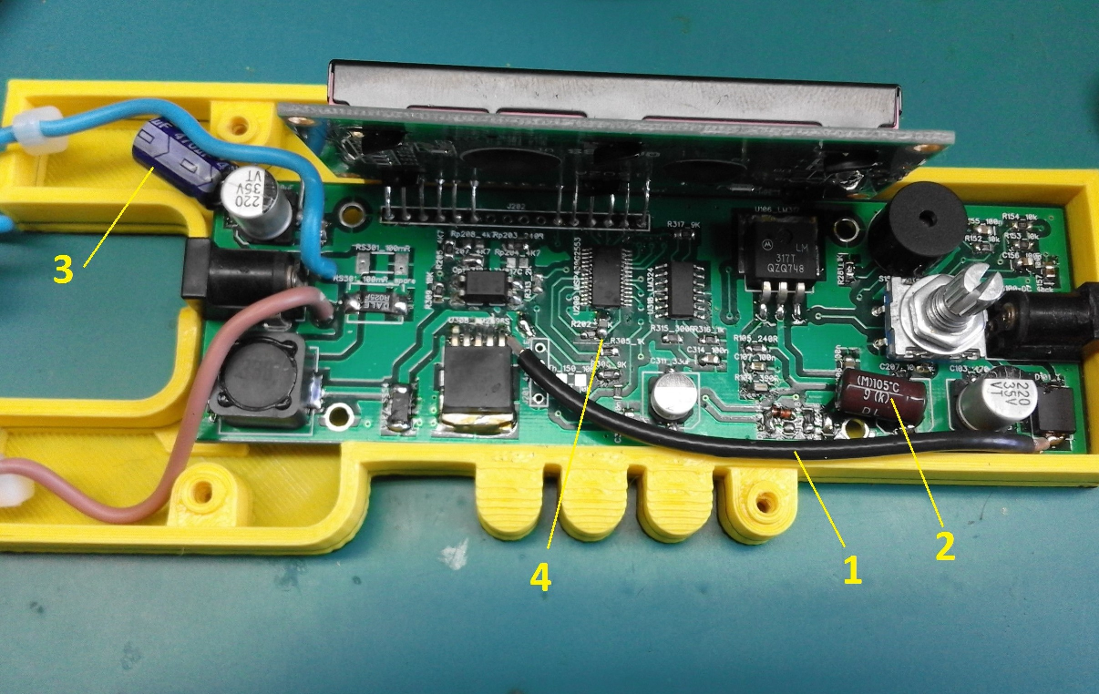


 Space Buck
 jaromir.sukuba
 Arthur Admiraal
 Lucy Fauth
Great post! Insightful and engaging content. Keep up the excellent work. If you want to land your dream job now, visit: https://jobsearchlive.com/jobs