 Bob Baddeley
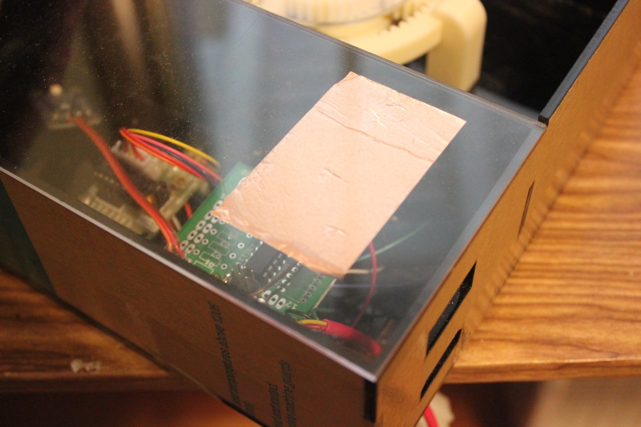
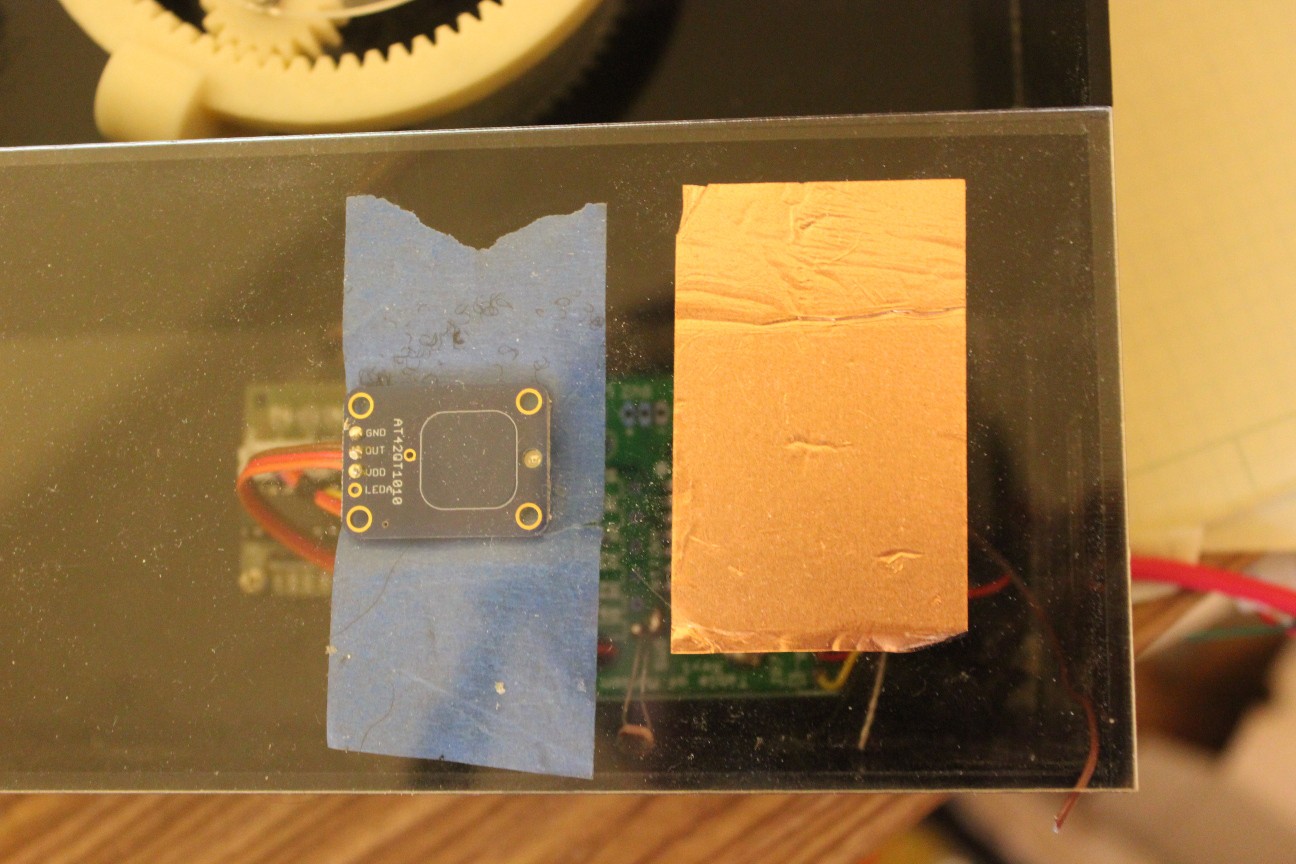
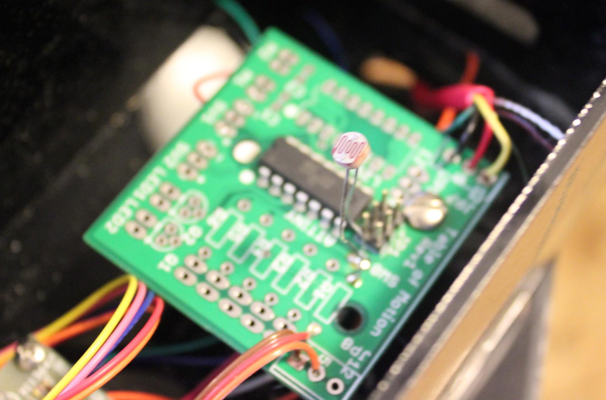
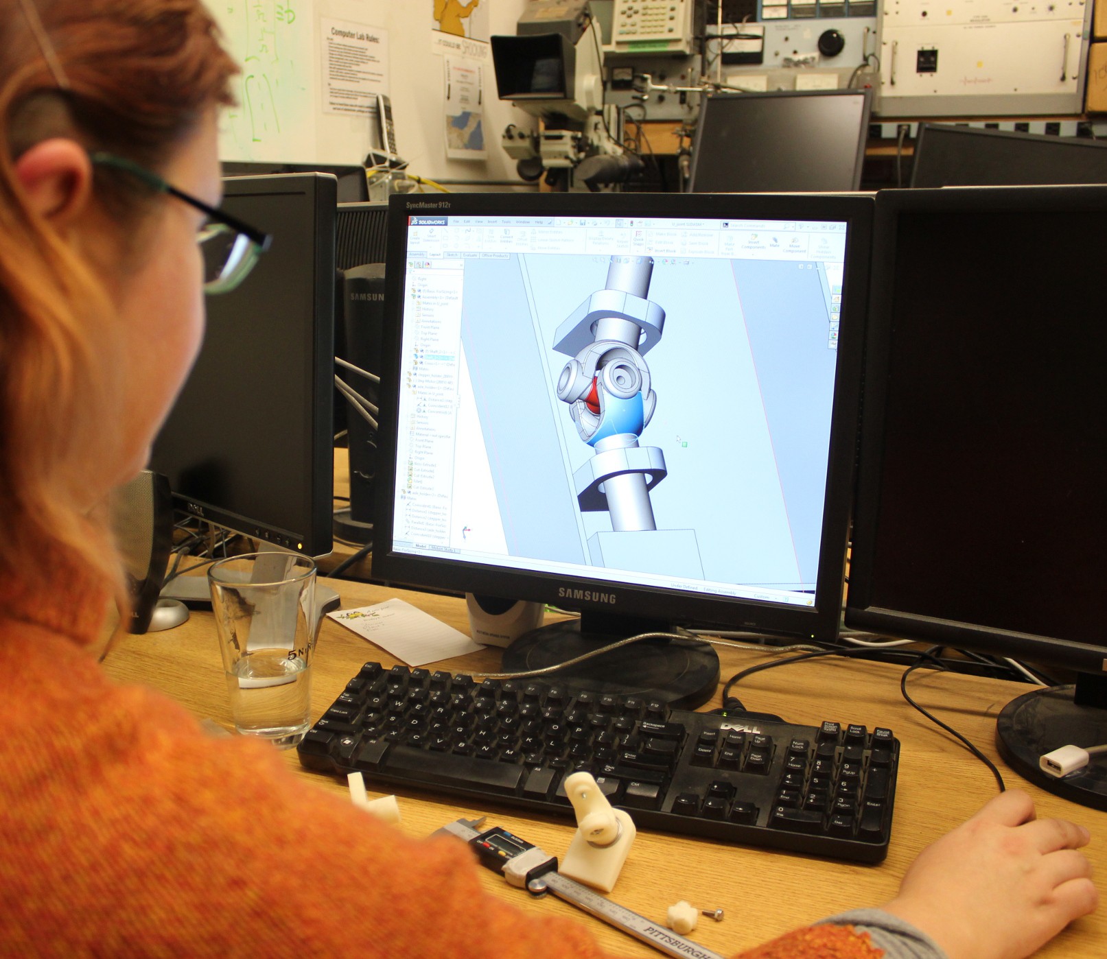
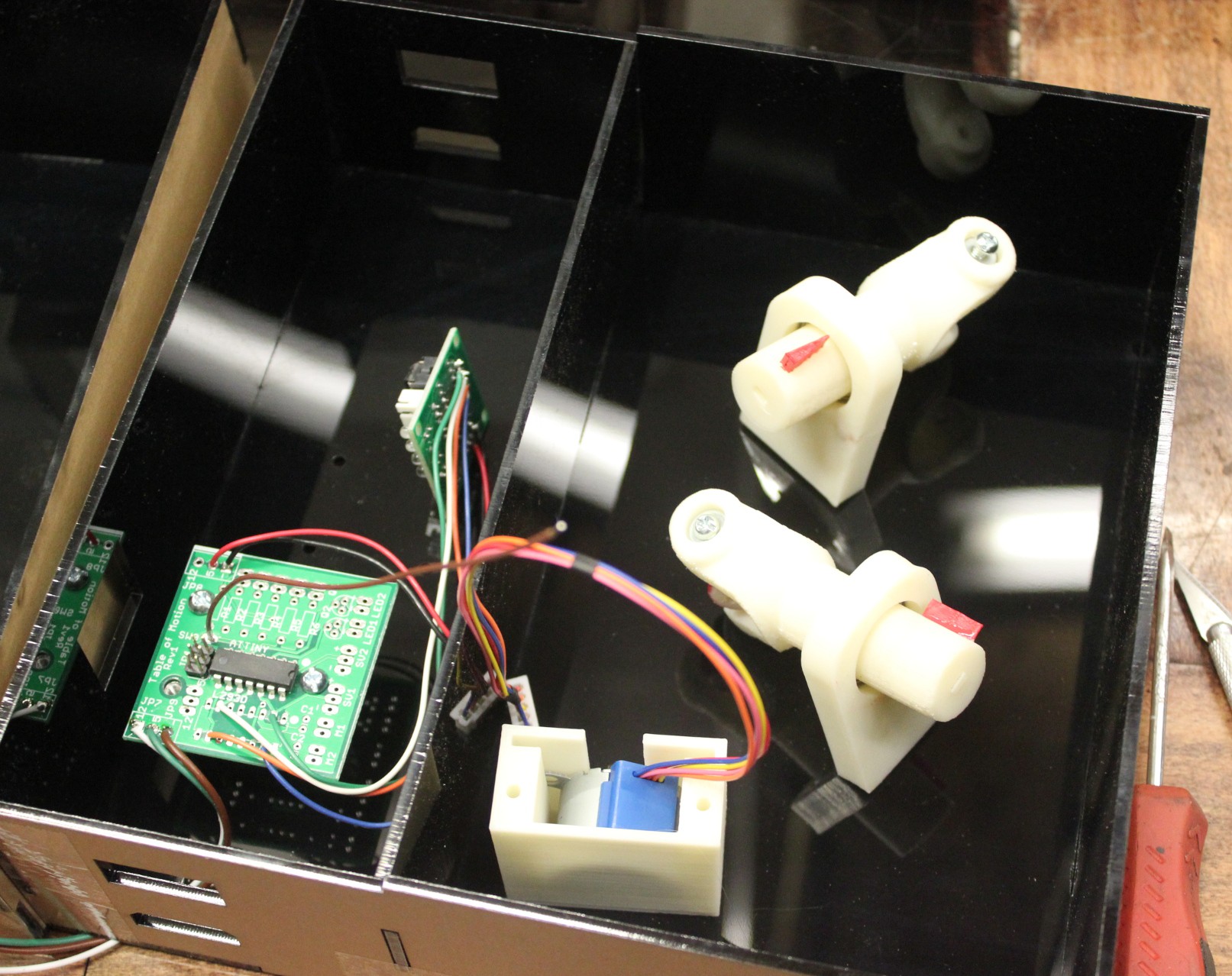
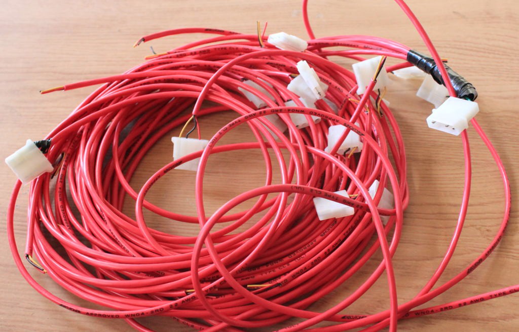
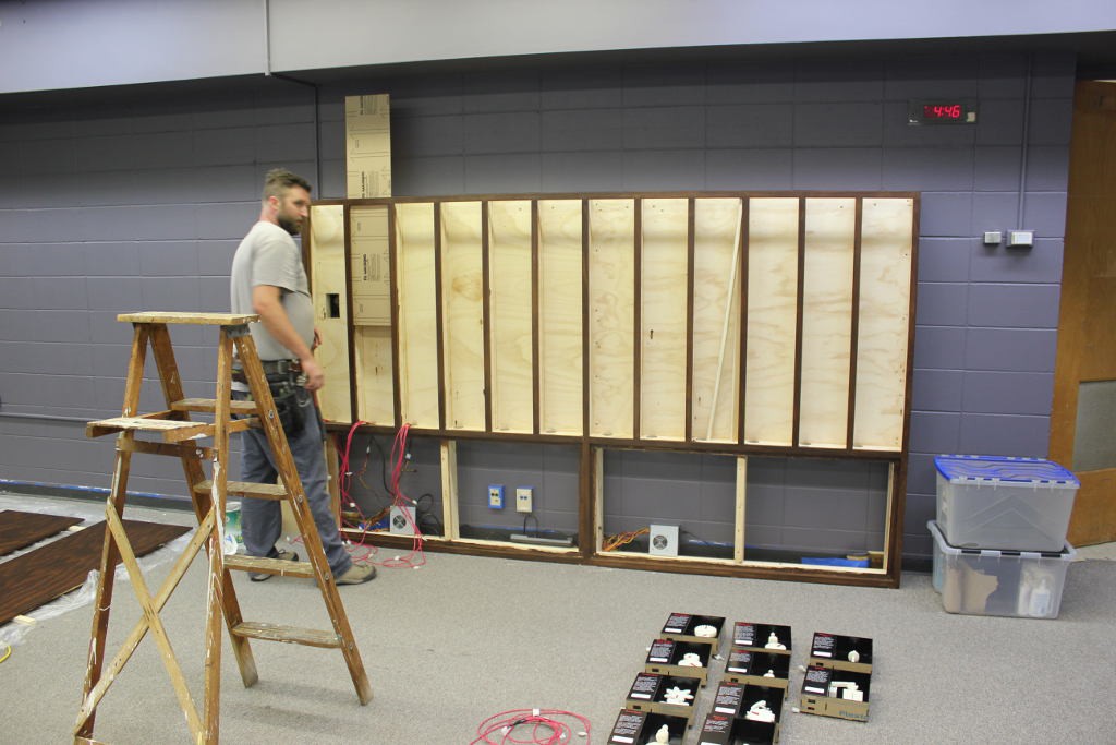
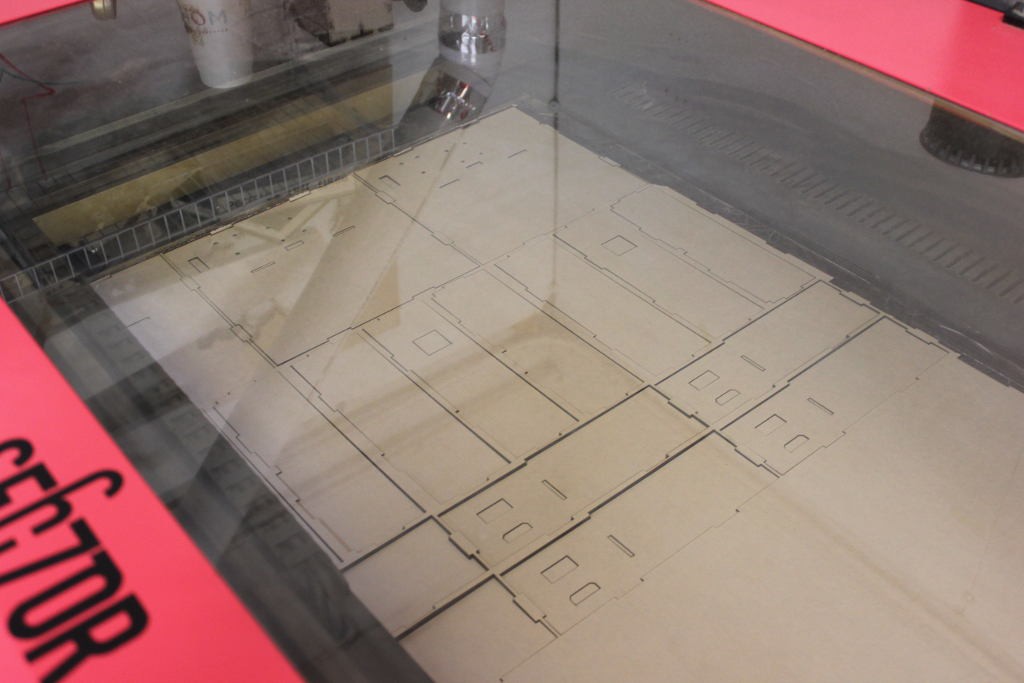
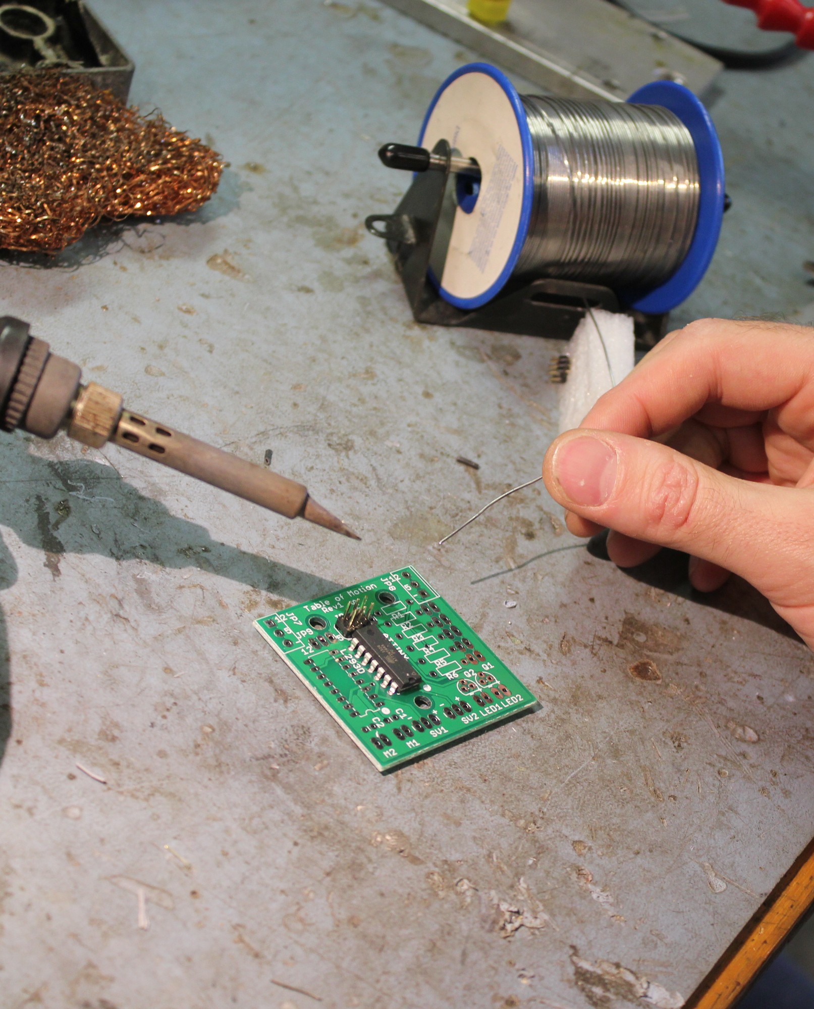
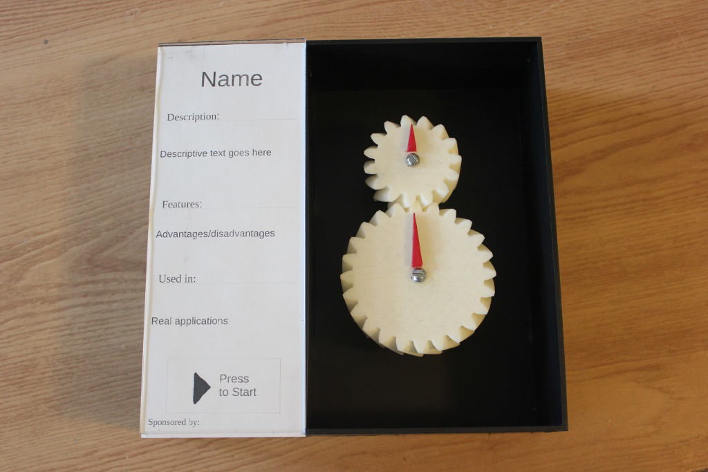
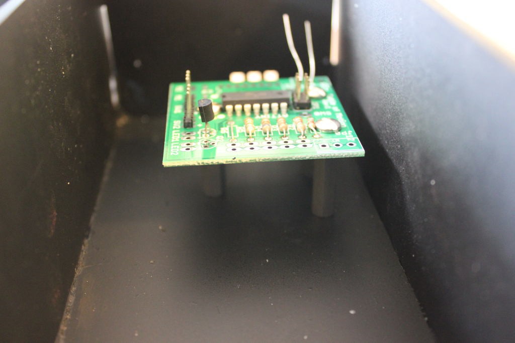
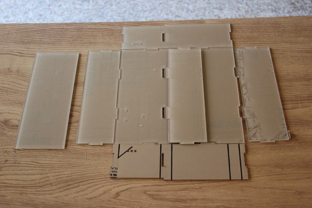
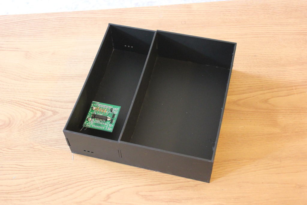
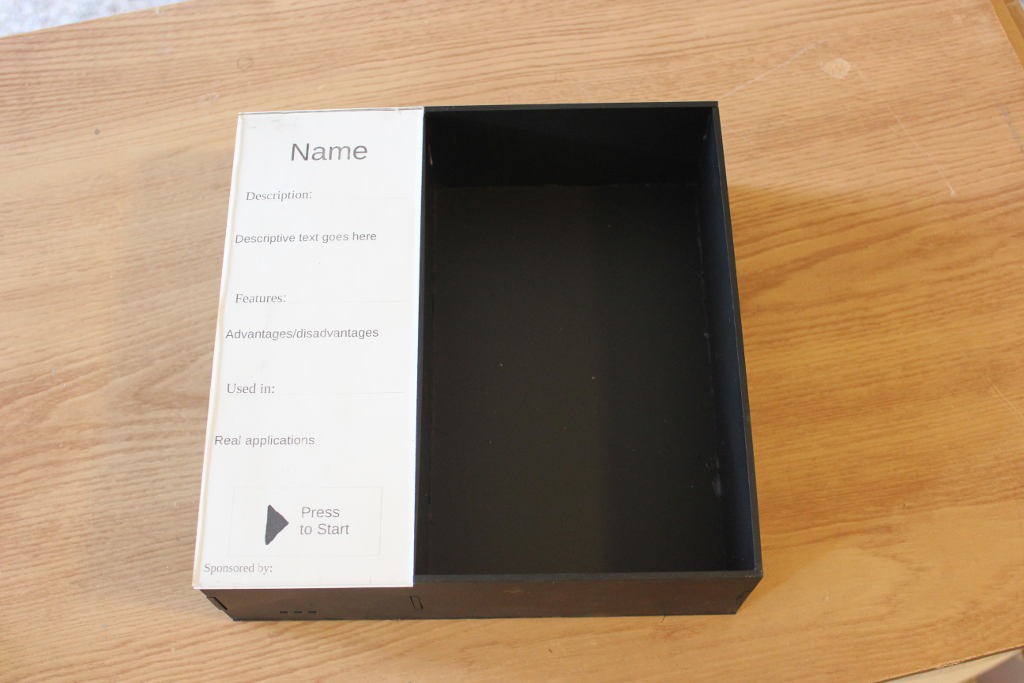
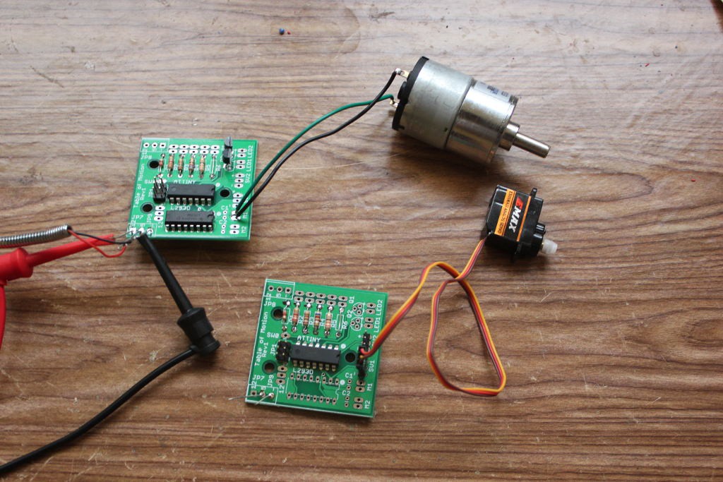
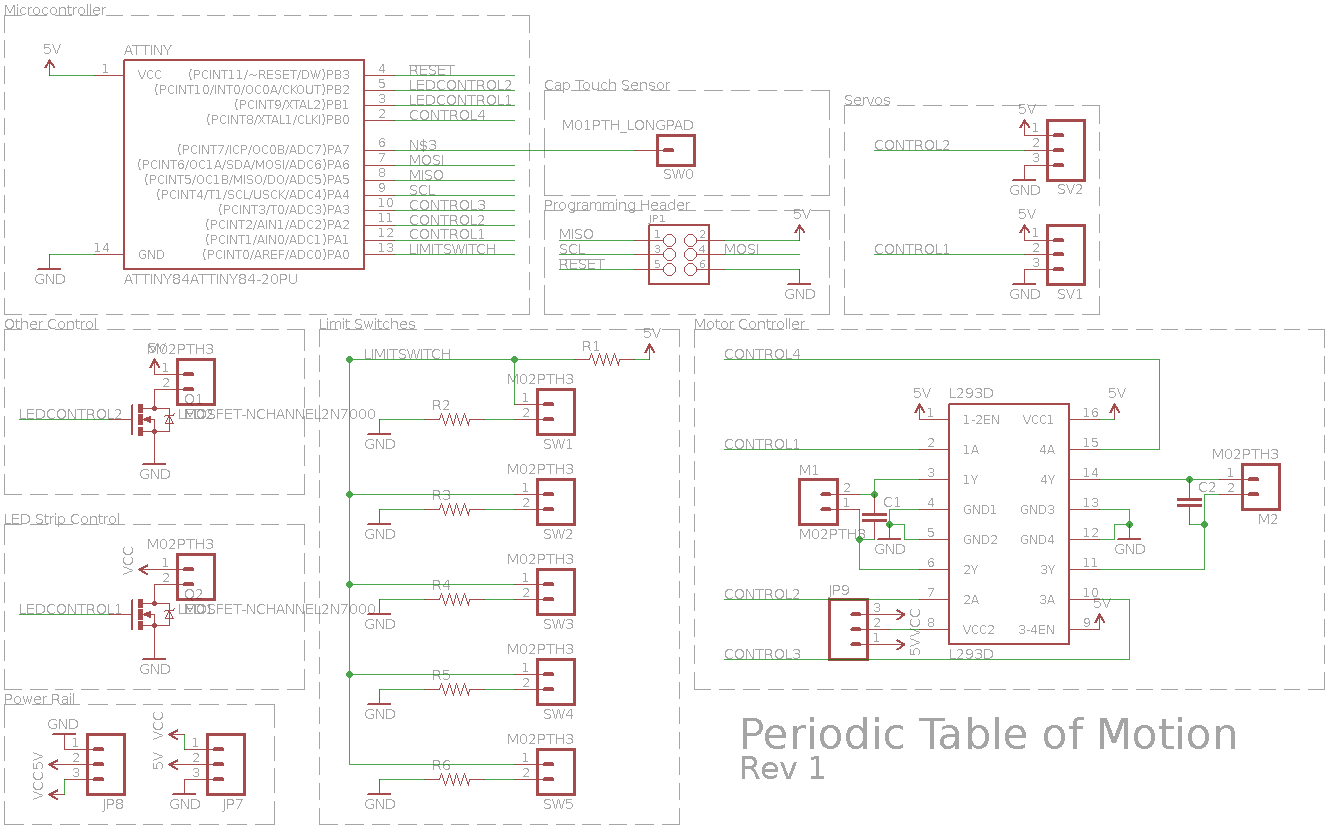
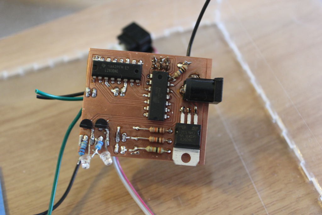
Cells are individual units that get power (+12V and +5V) via a bus. They are a standard size (9"x9"x3"). They have a standard electronics unit that provides for up to 2 DC motors, 2 Servos, 4 limit switches, and 1 switched output. All cells also have a single capacitive touch button to activate the cell, and a 12V switched output dedicated to an output for an LED strip to light up the activated cell (indicating that it has been activated). This project includes the template for everything, including the graphics, the design files for the enclosure and the main wall mount, the electronics, firmware units for Arduino, and a set of starter cells that make up a basic exhibit.
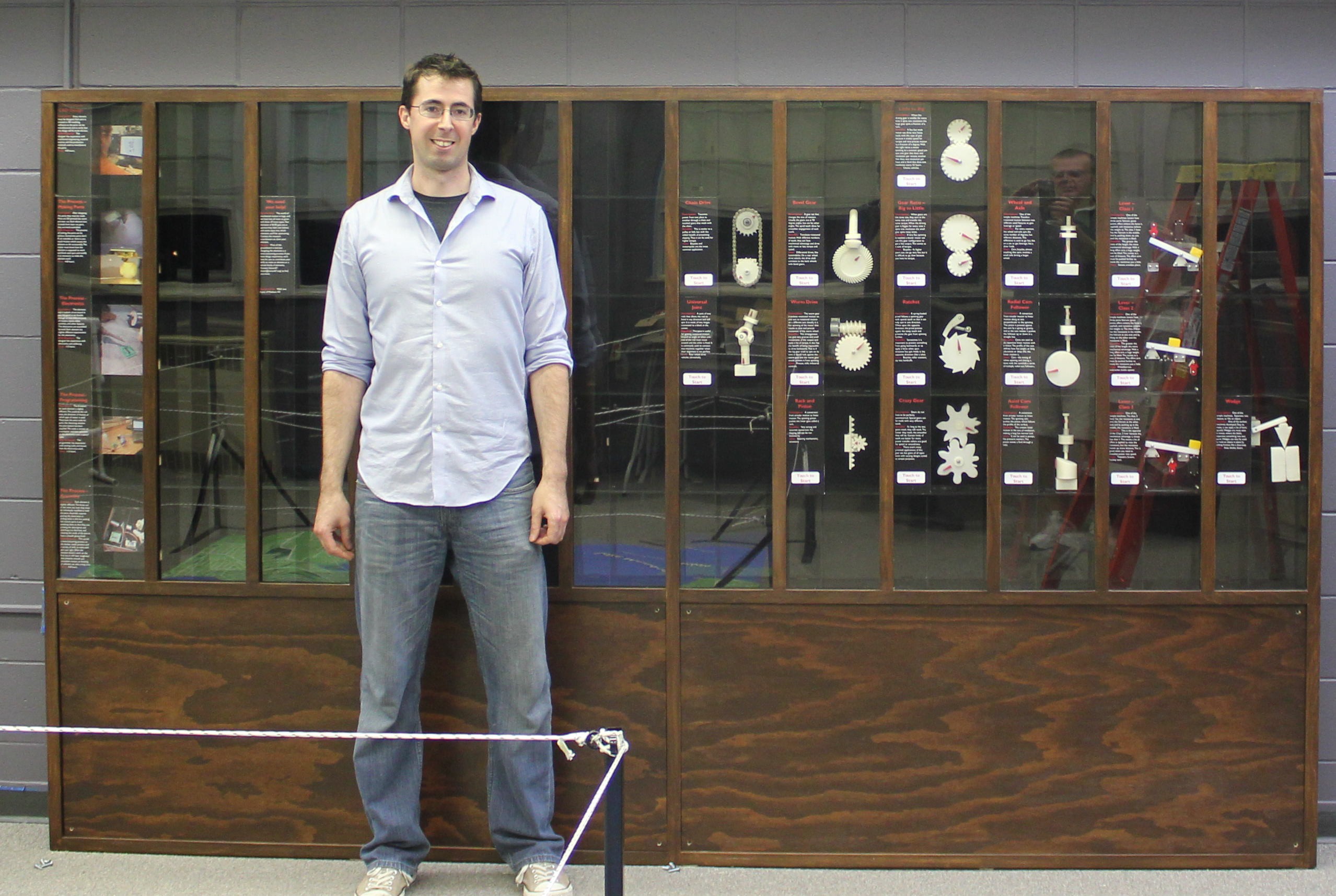
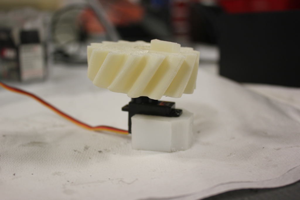
Anyone can create their own compatible cells using the templates, using the periodic table of motion framework to demonstrate all kinds of mechanical concepts.
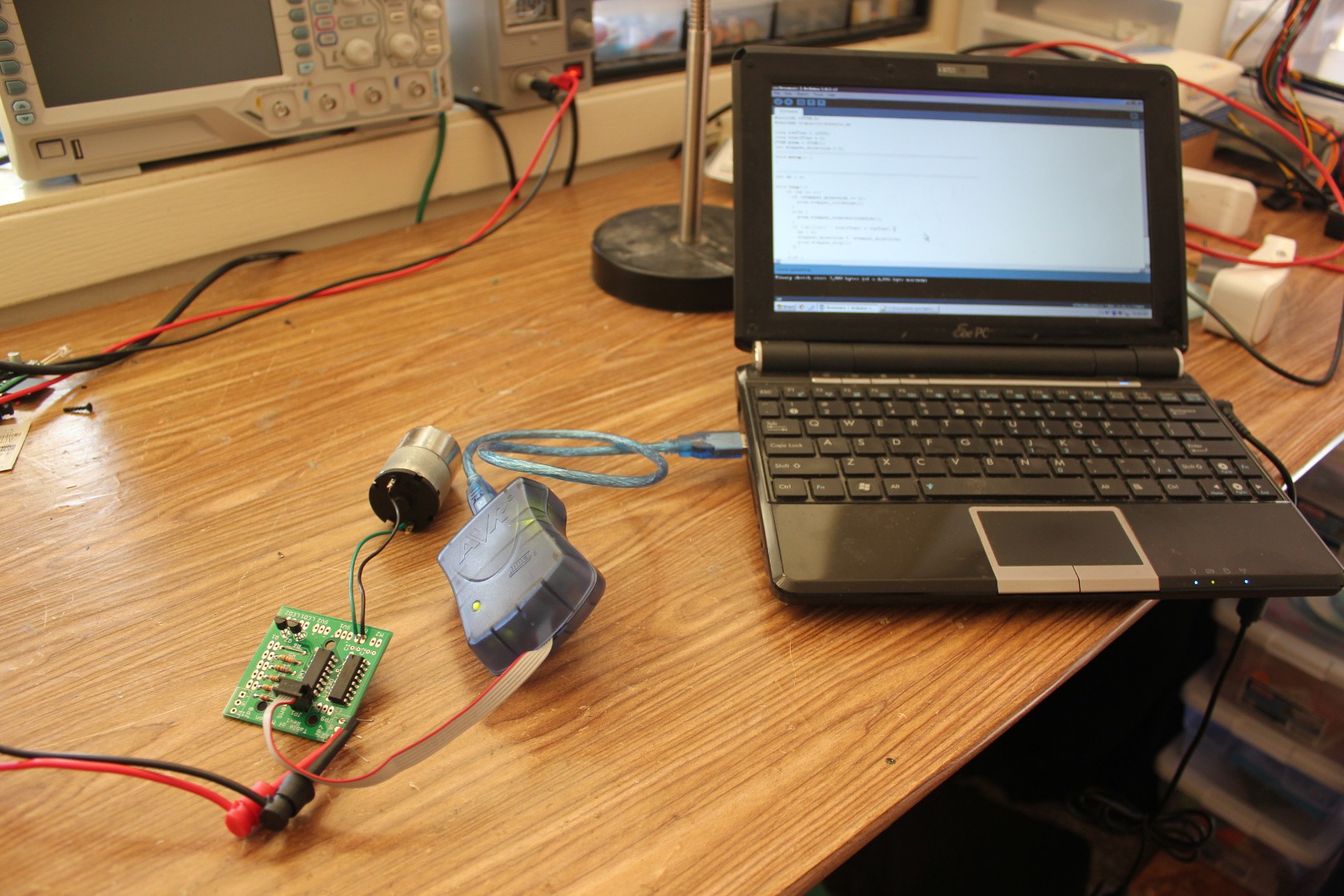
This project is completely open. The designs are free without any restrictions. I highly doubt it will be used for anything other than museums, and that's great! It uses the SoftwareServo and CapacitiveSensor Arduino libraries, but those don't seem to have license restrictions.

 Jarrett
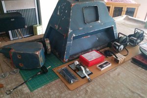
 Andrew Bills
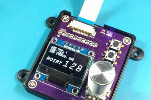
 CriptasticHacker
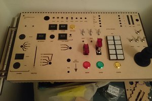
 Matthew Peverill
Very cool project I know how difficult it was for me to get just one mechanical mechanism working. Mine is up on my Hackaday.IO page.