Close
0%
0%

Remote Water Consumption Display

Design and build a simple, inexpensive, and manufacturable remote indicator for the most common type of mechanical water meter in use today.

Similar projects worth following
My project is to design and build a remote display for the most common type of mechanical water meters in use today. This system needs to be inexpensive, simple to install, and simple to use. In short, my Dad has to be able to use it. In its basic form, there will be a "sender" that is installed outside at the water meter, and a receiver placed inside the home. The receiver will display immediate water usage, along with historical consumption data. Further, the receiver will be able to connect with the consumer through the Internet to provide regular reports, as well as alert them to possible problems (pipe breaks, leaks, etc.).

PROJECT INTRODUCTORY VIDEO

Water is an issue now, and it will continue to be an issue in the future. Global warming, watershed reduction, waste, whatever the reasons, the availability of clean water is already a crisis in many parts of the country, and there is nothing to indicate the situation is going to improve any time soon. A major part of dealing with the water crisis is conservation, but that is not exactly easy.

Sure, "just use less water" is pretty easy, but we're humans. Unless you have your local water cop tapping you on the shoulder a few times a day you're going to forget. And if you're like the vast majority of Americans, you have absolutely no idea how much water you've used until your monthly utility bill comes. And that's a problem. You simply can not address a problem that you can not see, and you can not address the problem effectively if you do not have rapid feedback from changes and visibility of immediate measurements. That's what I want to solve.

There are a few similar projects out on the Internet, and while they are good, they have not been designed for simplicity, or for manufacturing.

While this project will likely result in a manufacturable product I have no intention of doing that myself. With all of my designs for this project being totally open and free, it is my hope that someone with the resources to bring it to market will use my work as either an inspiration or an actual foundation for a real product. If nothing else, maybe a lot of Makers can duplicate my project, and together we can save a little water. :-)

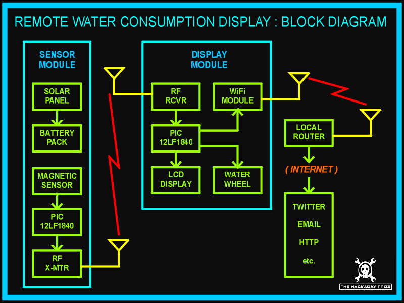
As it stands right now, I have nothing more than an idea and a rough block diagram. I will be chronicling the entire project here, from initial design, prototyping, design revisions, right on through to the final form. I hope you click on "follow" and come along for the ride.
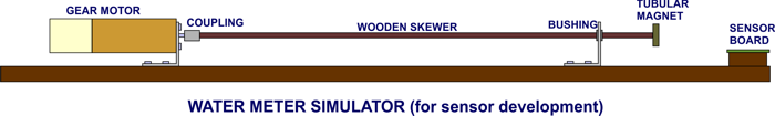
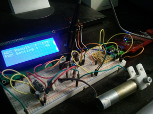
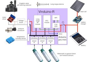
SYSTEM DESIGN:

I really think this is going to be fun. 8-)

John

Oh, by the way ... I'll probably be talking about this on Twitter and G+

       https://twitter.com/JohnS_AZ

       https://plus.google.com/u/0/102867471209152798204/posts

  • 1 × PIC12LF1840 Transmitter: Microcontroller
  • 1 × MAG-3110 Transmitter: 3-Axis Magnetometer Sensor
  • 1 × TWS-BS Transmitter: RF transmitter module, 4800 baud serial
  • 1 × MCP1702-3302 Transmitter: 3.3V LDO Voltage Regulator
  • 1 × 6V 900mAH rechargeable battery pack Transmitter: Power supply

View all 15 components

  • Log #14 Hostile Environments

    John Schuch01/20/2015 at 22:19 4 comments

    So, I've been working on my receiver code off and on as time permits. During this time my prototype sensor/transmitter was out at the water meter. I had placed it in zip-lock bag and tightly closed it with a rubber band. That was in another bag, and that whole assembly was held onto the water meter with a much larger rubber band (I think it came from a bunch of broccoli). All of the bag openings were down, and the large metal cover was placed over the meter box. Situated like that I had no worries about water getting to the sensor. Besides, I'd have PCBs soon and the final sensor would be fully potted.

    I can only guess, but here's how I imagine it happened.

    The city meter reader must have opened the meter box (who else would?) and noticed plastic bags wrapped around the meter.

    I'll avoid ascribing mental attributes to this unknown person, but for whatever reason, he (or she I guess) pulled everything off of the meter. That by itself would have been fine. But for whatever reason, this person removed the outer bag, then pulled off the rubber band and removed the inner bag. I presume he lost interest because he then tossed the bags, rubber bands, and the exposed sensor assembly (still attached to its power supply) several feet from the meter box. He replaced the metal cover, and left.

    Again, that would have all been okay but ...... that afternoon and night, it rained.

    *sigh*

    The pictures show the result of less than 24 hours exposed to the elements (under power). The strange thing is that pin number 5 that almost totally eaten through. That connector is the ICSP (programming) connection, and there was nothing plugged into it. All I can imagine is that it ended up with a VERY good connection to ground.

    At any rate, the PIC is cooked, and I have to replace the connector on the mag sensor, but I don't have high confidence that it works either. I haven't decided if I will recreate the prototype board, or just order and wait for custom board to come in (that I can actually waterproof).

    Oh well .... onward and upward.

    John

  • #13 Maybe you can buy one! (Just not from me)

    John Schuch11/21/2014 at 04:01 2 comments

    Interesting!

    I'm still working on firmware, and am waiting for another (faster) PIC for my sensor and will report all that when I have some accomplishments to talk about.

    Tonight, a good friend on IRC pointed me to a KickStarter project, the Water Hero, that is pretty much matches my project.

    Well, kind of.


    Let me say right up front, they have designed a very cool device!

    There are a number of differences between their design and mine and it really doesn't meet my requirements, but it may yours.

    - The Water Hero (WH) depends on WiFi from the sensor and talks directly to the internet. Mine talks to a base station.

    - The WH has no local dedicated display, a feature that I believe is crucial for awareness and conservation.

    - The WH is only suitable for indoors installation and virtually all water meters here are outside and underground. The KickStarter does say that an outdoors version is under development.

    - The WH requires an AC outlet to plug in the power supply. (My sensor is solar powered)

    - The WH requires you install an app to access the system, and they offer both a free and a paid 'premium' service to monitor your system. Again, no local dedicated display.

    - The WH has an optional shut-off valve actuator. (very nice!)

    - As far as I can tell, the WH is totally closed. Nothing "open" to it at all.

    It looks like they've done some fine work there, and I hope their project succeeds. If their product meets your needs, I would encourage you to support them.

    Several folks have asked if I am going to support their KickStarter.

    Well ..... no.

    I've already built one. :-)

    John

  • Log #12 Can you hear me now?

    John Schuch10/31/2014 at 16:12 0 comments

    Not a whole lot to report yet. I've been working integrating a real time clock (RTCC) to my project, and optimizing my code that drives the LCD display. But one interesting thing did happen ... I got interviewed.

    Elecia White, one of the Hackaday Prize judges, and her husband Christopher White host and produce a podcast called "Embedded". I am a bit of a podcast junkie, and theirs is one of my favorites. I was a bit startled when Elecia contacted me and asked if I'd like to be a guest on their show. I mean, they have some pretty notable guests on there and I had a bit of an "I'm not worthy" moment. But one of the up-sides of being my age is that you can approach a lot of things saying "What the hell, sounds like fun." So last Saturday we recorded the show and now it has been published.

    In it, we discuss the hackaday prize contest and my entry, or course. We also talked about contests in general and a raft of other topics. All in all it was a great deal of fun talking with them and the 70 minutes flew by amazingly fast (and I don't think I came across as too big a doofus).

    So THANKS Elecia and Chris for having me! And I hope you folks enjoy listening to it.

    Here's the link: EMBEDDED #74 : ALL OF US CAME IN SIXTH

  • Spacesuit Order Cancelled

    John Schuch10/13/2014 at 20:10 1 comment

    Well, the top five entries in the Hackaday Prize have been announced, and I didn't make the cut.

    Am I angry? Nah. Am I bummed? Yeah, you could say I'm moderately bummed. But that is kind of offset by the fact that the projects that did make the final five are pretty awesome. I can't point to any one of them and honestly say that my project is superior (though I think I match a couple of them). What's more, I'm probably going to use the SatNOGS project as source material for my own ALT-AZ antenna mount design, and the PortableSDR? Damn, I just want one!

    And this being bummed out about not making the elite five will be so short lived that it's almost passed as I write this. Here's the thing. I believe you can choose your attitude and your outlook. You don't have to let disappointment and the little dark voices color your thinking. So I CHOOSE to look at it this way; I came in 6th. As far as I'm concerned all 45 of us that didn't make it came in 6th. And you know what? 6th out of 800 is PRETTY DAMN GOOD! :-)

    As for the project, I am absolutely going to finish it and complete the documentation here. It's kind of funny that not making the final five will actually improve the quality of my project. Had I made it, it would have been a crazy push to meet the final deadline. Now, with deadlines off the table, I can take a little more time. I want to improve the code in my sensor module, and the code in my display will certainly be much better for not having been written in a time-crunch. That being said, I am going to take a break.

    Maybe a week or two. The weather is finally cooling off here in the desert and I can start using my real shop again (I've been working on a small table in my living room). It's also a train wreck out there, so I'm going to spend a week or two getting my shop bailed out and cleaned, and spend some time just not thinking about this project or the contest. I'll come back to it refreshed, because this HAS been quite a push.

    So ...

    Congratulations to the final five! You're doing some amazing work!

    Congratulations to all the other 6th place winners!!

    Thank you to everyone who followed my project, gave it skulls, or left comments.

    Thank you to Hackaday and SupplyFrame for running such an awesome contest.

    And Thank you to the judges who took on such a daunting task (even though you chose poorly) . <grin>

    I'll see you all back here in a week or so. :-)

    John

  • Preliminary Receiver / Display Schematic

    John Schuch10/08/2014 at 23:22 0 comments

    I kind of wish I had this done before the judging, but, here's the preliminary schematic for the receiver/display portion of my project.

    Click HERE for a more readable version of the schematic.

  • First real-world problem detected!

    John Schuch09/30/2014 at 22:22 0 comments

    So, it was 2:30 pm and I was working at my desk, and on the bench to my left my water meter project was sitting there turned on. I've been doing multi-day testing on it. Then all of a sudden I notice that the water wheel display is spinning. I was the only one home and no water was running (toilet flushes in remote parts of the house have startled me a couple times). With no water flowing in the house my first thought was "Oh crap! Something's gone wrong with my project !" 

    The first thing to check was the sensor so I went out to the street and took the cover off of the water meter box. Sure enough, the sensor LED was flashing away. Then I noticed ..... there actually was water flowing! The city water meter was clicking away. It took a few minutes to figure out ...

    We live on a full acre lot, and WAY WAY out back we have a little vegetable garden. The garden has it's own little irrigation system and it's own timer. The timer is set to water everything first thing in the morning because watering in the afternoon or evening leaves everything damp over night and promotes rot and disease (or so a bunch of websites and books say). It seems that the storms we had this past Saturday that took out our phones and internet also scrambled the irrigation timer. I reprogrammed the timer, came back into the house, and the water wheel had indeed stopped.

    Now, watering the garden at the wrong times isn't really a crisis level problem (though Lisa who's in charge of the tomatoes back there might disagree). But it is a problem. A failure. The thing is this project isn't even completed and it's detected its first real water related problem!

    I'm just sitting here grinning.   :-)

  • Log Entry #8 : Sensor/Transmitter Complete !

    John Schuch09/28/2014 at 14:36 0 comments

    After quite a bit of development and experimentation, the sensor/transmitter portion of this project is complete. I'm VERY happy to report it has successfully transmitted water consumption data from the meter to my desk. 

    As you can see in the schematic below, the circuit is not really all that complicated. There are two areas of trickiness. The transmitter / receiver pair that I bought for this project, and the software.

    The transmitter and receiver are intended to be use as a wireless serial port link. I had initially thought that would be fine, just sending one character for every water meter tick. After trying that for quite a while what I discovered was that the software overhead to move ASCII characters to the transmitter seriously slowed down the processor in the sensor module. Since I wanted the highest resolution (sample rate) possible from the sensor, that wasn't going to work.

    I then found the original manufacturers data sheet for the receiver. While it really has painfully little technical information, I did notice that one of the pins on the receiver was labeled as an analog out (without giving ANY details what the signal actually was!). Well, after playing around with it and my oscilloscope, what I discovered is that the analog output is either some sort of carrier detect signal, or a signal strength indicating signal. Being on deadline for the contest I didn't dig into it very deeply (but I will later). The important point; I found that if I simply sent a pulse to the data input of the transmitter, I'd see a pulse on the analog output of the receiver! Granted, a strange pulse. The analog out floats around 3 volts, and the pulse lifts the signal to about 4.5 volts. While that's a pretty crappy thing to feed into a PIC microcontroller as an interrupt signal, I found that if I capacitively coupled the analog signal to the PIC the spike that got passed was easily sufficient to reliably trigger the interrupt. 

    Using the transmitter/receiver pair in this way vastly reduced the amount of time it took to send a meter tick to the receiver, and greatly increased the sample rate of the sensor.

    The other tricky thing is my auto-calibration routine in the sensor microcontroller. 

    NOTE: The source code for the Sensor/Transmitter can be found HERE.

    The sensor is a three-axis magnetometer, and obviously measures magnet fields in three axes at the same time. What I thought was that if I could have the PIC figure out which of the axes was getting the best (widest span) measurement it could then focus on that axis and ignore the others. This is significant because it means that an end user doesn't have to worry about how their sensor is oriented relative to the water meter. 

    At power up the microcontroller goes into an auto-calibration mode. I continuously monitors all three axes recording the highest and lowest value for each. It continues doing this until it detects that it has measured at least 5 full revolutions of the water meter. Then, it calculates the span of each axis, determines which had the greatest span, and then only monitors that one axis for normal operation of the sensor. 

    NOTE:  Water must be flowing through the meter for auto-calibration to complete. 

    To test this, I reset the sensor many times with it in various orientations relative to the water meter. As expected, different orientations resulted in different axes being selected as the primary measurement axis. Nice. :-)

    One other thing dawned on me that would would be a problem. My water meter is installed underground. I was planning on installing the transmitter on the same PCB as the sensor and microcontroller. Well, a low-powered RF transmitter isn't going to function very well buried 12" under ground, and under a heavy steel cover plate. Luckily I figured this out before actually assembling the prototype.

    I was already planning on having an external box that would contain the battery pack and run power leads down to the sensor....

    Read more »

  • Log Entry #7 : Sensor processor complete (mostly)

    John Schuch09/21/2014 at 06:33 0 comments

    As you'll see in the video below, I have most of the firmware for the sensor/transmitter module complete. All I have left to do is remove the code used to drive the LCD display (which is only used for code development and debugging), and redirect the serial output to the transmitter module. Then a couple hours to move the components from a breadboard to the PCB proto area of the microcontroller development board. With those done, the sensor/transmitter module will be complete.

    With the transmitter complete, I can turn my attention to the receiver and display system. I have most of the hardware put together and working, now I'll be able to receive the sensor pulses via the radio link and actually work with real data. 

    I can now see light at the end of the tunnel. :-)

  • Log Entry #6 : Harbor Freight for electronic components????

    John Schuch09/05/2014 at 21:04 0 comments

    My prize entry needs a solar charged battery back to power the sensor and transmitter I'm placing in front of my house. Rather than spending a whole lot of time finding domestic suppliers of small photovoltaic panels and trying to spec a nicad or nimh battery pack, I decided to buy a "60 LED Solar Security Light" from Harbor Freight just a few miles from here. The list price was $32.99US, but it was on sale, plus I had a 20% off coupon so it ended up costing me about $20.00US. I doubt that once you consider shipping, I could have bought a solar panel and battery back for less than that. What's more, I ended up with a big LED panel and a motion detector module for use in future projects.

    Here is the video of my tear-down and analysis of the light:

    The photovoltaic panel and battery pack are going to work great for my project. I think I will duplicate the single-diode "charging circuit": It just can't get simpler than that. Next up, code for the transmitter.

  • Log Entry #5 : A water meter simulator????

    John Schuch09/02/2014 at 02:44 0 comments

    So, I started working on the code for the sensor/transmitter.

    I'd edit code on my bench, flash the chip, haul it all outside to the meter, test it, haul it all back inside, and repeat.

    Now, this is Arizona, and it's about 110F out there. I did about 3 cycles of that before I decided something had to change. 

    I dug around in my shop and came up with a nice little DC gear motor. I attached a magnet to the shaft and tried it out. I pretty quickly figured out that the windings and magnets in the motor were creating a larger field than the magnet on the shaft. Then I got a piece of dowel and extended the magnet away from the motor. This worked well, I could read the magnet without getting magnetic interference from the motor itself. Then another problem cropped up. I was using a variable bench power supply to run the motor. It worked fine, but when I tried to slow the motor down (water meters can run VERY slowly) by reducing the voltage, the motor would just stall. The slowest I could get the motor to reliably spin was about 20 RPM, not nearly slow enough. It seemed pretty clear to me that what I needed was as actual motor controller, and down another rabbit hole I went.

    I decided that I needed a PWM motor controller. Since in a PWM system the motor always sees full voltage (just varying duty cycle) it should run a much lower speeds without stalling. Torque from the motor will also fall dramatically, but in this application there is virtually no load on the motor anyway. 

    I decided to use a Microchip PIC12F1840 microcontroller for my motor driver. I selected this chip because 1) it has an analog to digital converter built in, 2) It also has a PWM generator on chip, and 3) I had a bunch of them laying around. It only took me a few hours to draw up a schematic, find all the parts in my shop, and put the thing together on a breadboard. You can see the schematic HERE.

    After another few hours, I had basic software running to do the analog conversion of the voltage level from the speed setting pot, and basic functionality of the PWM generator contained in the PIC. In the above picture you'll notice an LCD display. That display is not part of the final circuitry. I have a few LCD displays with serial backpacks installed and find them invaluable for writing code for microcontrollers. They only take up one pin (TX), and you can send all sorts of debug or status messages to them while you're writing/debugging your code. Once the code is done you can pull out the LCD display and delete the display code from your source. 

    I was going along fine until I hit a roadblock in the code that had me banging my head on my desk for a couple hours. Luckily Jayson Tautic, a friend from IRC, found the bug. Let's just say that MAYBE I should give up doing binary conversions in my head from now on. Changed a "512" to "256", and it ran perfectly. Thanks Jayson!!

    Once I had the code running well, I transferred the circuitry to a little PIC-specific dev board. I tested that construction with the new code and it worked very well. From there, I found an old slat of redwood and mounted the board, motor, pot, magnet, and the sensor. The final result worked perfectly. Using this system I was able to get the motor turning reliably at about 5 RPM. Slower would be better, but that's plenty slow enough to test my sensor, and develop code for the transmitter. 

    Since this little motor controller project isn't really part of my contest entry, it didn't seem right to fully document it here. I did, however, write up a complete blog post on my website that details the circuitry, and provides all of the source code for the PIC (Public Domain). You can find that page here:

    http://hackersbench.com/Projects/PWM/index.html

    So that's how I spent Labor Day weekend.

    I have two goals for this week:

    First, I want to get that solar flood light I bought from Harbor Freight torn apart (the true "hack" part of this project) and start looking into scavenging it's panel, batteries,...

    Read more »

View all 14 project logs

  • 1
    Step 1

    Build Instructions.

    Huh.

    I'm honestly not sure what to put in this section, but the rules say I need build instructions.

    I mean, I am posting all of the schematics in the Build Log entries, All of the source code is up there. When I get to the point I have PCBs the artwork will be posted, and everything about this project is open source.

    So, I guess the Build Instructions are as follows:

    1) Buy all the parts as I've listed them above.

    2) Wire them together as per the schematics I've posted above.

    3) program the microcontrollers from the source code I've linked up there.

    That's about it. I'm really not trying to be flip or insulting. As I go along if some aspect of this project needs a more in depth explanation, I'll certainly add it.

    And in the mean time, if YOU think of anything I should include in this section PLEASE do not hesitate to leave a comment for me!

View all instructions

Enjoy this project?

Share

Discussions

Pedro Perez wrote 06/29/2018 at 20:34 point

hello friends this publication is very interesting if you like this type of blogs could also be interested http://www.logicbus.com/ is very interesting as this can also learn.

  Are you sure? yes | no

hack wrote 09/29/2014 at 03:20 point
Are you having any problems measuring peak and fall on the sensor at higher RPMs? I imagine that the mains meter will have the potential to spin rather fast.

  Are you sure? yes | no

John Schuch wrote 09/29/2014 at 05:01 point
I wondered about that but haven't seen any problems. I turned on a garden hose on full and turned on a sprinkler circuit and the sensor seemed to keep up. If I do see a problem I have the option of dialing back the oversampling in the sensor which will boost the sample rate from 20Hz to 40 or 80.

  Are you sure? yes | no

Eric Tsai wrote 09/15/2014 at 05:55 point
Hi,
I'm doing a home automation project myself. Your idea of using the magnetometer is great. I didn't know the wheel thing has a rotating magnetic field. I'm excited to give this a try.

My home automation project has many of the elements yours does - wireless transmitter, a server platform. I'd like to do some alarming for long periods of water usage, which might indicate that someone forgot to shut off something.

Just wanted to express my appreciation for the idea.

  Are you sure? yes | no

John Schuch wrote 09/15/2014 at 22:41 point
Thanks, and good luck with your project!
I'd be interested in hearing how it goes.
John

  Are you sure? yes | no

Jac Goudsmit wrote 08/25/2014 at 20:10 point
Congratulations on making it to the last 50 of the Hackaday prize! http://hackaday.com/2014/08/25/50-semifinalists-selected-for-next-stage-of-the-hackaday-prize/

  Are you sure? yes | no

joram wrote 08/09/2014 at 23:40 point
Also consider metric units, for those non US residents. You might also add a second sensor on the hot water flow for example, to measure the consumption of heated water, with temp sensor. As a matter of fact, a tempel sensor on the cold input alsof makes sekse. We alsof Reuss rain water, zo mocht as welk measure that amount. Thuis gives an overview off all the water consumption of a household. As input we could measure the inflow on the rainwater tank. Just if you run out of ideas...

  Are you sure? yes | no

Jelli wrote 07/18/2014 at 19:15 point
You will find the hardware you are looking for at Sensus.com, BadgerMeter.com and tehamawireless.com. There are several major companies releasing consumer products very soon.

  Are you sure? yes | no

Rogan Dawes wrote 07/18/2014 at 05:53 point
I'm fascinated with the idea of measuring water flow, and doing real-time reporting, not so much for individuals (although that's certainly important!) but also at a utility level.

For example, i f you have a main pipe that is recording 100l/s flow, and 3 subsidiary pipes that are reporting 10l/s flow, you either have exceptional demand from the consumers between the main pipe and the subsidiary pipes, or you have a burst pipe somewhere. Being able to detect that and react in real time without waiting for a resident to report it would be incredibly useful.

One problem I have is powering the sensor and transmitter, of course, but I was wondering how difficult it would be to "siphon" off a little energy from the flow of water itself. Obviously I don't want to put anything into the pipe that would obstruct the flow, or be at risk of damage when the inevitable grit and small stones get into the pipes during maintenance. I have just discovered that water is diamagnetic, and wonder if there is a way of using that property in conjunction with a powerful magnet to generate enough energy from the flowing water to power the sensor and the transmitter.

  Are you sure? yes | no

CasualCasual wrote 07/17/2014 at 15:04 point
Have you done power consumption tests for the magnetometer and wireless transmitter? I imagine the wireless transmitter will be the big power hog. I've seen power specs for that Mag at about 24uA, along with 10uA for the PIC, with .55ah per 9 volt is about 2 years of run time, but the transmitter needs about 8mA, which if running constantly would only give you about 3 days of run time.

This is a really interesting project, and I'd be interested to see exactly how much water I'm using during my overnight lawn watering.

  Are you sure? yes | no

DeepSOIC wrote 06/28/2014 at 20:13 point
And how about optical readout? I've seen people make covers (or shields) over standard water meters which have a led-phototransistor pair sensing the rotation of a black cogwheel. Does your meter have such a cogwheel (a black asterisk-like thing that spins)? Looks like these cogwheels are added deliberately for the purpose.

  Are you sure? yes | no

DigiGram wrote 06/20/2014 at 17:17 point
I really like this idea. Our water measurements are not taken monthly for the bill, they just estimate (recently bought a house and the meter was not read in over 2 years!) So we have to read the meter monthly and email the reading in. Something like this can be scripted to automatically send the readings monthly (and my wife has asked me for something like this just last month). I'll be following your progress.

P.S. I like your way of going about it without changing the plumbing etc!

  Are you sure? yes | no

John Schuch wrote 06/20/2014 at 17:28 point
Thanks for the comment! My motivation .. a few years ago we had an underground irrigation pipe break and I had no clue until we received a multi-thousand dollar water bill. (I settled the bill for much less) But still, I want to be able to keep an eye on it.

  Are you sure? yes | no

Adam Fabio wrote 06/14/2014 at 02:03 point
Great Idea! Many people take it for granted, but water is a precious resource. I can't wait to see how you implement your meter side sender. Don't forget to document your design as you go along, and thanks for submitting to The Hackaday Prize!

  Are you sure? yes | no

John Schuch wrote 06/14/2014 at 01:53 point
Hi Jac. (Don't know why this thing won't let me reply directly to your comment) I think there are a few issues with using a RPi and camera in this application. First is obviously cost. Then there's complexity. I envision a system where you place a sensor near the meter and you're done. With a RPi and camera you have to mount and aim the camera, and teach the vision system what to look for on the water meter: Fails the "my Dad can do it" test. :-) And power. A PV panel and battery pack for a sensor and simple transmitter will be fairly modest, while powering a RPi and camera would take a LOT more juice. And finally there's the nincompoop city meter reader. If he bumps that camera, you'd get to start all over again. I don't think it would be "cheating", and it would be a cool project. It just doesn't mesh with what I'm after.

  Are you sure? yes | no

John Schuch wrote 06/13/2014 at 15:41 point
Yes, that would be ideal, but adding a new flow sensor would vastly increase the cost. I've decided that a design requirement is that the system can not require modifications to the existing plumbing. Essentially, I want to read the meter that is already there. The mechanical meters I'm talking about have an internal magnetic coupling, and I plan to detect that externally.

  Are you sure? yes | no

zakqwy wrote 06/13/2014 at 16:10 point
Makes sense. Great start!

  Are you sure? yes | no

Jac Goudsmit wrote 06/13/2014 at 19:19 point
Have you thought of just putting a Raspi with a camera on the meter, and running some software to either transfer pictures over Wifi, or (a bit more difficult) read the numbers straight off the camera picture and process the data in cool ways e.g. build statistics files, show the difference between now and yesterday etc.)? That way you don't need sensors to sniff out the magnetic coupling. Of course, on the other hand, you could argue that that method would be cheating, and probably also less fun ;-)

  Are you sure? yes | no

zakqwy wrote 06/13/2014 at 15:36 point
Have you thought about an electromagnetic flow measurement system? Better reliability and accuracy vs mechanical meters, but a bit tougher to design and build.

  Are you sure? yes | no

CasualCasual wrote 07/17/2014 at 14:41 point
You'd have to put that in-line with the main supply valve, and water companies get skittish when they see that you've mucked about with their system. (to the tune of replacing the meter and sending you the bill for it)

  Are you sure? yes | no

zakqwy wrote 07/17/2014 at 14:45 point
What about a homemade clamp-on meter? Think that's in the realm of possibility for a DIYer? Seems like the transducers would be tough to build..

  Are you sure? yes | no

CasualCasual wrote 07/17/2014 at 15:57 point
Hmm, I hadn't ever heard of indirect flow meters. There's an ultrasonic version that requires bubbles or particulate matter in the water to sense flow. http://www.omega.com/prodinfo/ultrasonicflowmeters.html This one in particular says that it won't work with clean drinking water.

Maybe this paper could prove useful? http://www.sersc.org/journals/IJCA/vol5_no4/18.pdf I don't have time to read it right now though.

  Are you sure? yes | no

zakqwy wrote 07/17/2014 at 16:12 point
Ultrasonic meters generally work on one of two principles; the unit you describe uses the Doppler effect, bouncing a signal off of entrained particles or bubbles. Other units, called 'transit time' meters, use a pair of spaced transducers to compare the relative sonic velocity of the fluid with and against the flow direction, and use the time differential to calculate fluid velocity (since sound is just a pressure wave moving through a medium).

Acoustic coupling and ignoring incorrect pulses are two of the many challenges to building one of these setups yourself, but it would be a fun project!

  Are you sure? yes | no

CasualCasual wrote 07/18/2014 at 13:05 point
Somehow your description made it sound much more complicated than this video I found. https://www.youtube.com/watch?v=rqJ9snaqYiY
Here's another informative video, https://www.youtube.com/watch?v=b1V4fzpDvAM

Seems like it'd be worth trying though. It might be tough to mount in this particular application since you'd have to have a good section of pipe, but it'd be a neat test that others might find useful. Most of the indirect flow meters I've seen in my tiny bit of research have been very expensive, so an open source version might be pretty nifty.

  Are you sure? yes | no

CasualCasual wrote 07/21/2014 at 17:12 point
So, with some angled wedges and some ultrasonic emitter/sensors an indirect flow meter could be made. Repurposing a range finder might work, especially if the price can be found low enough, http://www.epictinker.com/Ultrasonic-Distance-Sensor-p/hc-sr04.htm . Maybe unsolder either the transmit or receive transducer, add a cable extension that way you can get the distance between the transducers correct. 3d print a housing with some hose clamps to attach it to a pipe.

I'm not sure what the wedges would need to be made of. The specs I've seen say "sound conductive material" which makes me think a hard silicone or a large block of pencil eraser, but I'm not too sure. Maybe even hot glue pumped into place within the housing attached to the pipe so there wouldn't be any air gap to cross.

With more free time it'd be a fun little project to try. Not sure how great the battery life would be for a remote sensing application. This type of sensor would need to be running continuously to keep up with flow.

  Are you sure? yes | no

CasualCasual wrote 07/23/2014 at 15:49 point
Something like this maybe, http://i.imgur.com/ghYIrvU.png

  Are you sure? yes | no

Similar Projects

Does this project spark your interest?

Become a member to follow this project and never miss any updates