Like this...
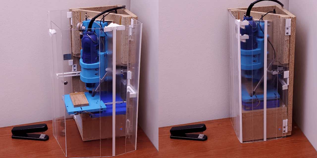
...as of April 2024
Check out...
this photo gallery of work examples.
Companion projects...
#Minamil 3dp: another minimal CNC mill and #Minamil 2dc: a minimal CNC mill develop the CNC mechanics. Neither of those projects require this project. This project focuses on fancy packaging, integration, and compactness that I like for my use case.
Sparse here; more in the Log entries
This page used to have more "details", but they had become unhelpfully stale details, so I squashed it down to this until I get around to writing up a freshtastic new Details page.
 Paul McClay
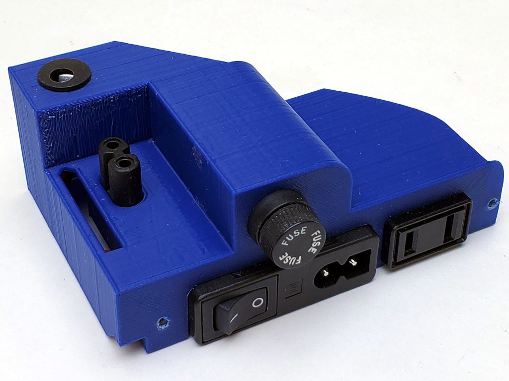
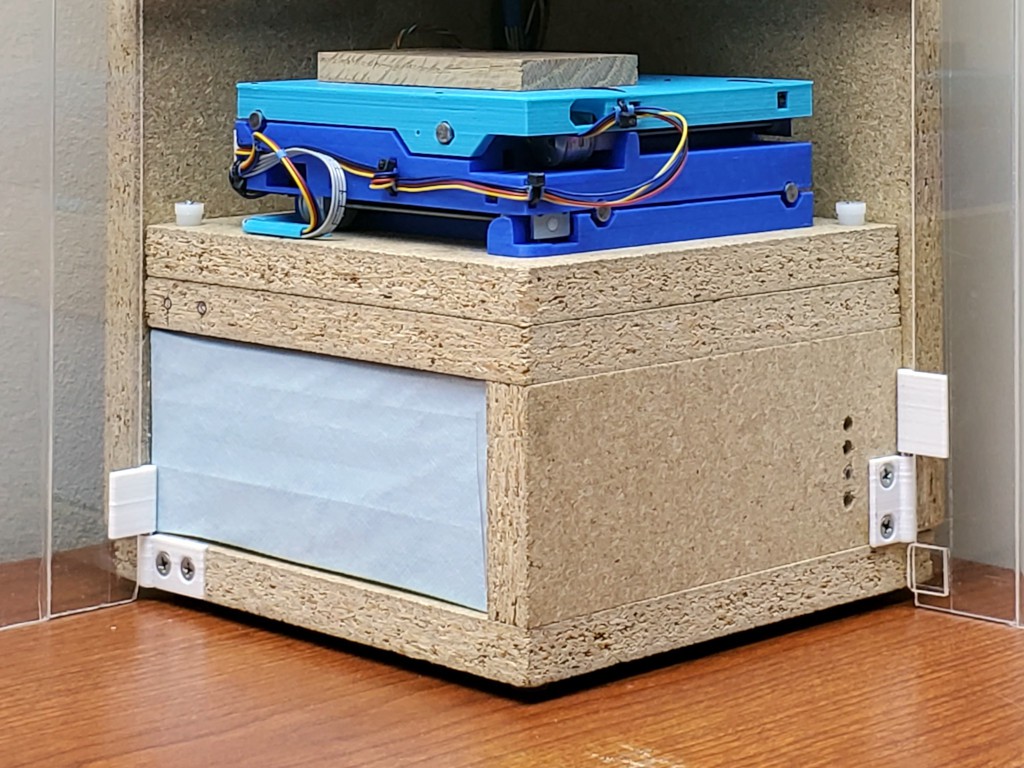
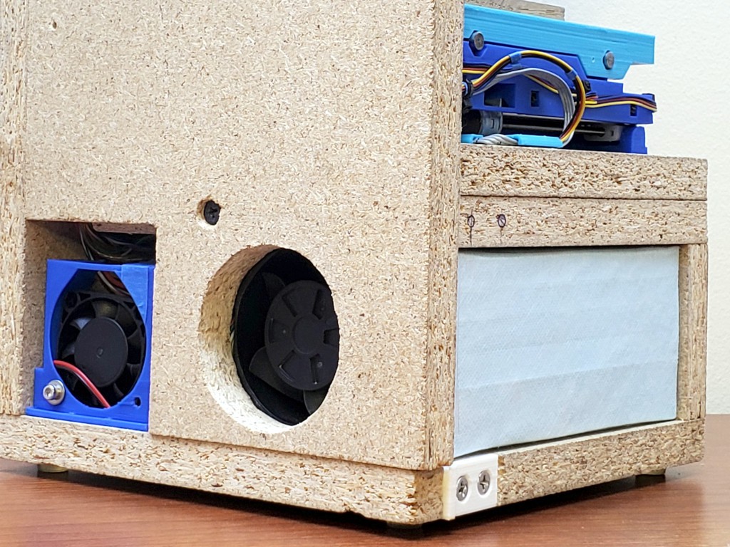
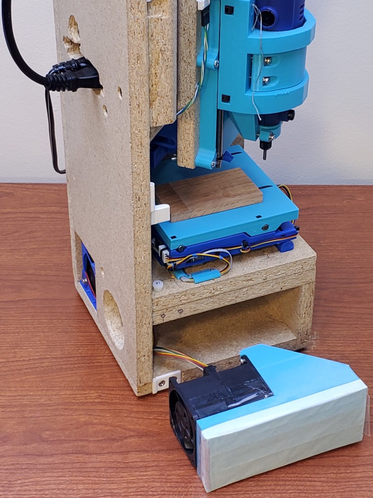
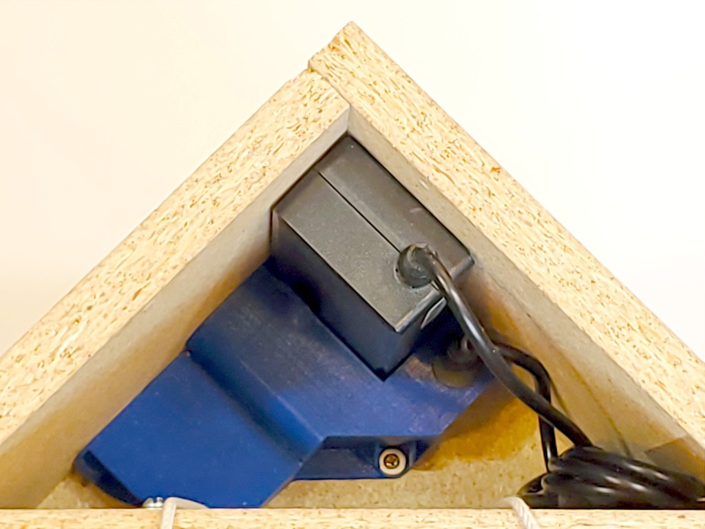 The DC-out cord from the supply could be cut down to the minimum needed to make the connection.
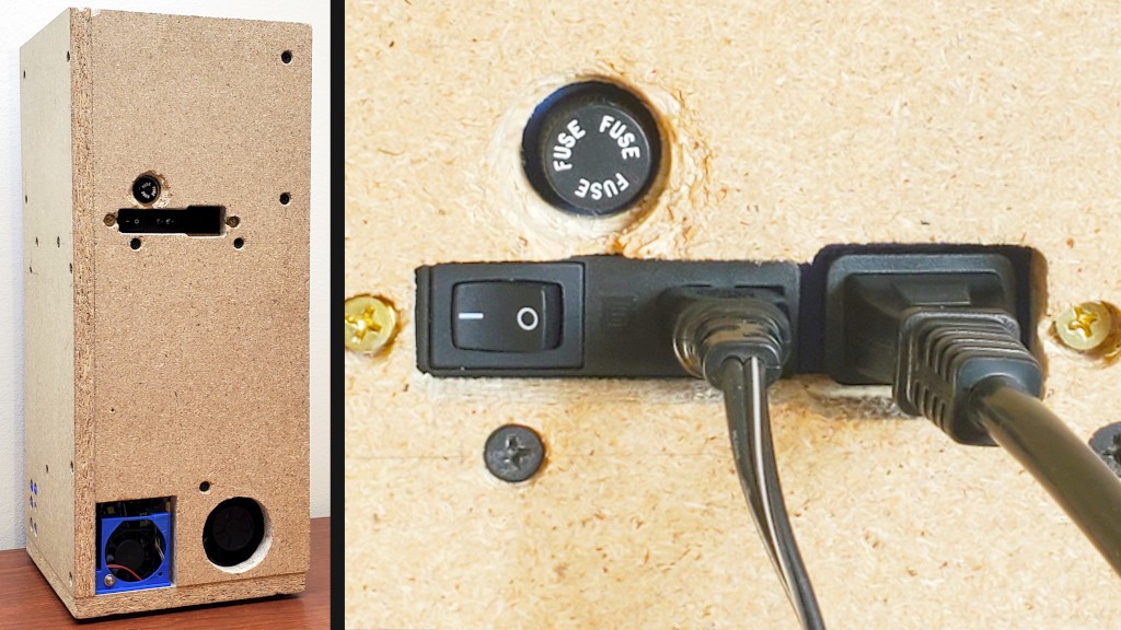
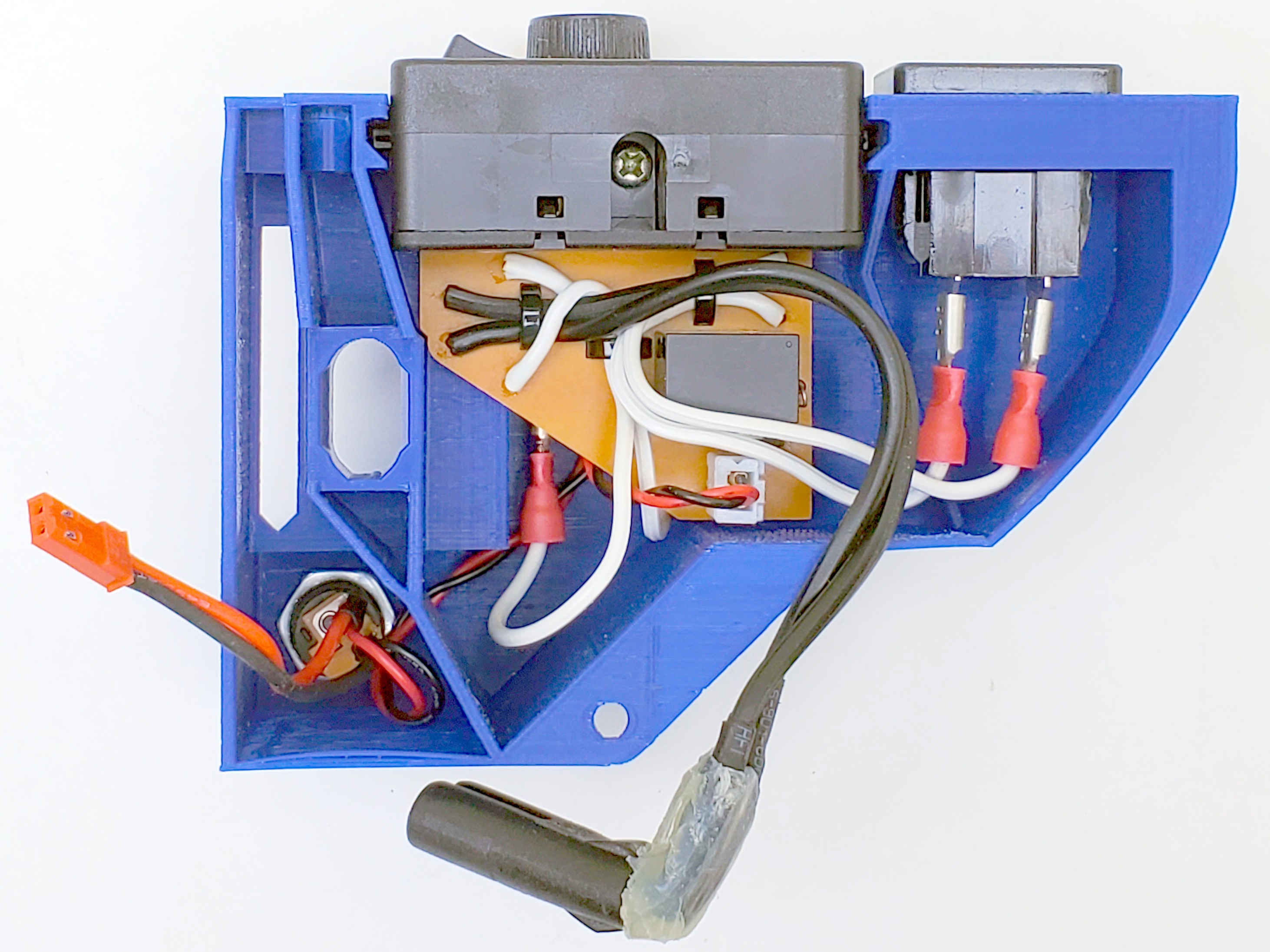
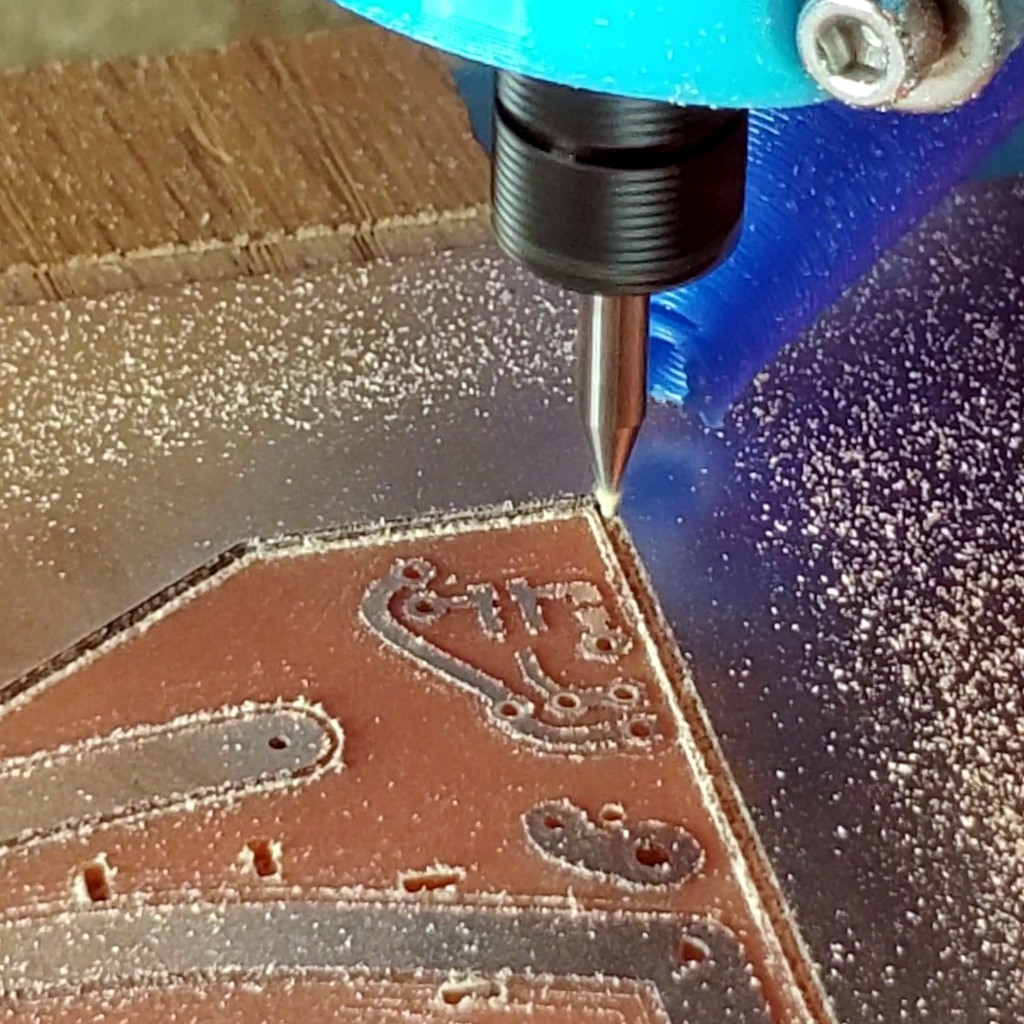
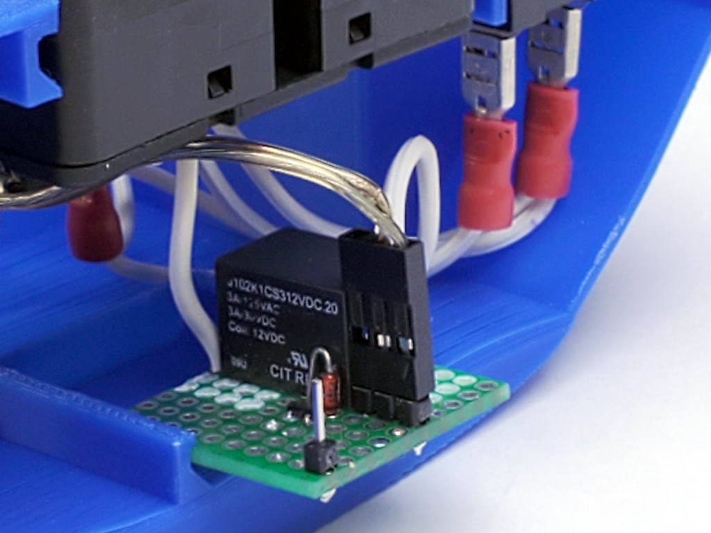
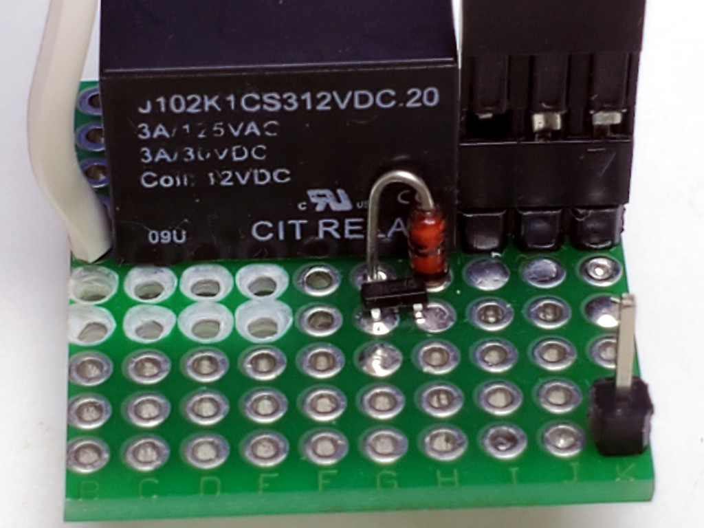
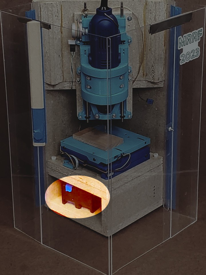
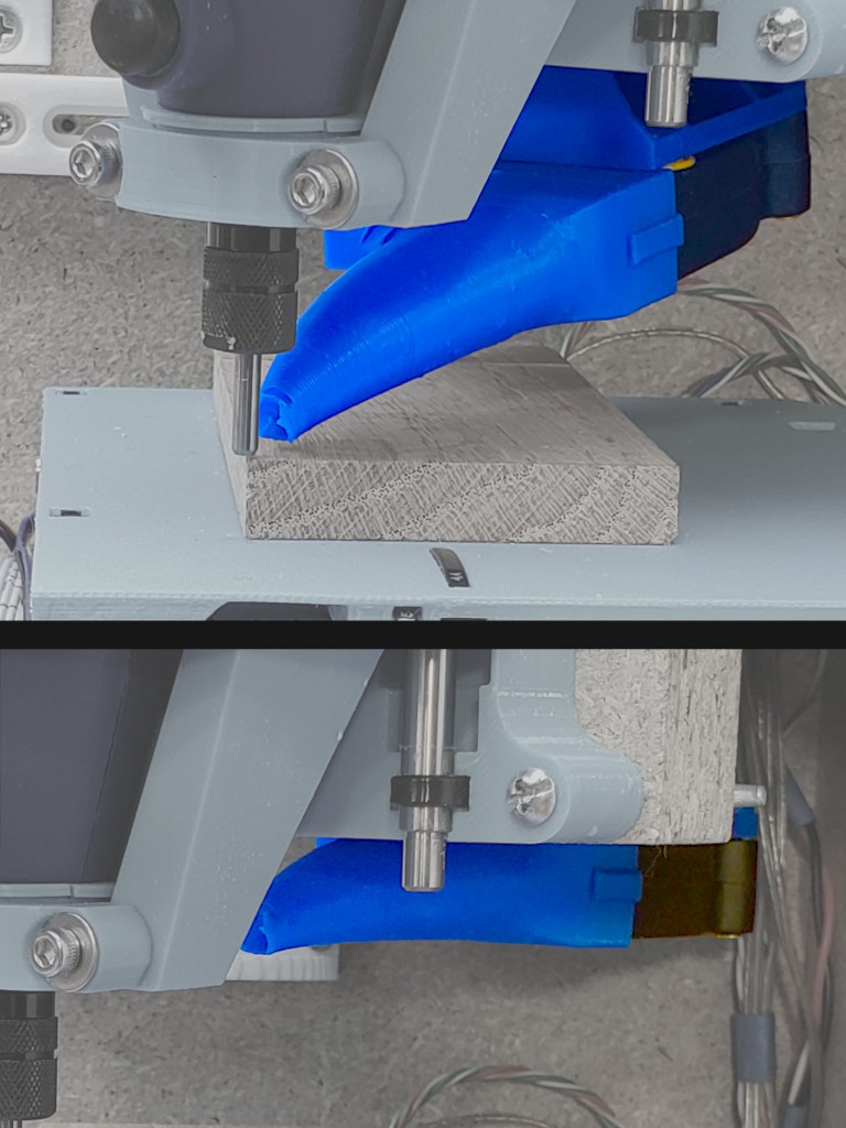
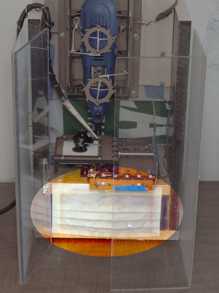 Sticking a vacuum hose into the same space would probably work too -- to the extent that a given vacuum's filtration works -- but I'm going with running a vac briefly to clean up vs. continuously while operating (and I can use a cordless hand vac).


 Cedric Anné
 CriptasticHacker
 Quinn
Quinn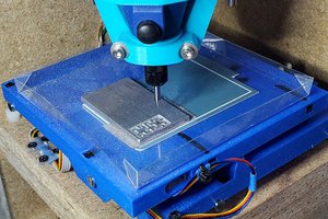
For the spindle, my machine uses a 5010 brushless DC motor turning a 5mm rod that goes down into a wood block with a big 16x35x11mm bearing at the bottom, which fits around an ER11 extension chuck. Having the bearing so close to the bit gives excellent rigidity. It does cover up the wrench flats in the chuck, but instead of using two wrenches you can just grab the rotor of the motor while you tighten the ER11 nut with a wrench.
But the 5010 motor needs an ESC, and a servo tester to tell it what speed to go, and some kind of power supply to provide appropriate DC voltage for it, so that may increase the machine size beyond what you save with the smaller motor. Also the big bearing on mine gets hot and I'm not sure why. It really should be an angular contact bearing, but unfortunately there are none available with 16mm ID. I'd like to use a C10 ER11 chuck (10mm integral shaft rather than an extension chuck) with an 7000AC (10x26x8mm) angular contact bearing, but then the motor can't turn it directly like the 5mm shaft.
Regarding overall machine design, one thing you might consider is making it usable as a little drill press. Very handy to have around if you don't have space for a big one. Try to make it so you can at least get a 2x4 through with enough side-to-side room that you can drill a hole anywhere in it. And put a manual crank on at least the Z axis. But manual cranks on all 3 axes are wonderful to have, even just for positioning after you get the workpiece clamped down. Also nice being able to do simple milling operations without having to mess around with the computer.