 Paul McClay
(12 Apr '24 update: add brass pic; update 'UX' gif)
Hackaday Prize 2023 finalist! Thank you judges!
Minamil 3dp is another little CNC mill. This one uses 3d printed parts, which give (at least) two advantages:
- probably more people can 3d print parts today than can laser cut parts
- much easier assembly vs. building 3d structure from 2d parts
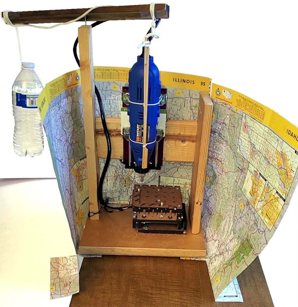
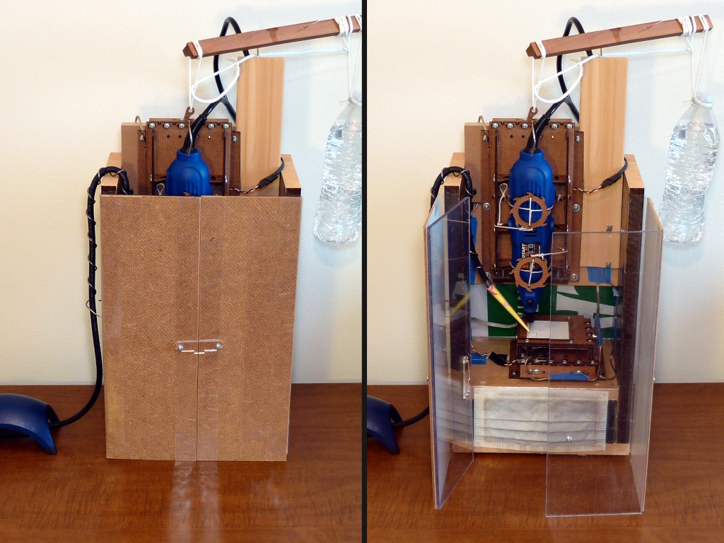
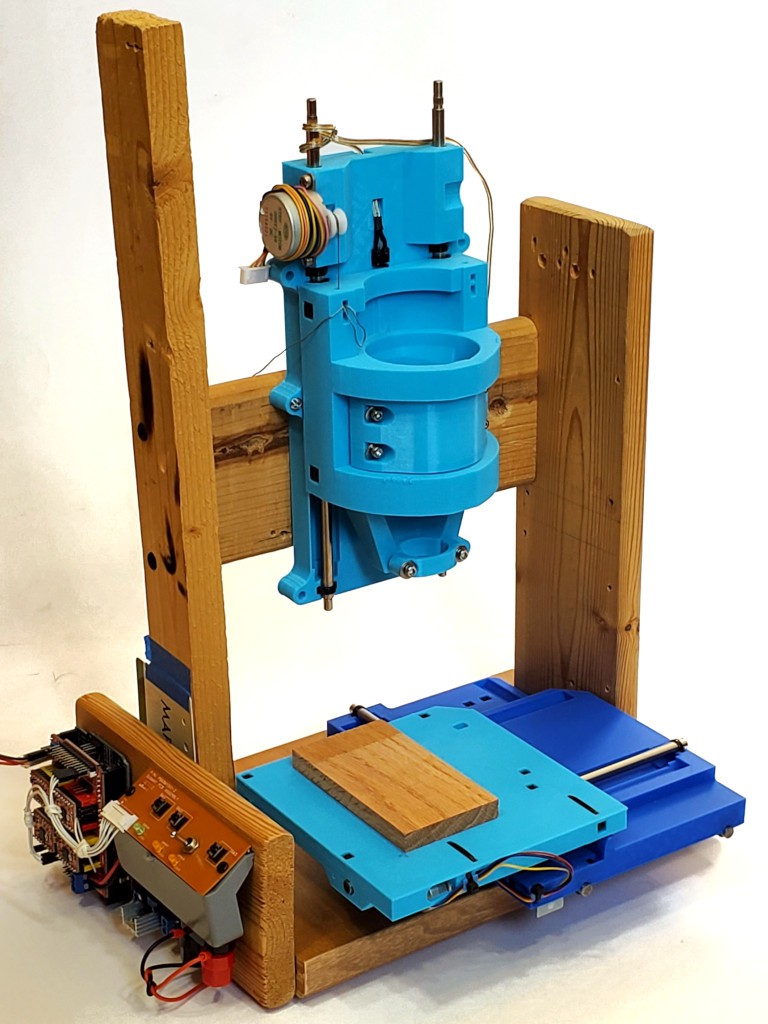
While not at all necessary to make the CNC parts work, a little more work put into the frame/enclosure can make a more practically usable result. The example shown below also shows:
- a completely new configuration of the integrated enclosure concept relative to earlier work
- more complete actual accomplished integration of accessory stuff that could be integrated but previously wasn't
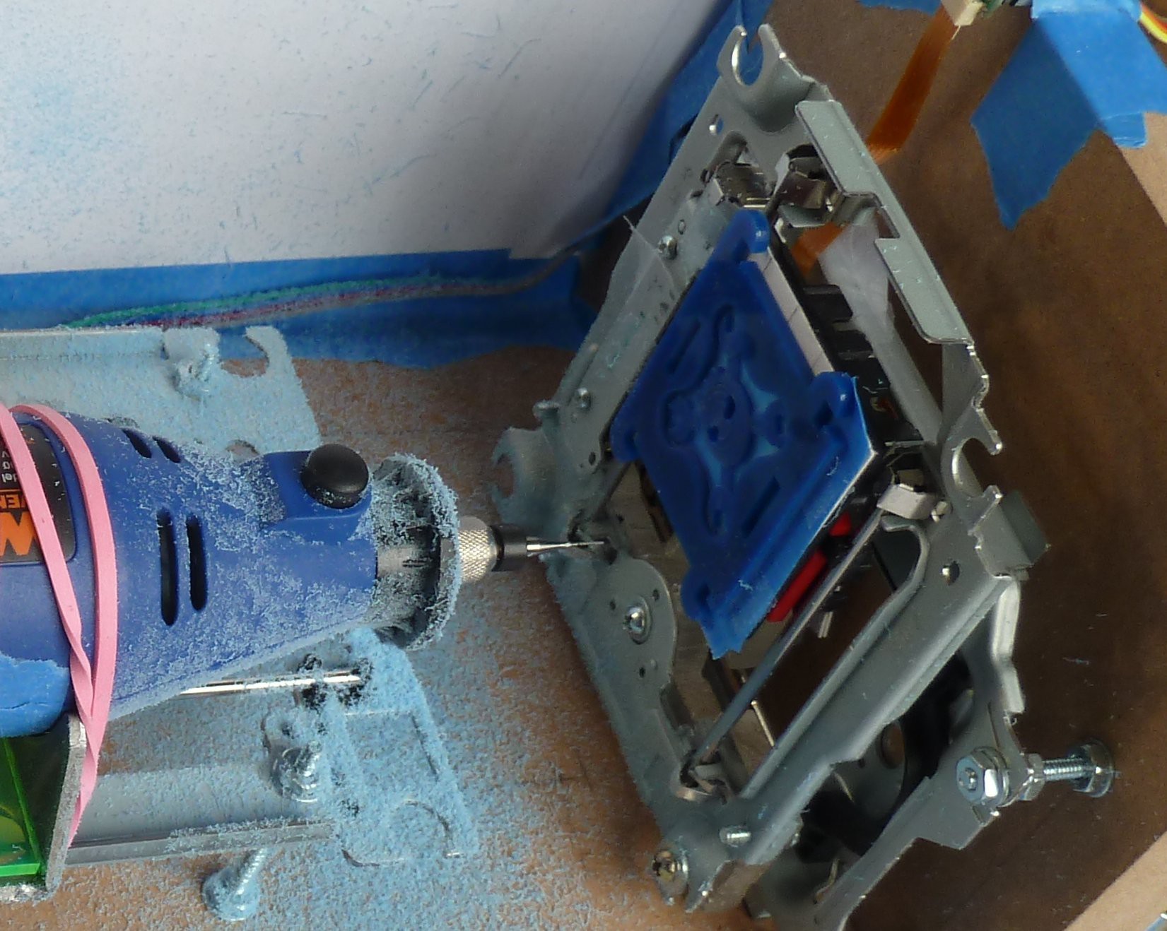
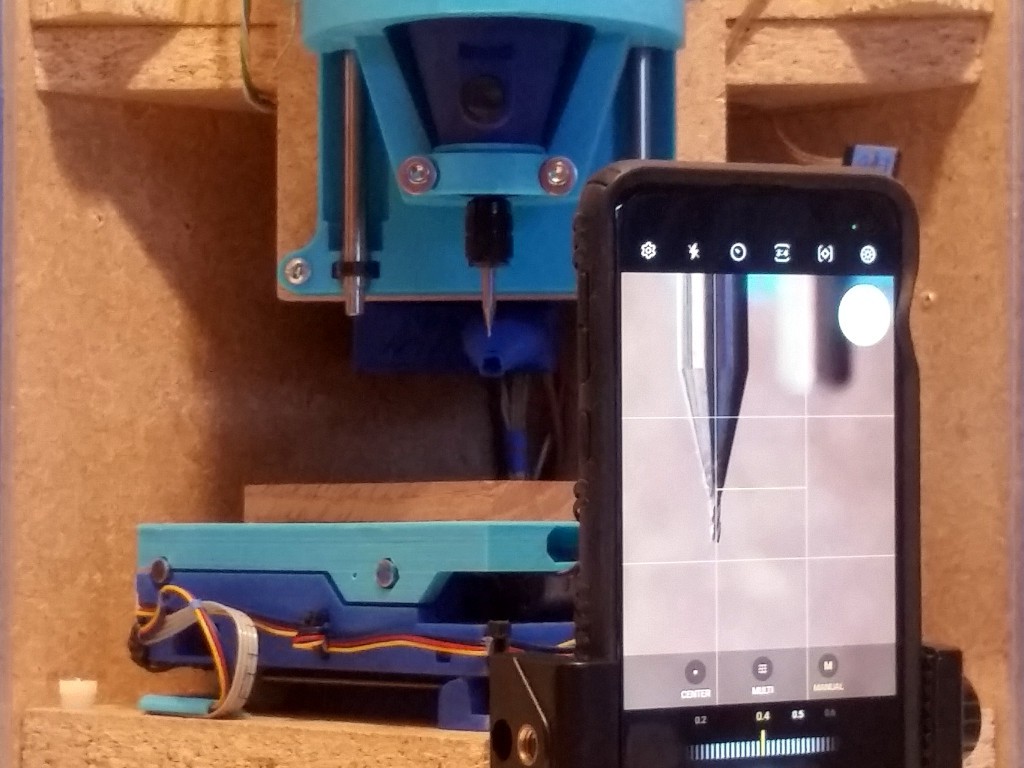
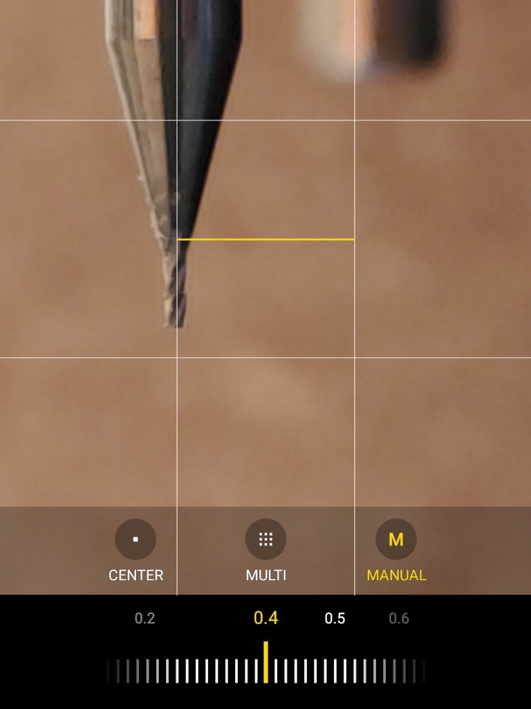
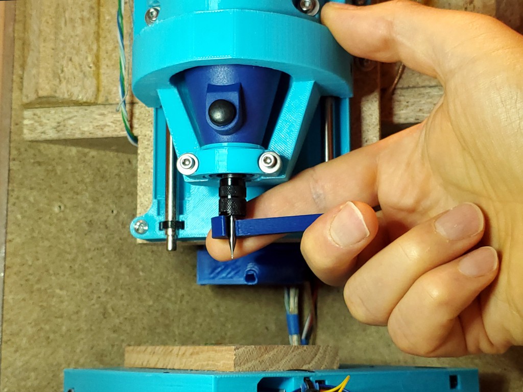
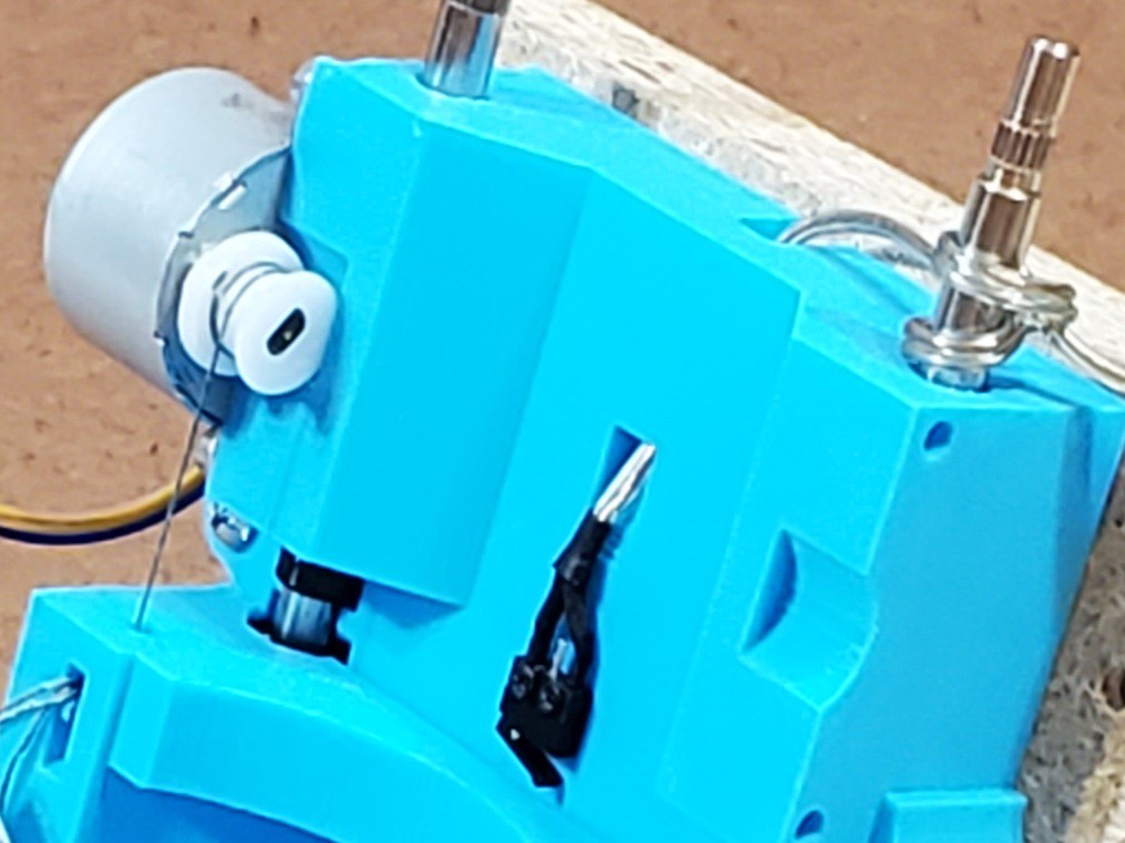
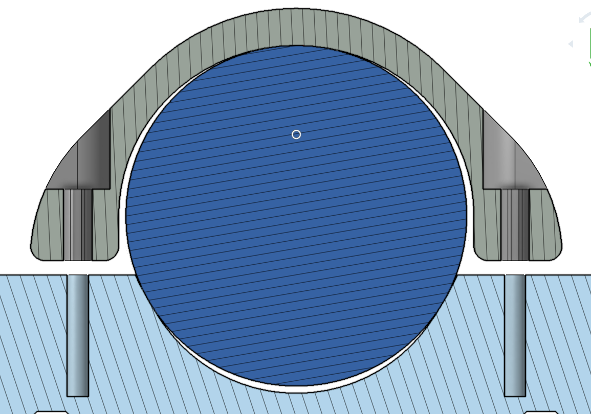
And a little side show that makes this work, that I haven't seen elsewhere, and that might help anyone trying to do fine work with a cheap rotary tool: reducing runout.
Cut small stuff from useful materials:
Up to 75mm x 75mm x 50mm.

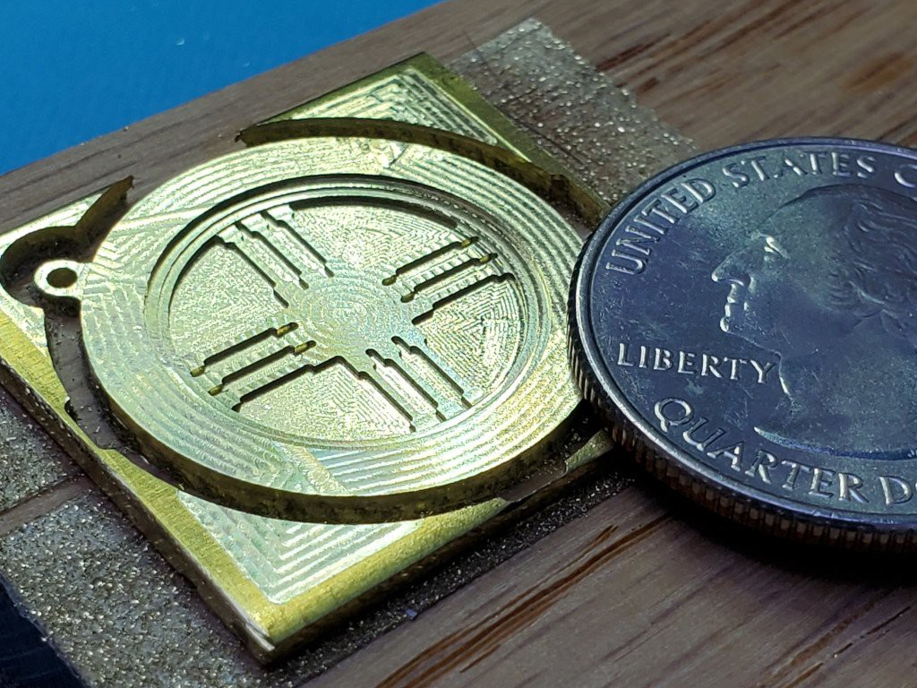
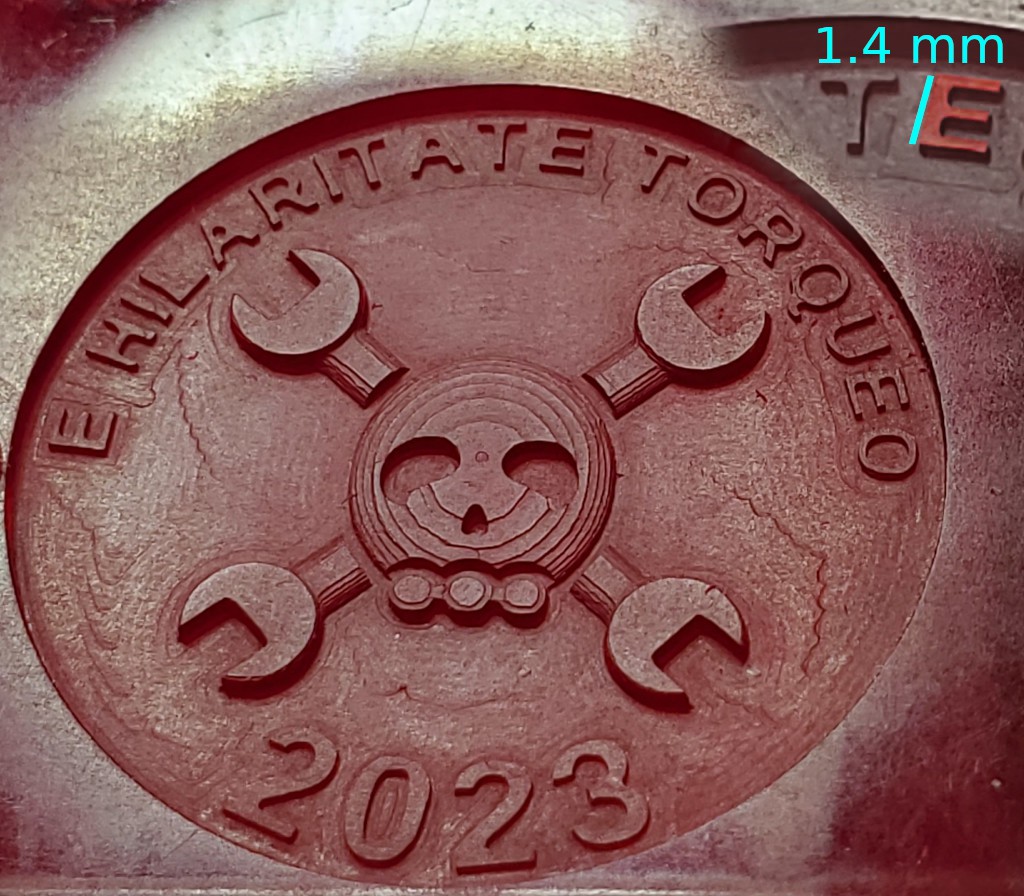
Figure cut from brass flat bar using 1 mm (0.039") and 0.015" (0.38 mm) flat endmills.
nevermind the paint -- that's a different learning curve.
...and yes, I will mix units horribly in this project. it will be ok, we're not trying to land on another planet.
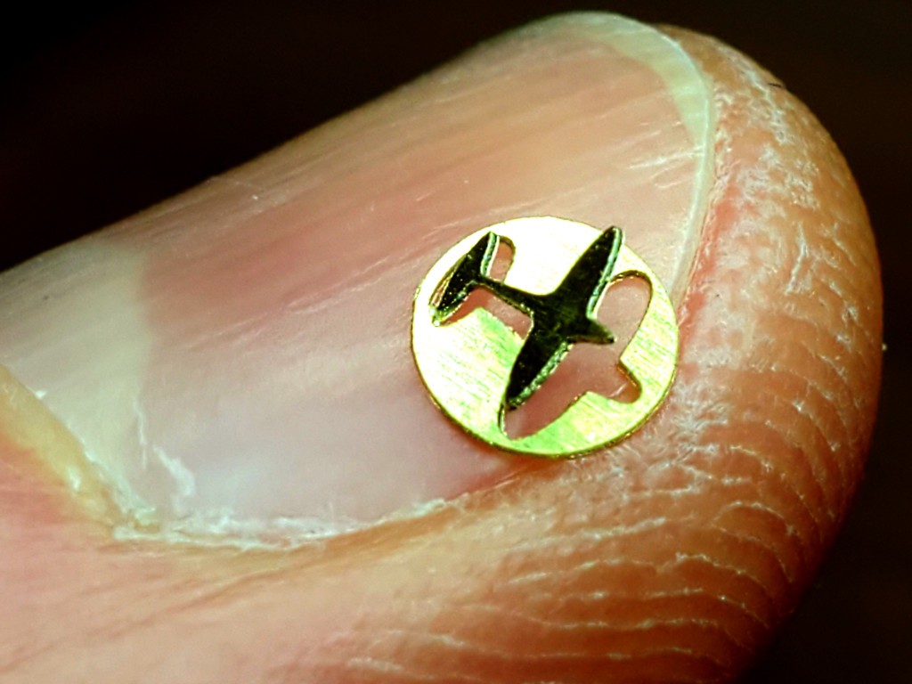
Little airplane in a 4 mm disk cut from brass shim stock with a 0.1 mm V bit.
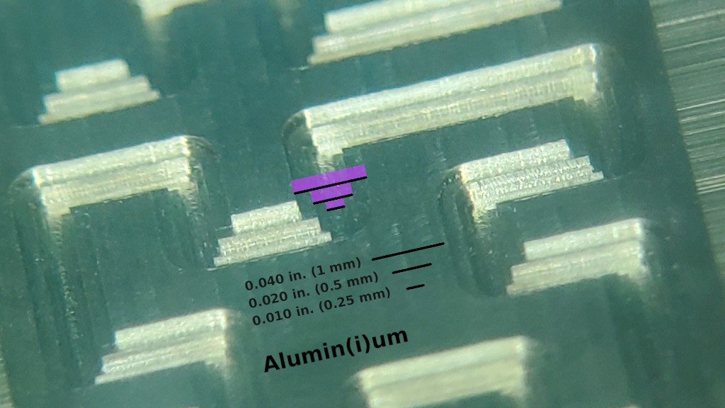
Sharp, accurate features in Aluminum with tiny cutters down to 0.010" (0.25 mm). This pic is a backlash test pattern for the "big" cutter that I repeated with the smaller cutters because new toys.
This short video is kinda neat but doesn't really add much so I'll link instead of embed so hopefully it won't slow down your first scroll through this stuff:
Mill circuit boards for fine-pitch components:
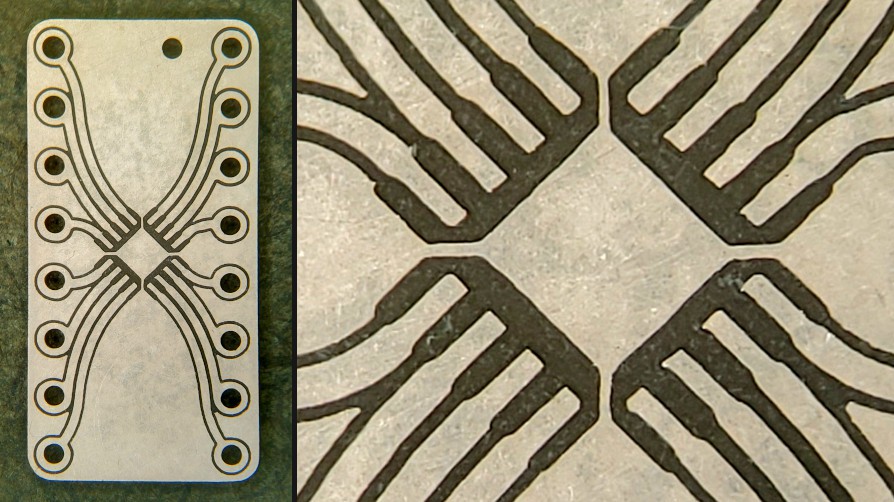 Breakout board for 0.5mm pitch QFN-16.
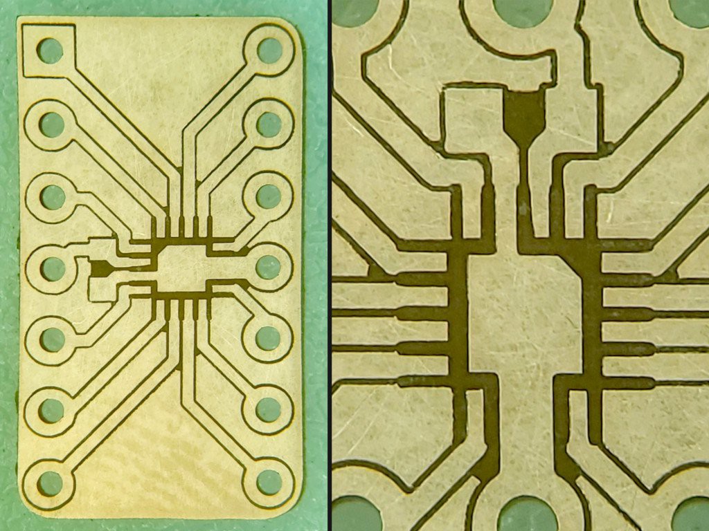
A more specific 0.5 mm pitch QFN-16 breakout for TLV7044 with supply bypass closer to the chip and pinning like the DIP & SO packaged parts. For a different project. Hopefully I'll be able to replace this pic with a populated board "soon"...
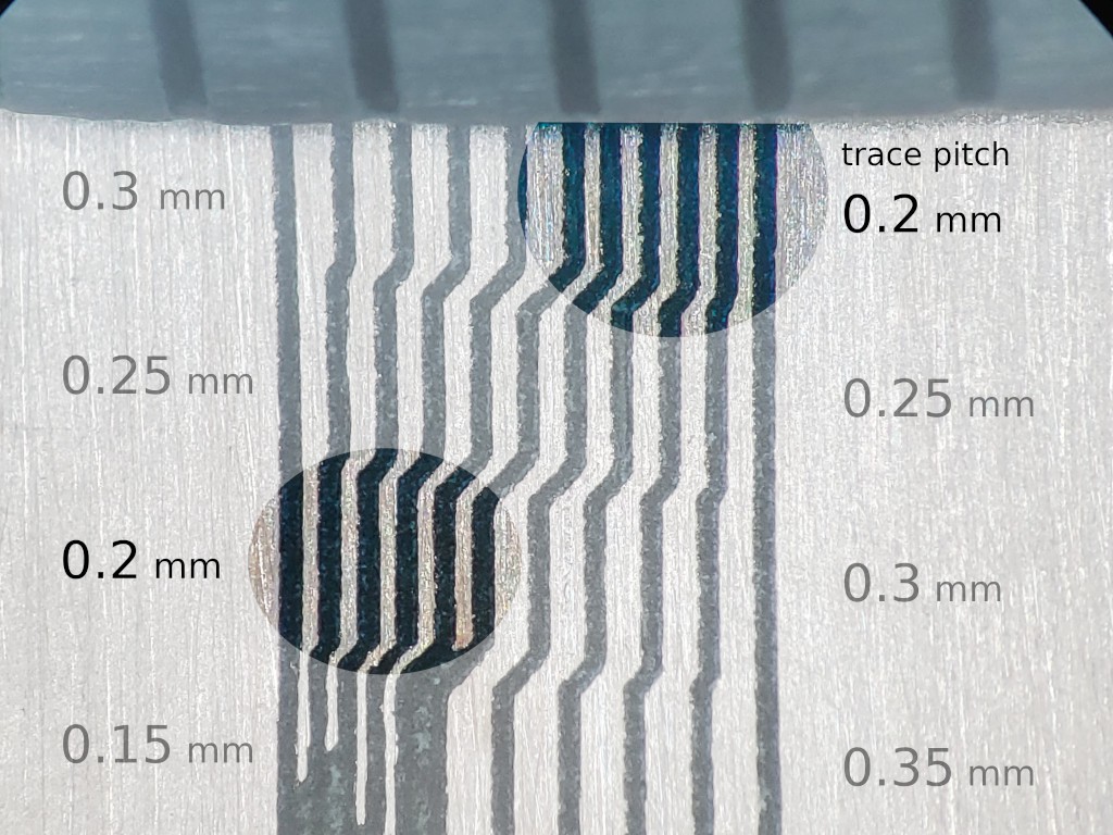
Isolated traces down to 0.2 mm center-center pitch with a 0.1 mm V bit.
But that's all flat stuff :-/
Yeah. I've been working on the tool instead of making stuff. But check this out:
First I'll show this little bevel gear,...
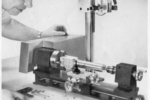
... because the "3dp" 3d printed mill that is the object of this project actually for real cut that gear at MRRF. So I hope you'll accept some parts cut by the earlier laser-cut version of this CNC as an illustration of capability:
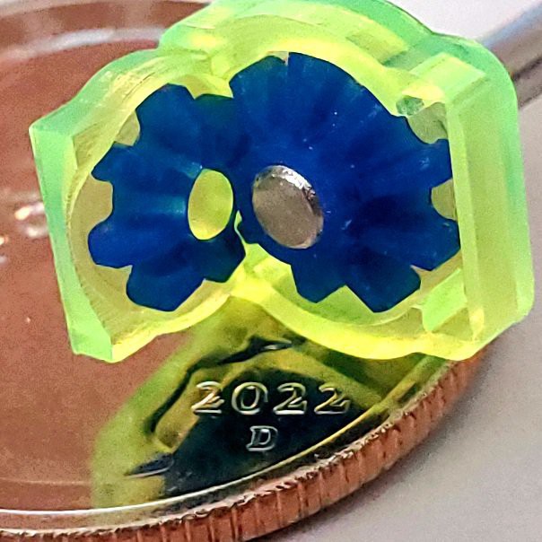
Spider gears and structure parts for a little differential with a US "quarter" coin for scale.
The spider gear assembly in the complete differential is smaller than my fingernail. There's a <4 min. video about that over in the "2dc" project but it's old work and too much about the earlier laser-cut design to include in this project.
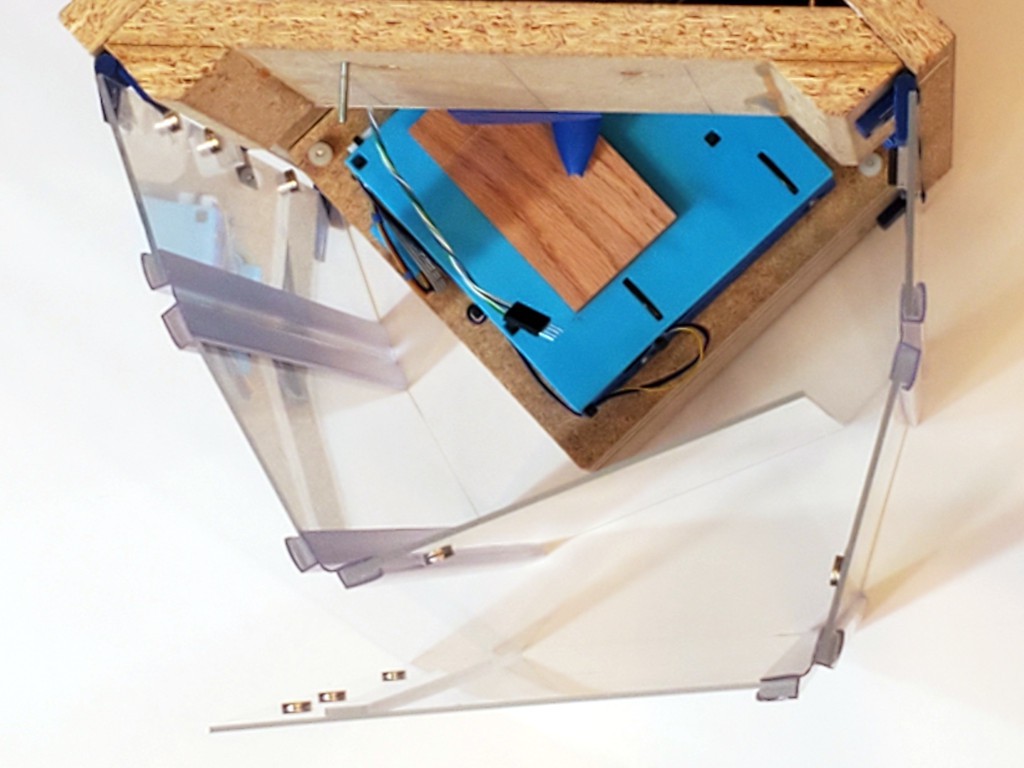
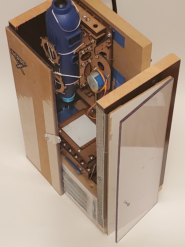
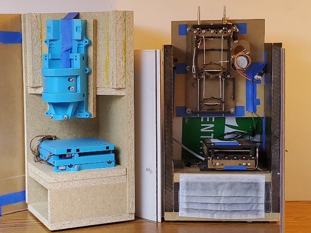
Packaging for UX
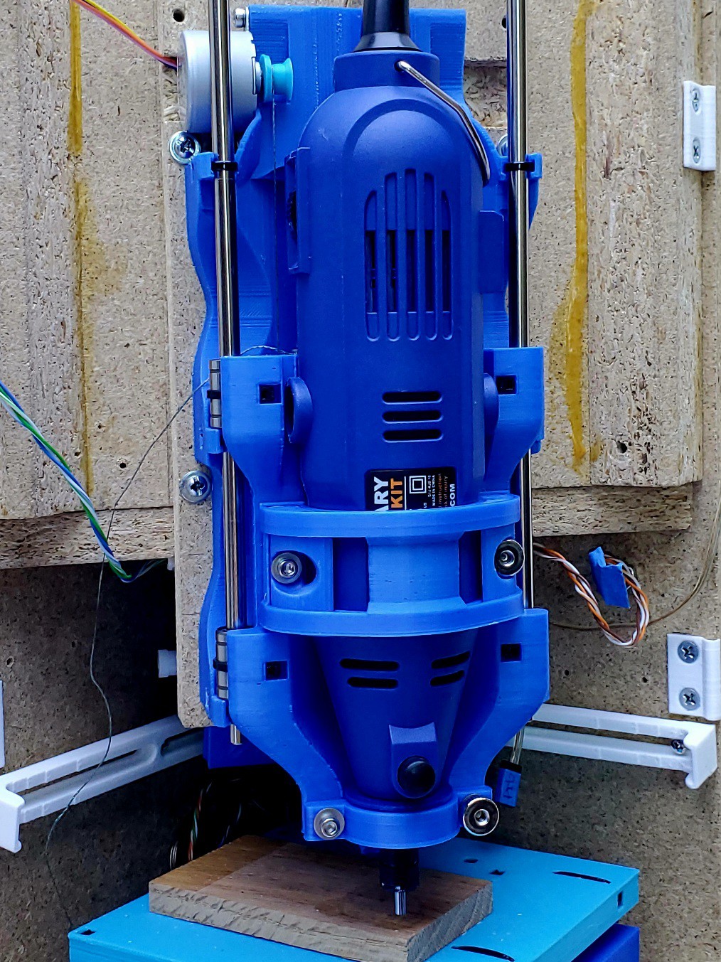
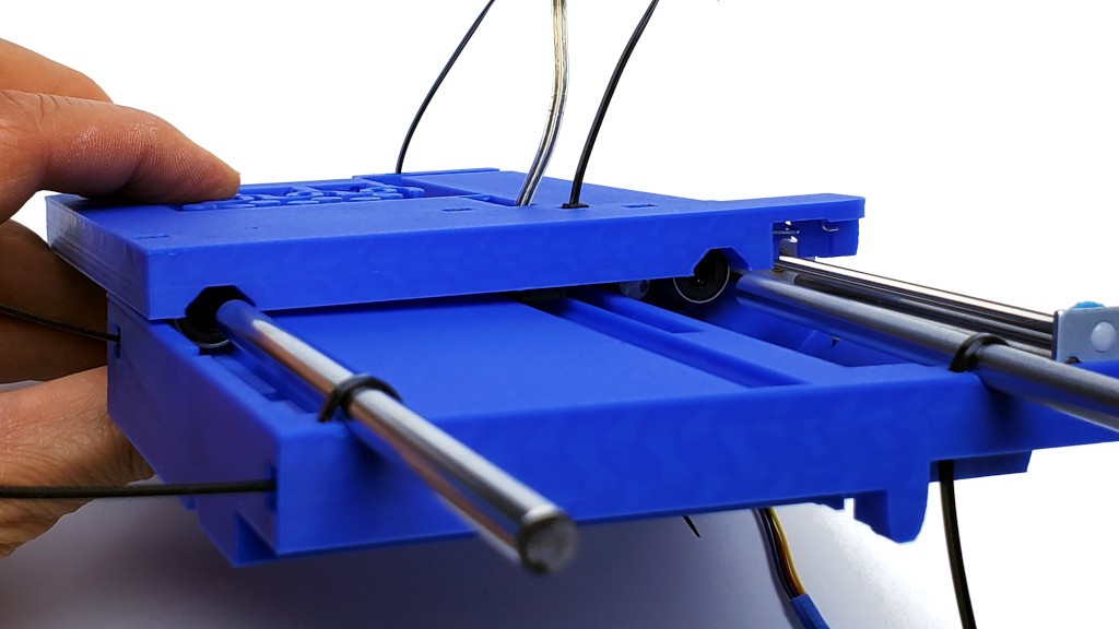
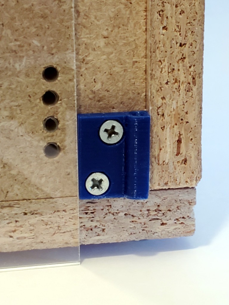
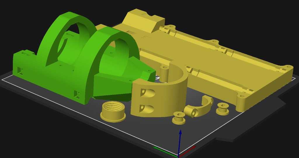
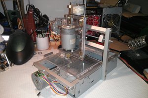
The CNC mechanics consist of an XY table and a separate Z axis. The two parts need some sort of frame to hold their positions relative to each other. The frame can be very basic. But I want to use my machine in a smallish urban condo with no "shop"-like space. So I've put a little more effort into the frame and packaging..
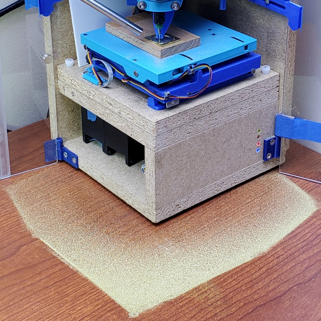
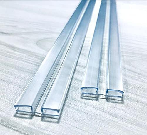
The "telescoping" slide design allows very compact non-operating footprint.
More about packaging -- which is already obsolete because I haven't yet written up several improvements like cleaner DC supply and integrated logic-switched AC for the dremeloid.
Interested?
To build your own, start here.
To scan log entries, ToC here.
Spun off from #Minamil: a minimal CNC mill and companion to #"Desk Accessory" CNC Milling Machine.
This project encompasses 2 projects. And a half.
- very small and low cost 3-axis CNC mill/router mechanics
- functionally like #Minamil: a minimal CNC mill but 3d printed instead of laser cut
- needs a frame and the frame can be very simple, or...
- #"Desk Accessory" CNC Milling Machine ...


 Stefan Lochbrunner
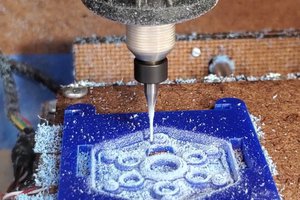
 Jose Ignacio Romero
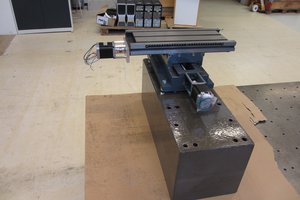
I like this project and have a recommendation: change the stage so that each axis travels from -50% to +50% (of it's width) from it's original position. Exceeding 50% increase the chances of tramming issues.