Close
0%
0%

Circuit Golf: Electronic Dice Edition

Creating Electronic Dice with the least number of components in the most obscure technologies

timTim
Similar projects worth following

Circuit golf is a type of recreational circuit design competition in which participants strive to achieve the smallest possible design to solve a certain problem using a technology of choice*.

Building electronic dice is a rite of passage for every electronics tinkerer. Most likely you assembled it as a DIY kit sometime years ago. But was that really best way of doing it?

The goal is to create an electronic dice circuit with as few components and/or the most obscure technology possible. This is supposed to be an ongoing friendly competition. Just add your entry as a log. Anything goes from a technology point. Simulation is ok, when it is reasonably linked to something that could be made in reality. But obviously the real thing is always better.

*Totally stolen from here https://en.wikipedia.org/wiki/Code_golf

https://cdn.hackaday.io/images/7896311639299756265.file-1639299756245-763961774Two examples found on the internet

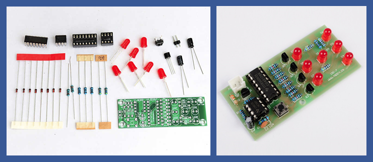
An electronic die typically consists of these elements:

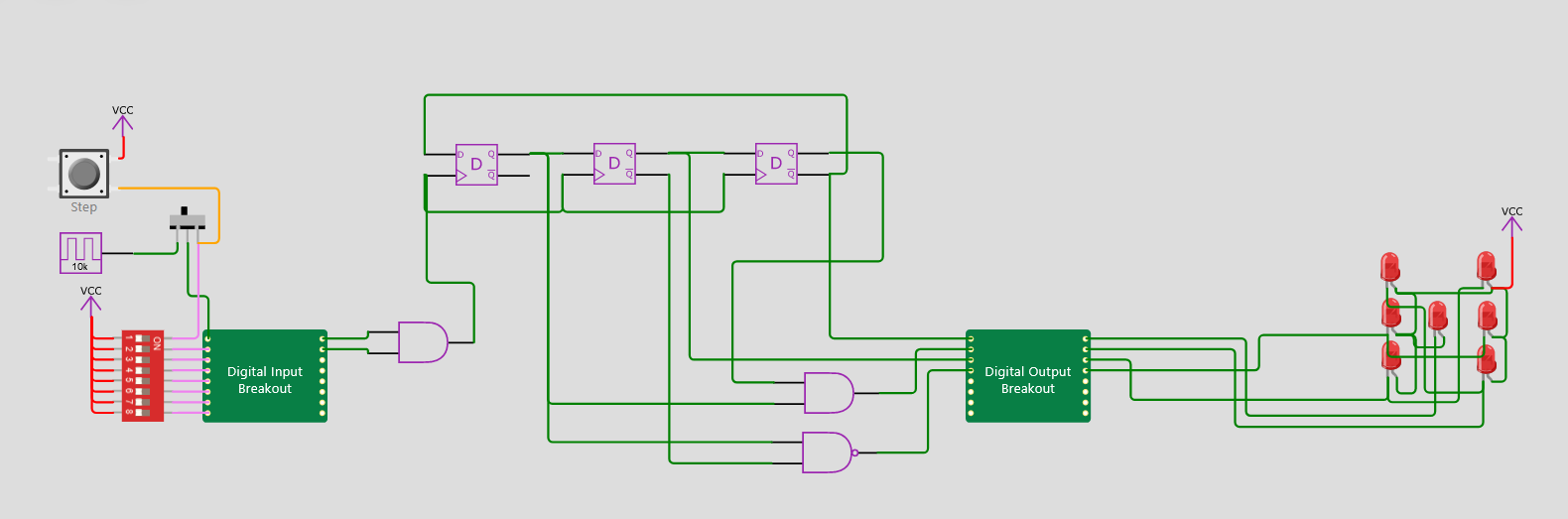
  • An oscillator that can be enabled to "roll" the die
  • Some kind of counter
  • An encoder to convert the states from the counter into the "pips".
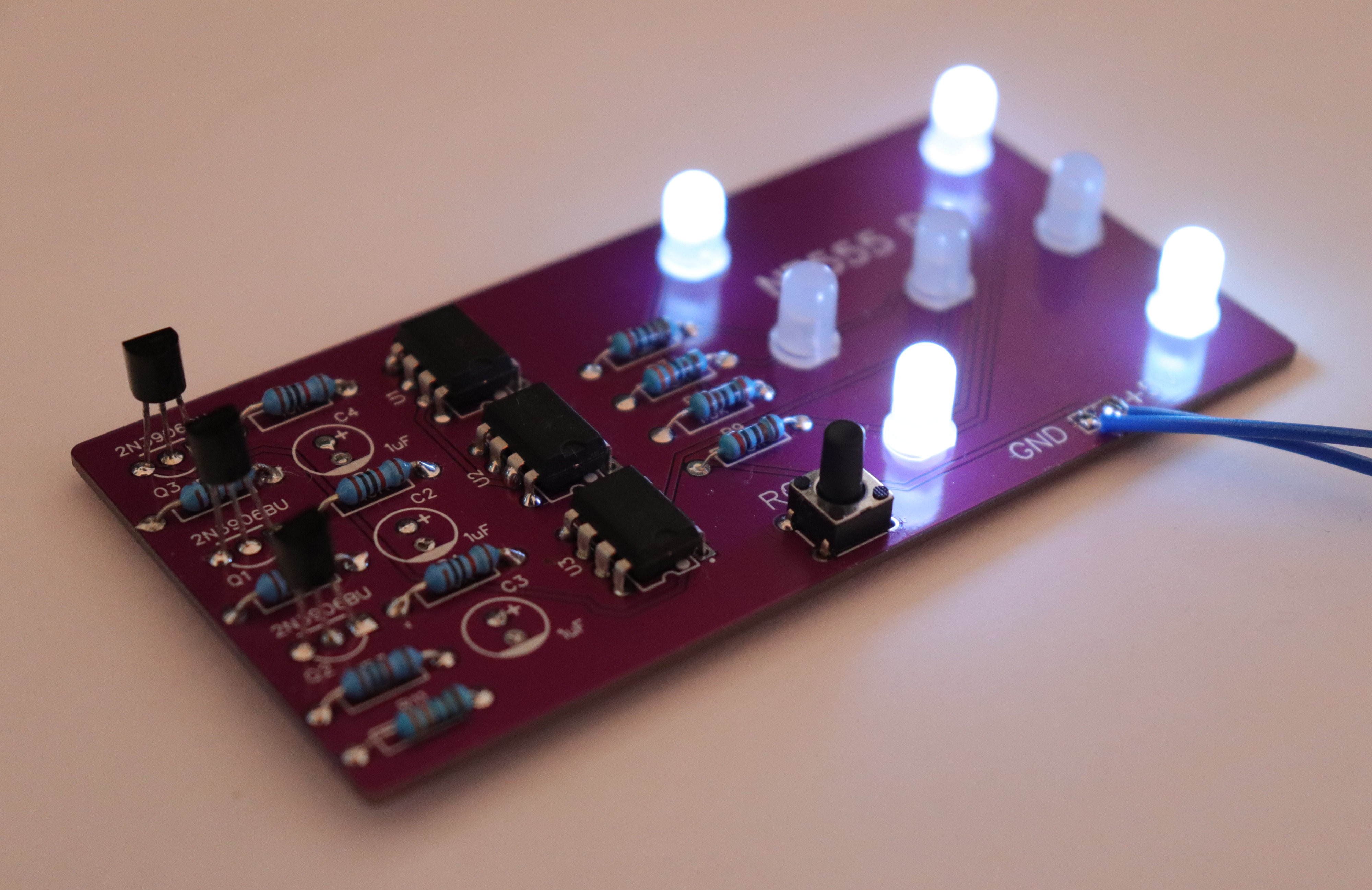
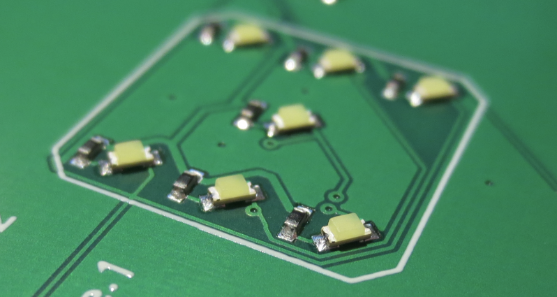
  • 7 dots / "pips". These are typically LEDs, but why not use something else?

List of entries

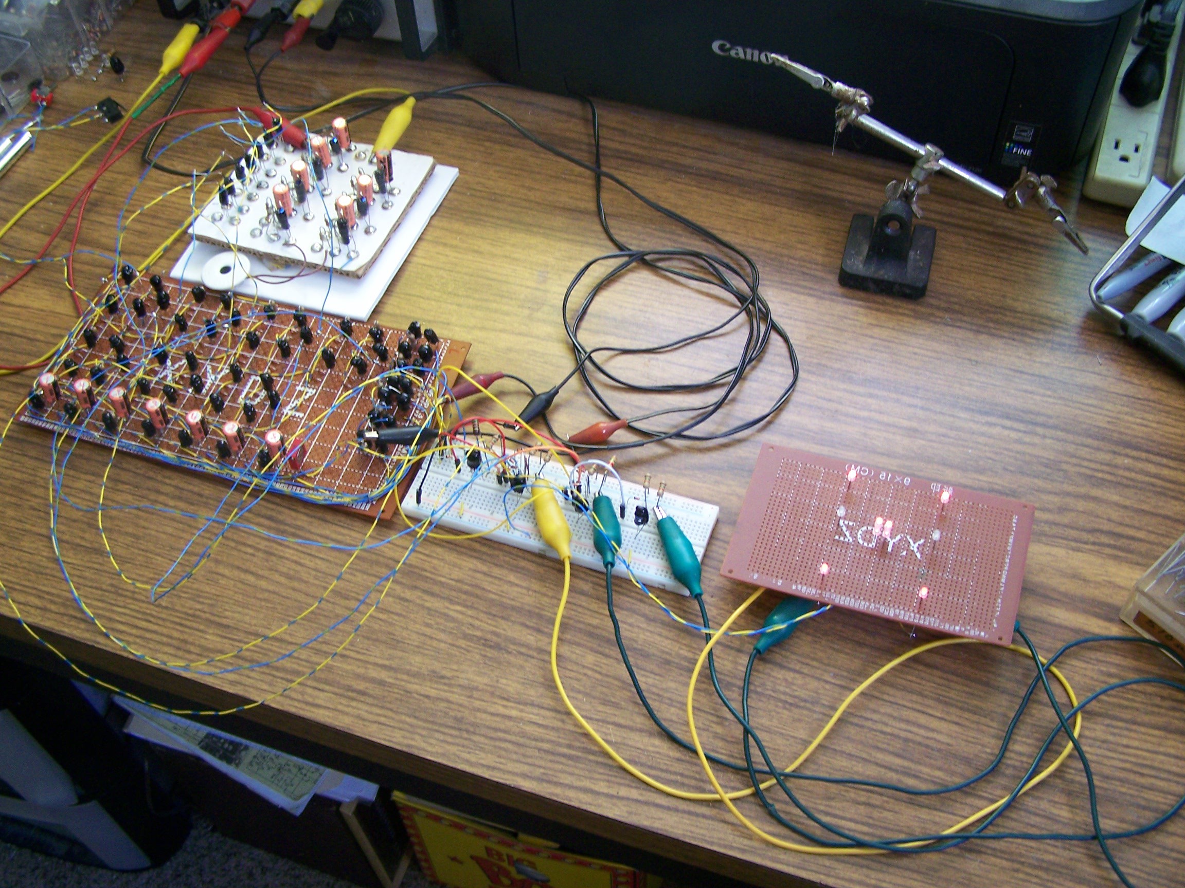
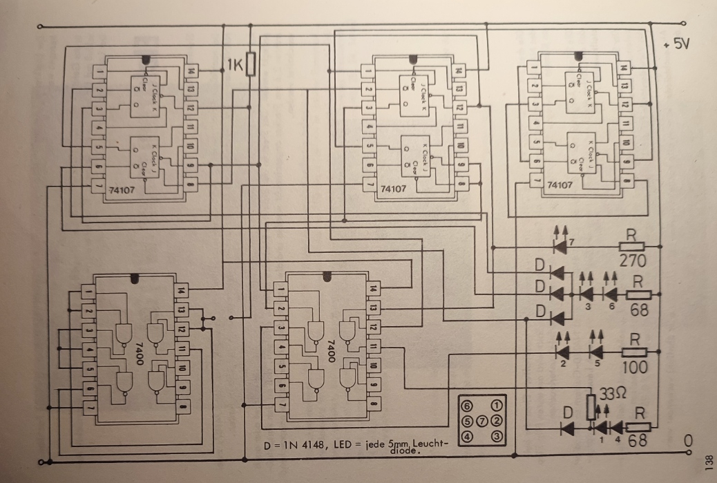
#001 A classic 74XX TTL implementation (found in a book)

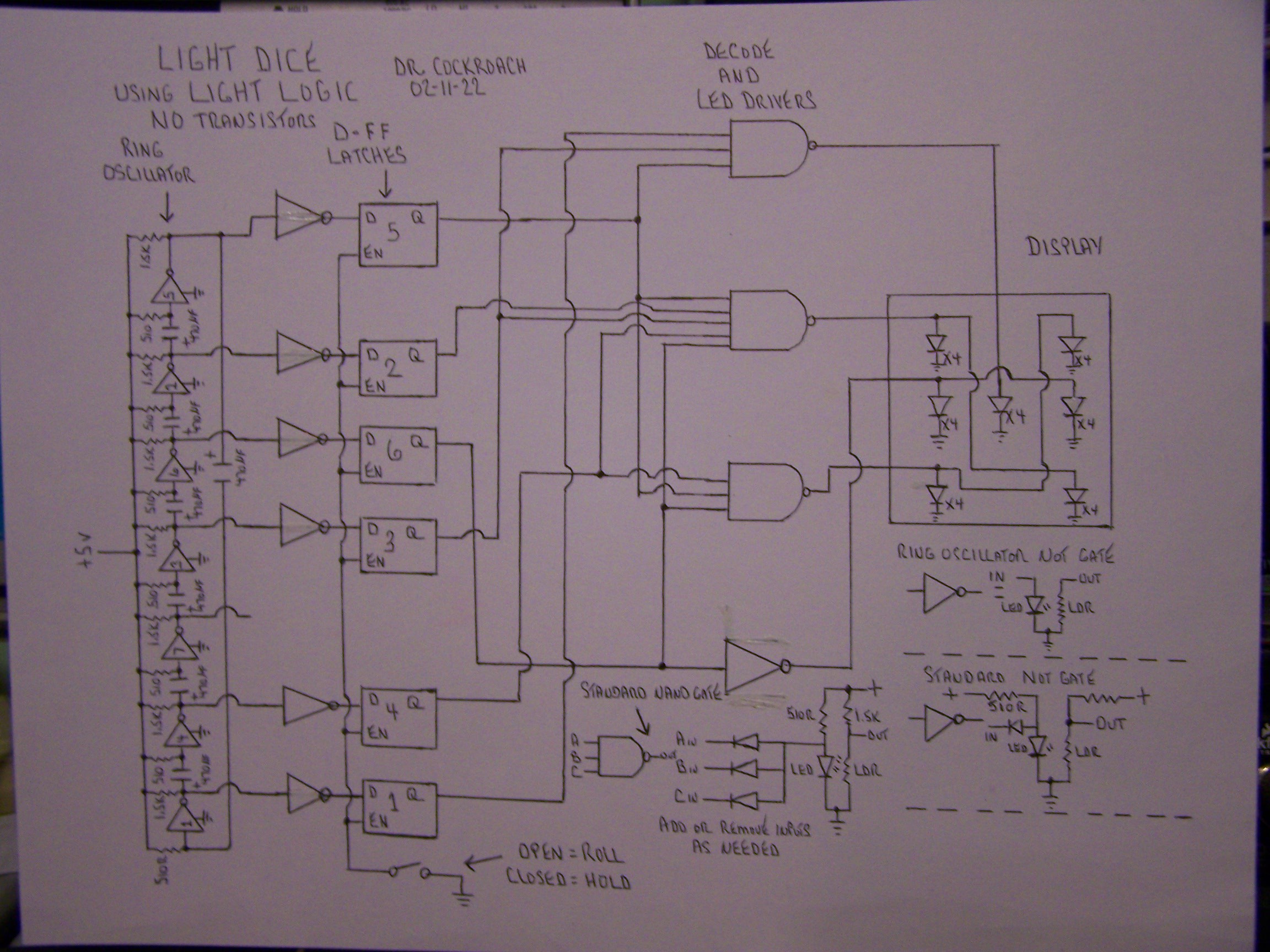
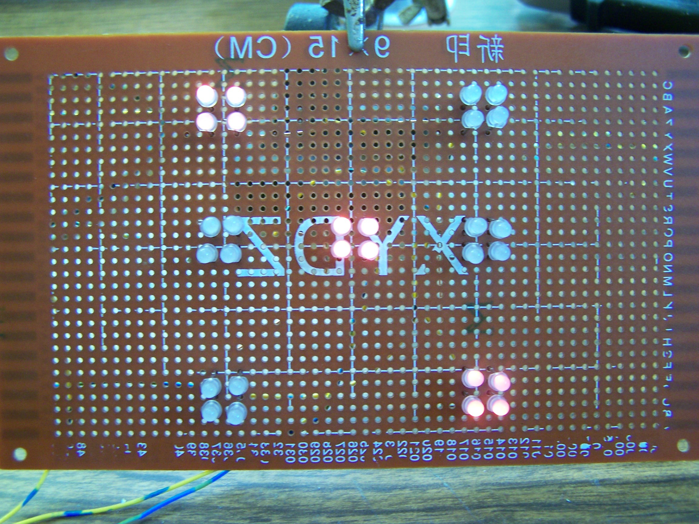
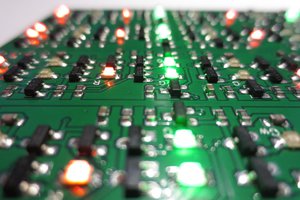
#002 "Light Dice" in transistorless Light Logic by Dr. Cockroach

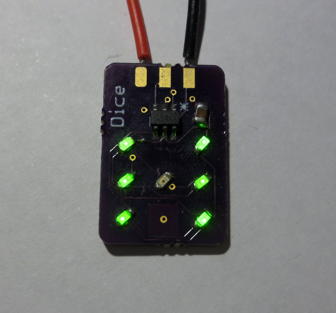
#003 Dice10: The smallest possible implementation with a MCU by Tim

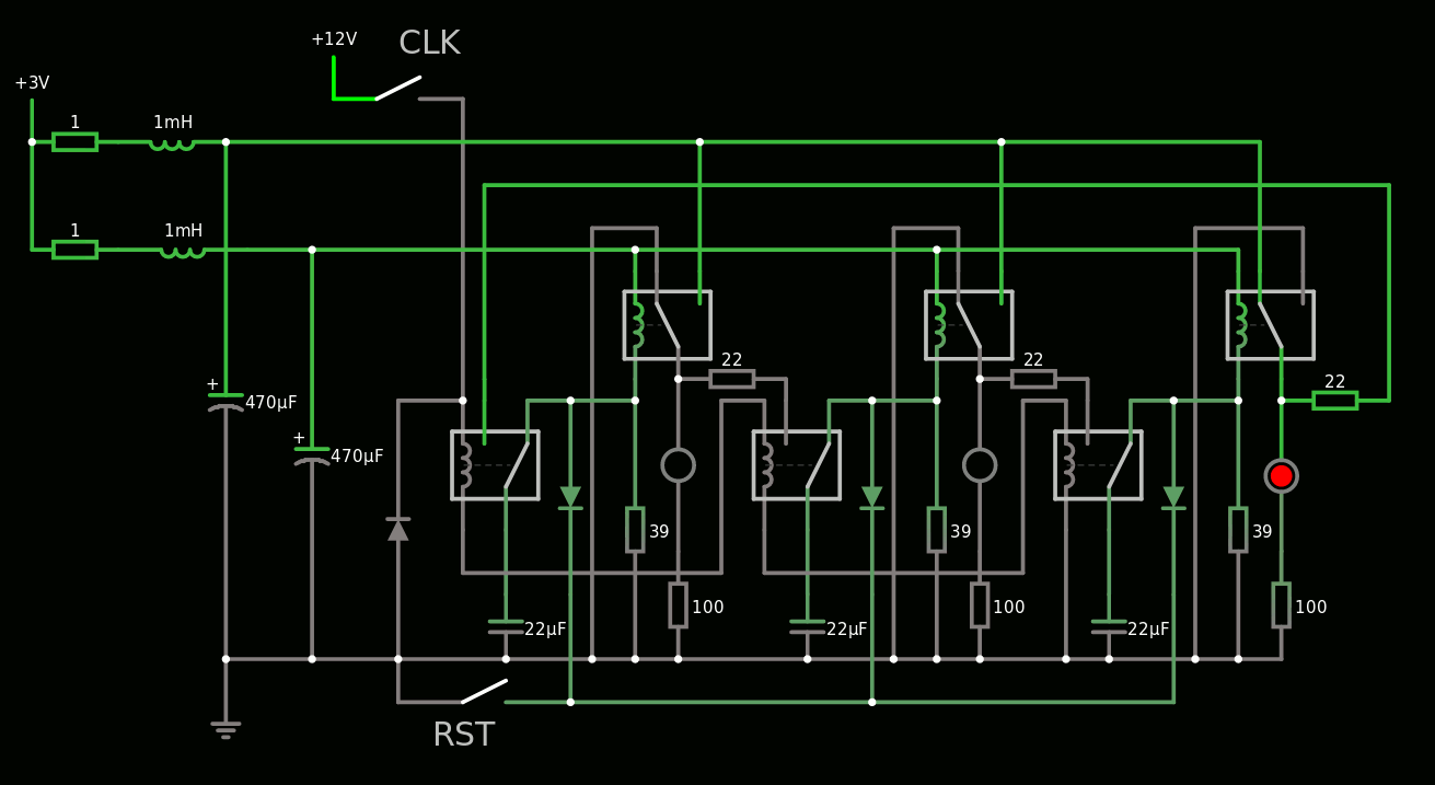
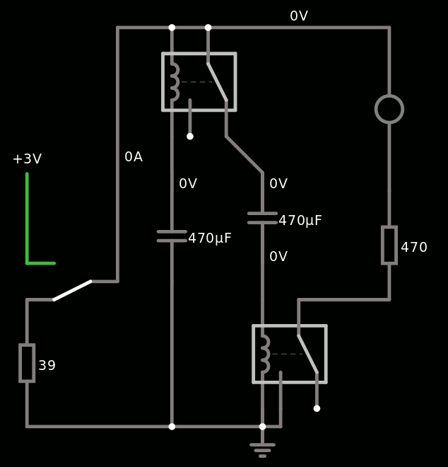
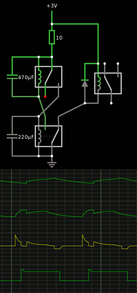
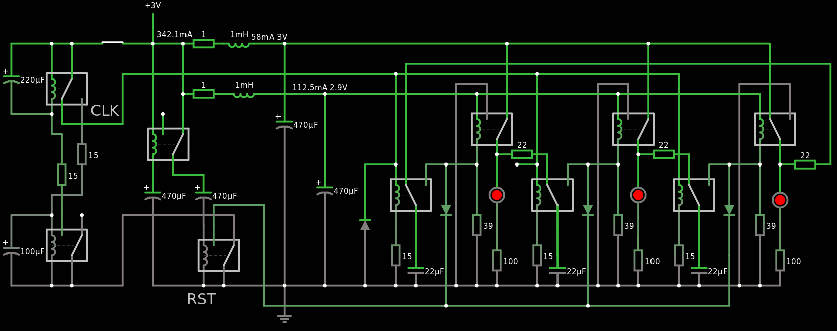
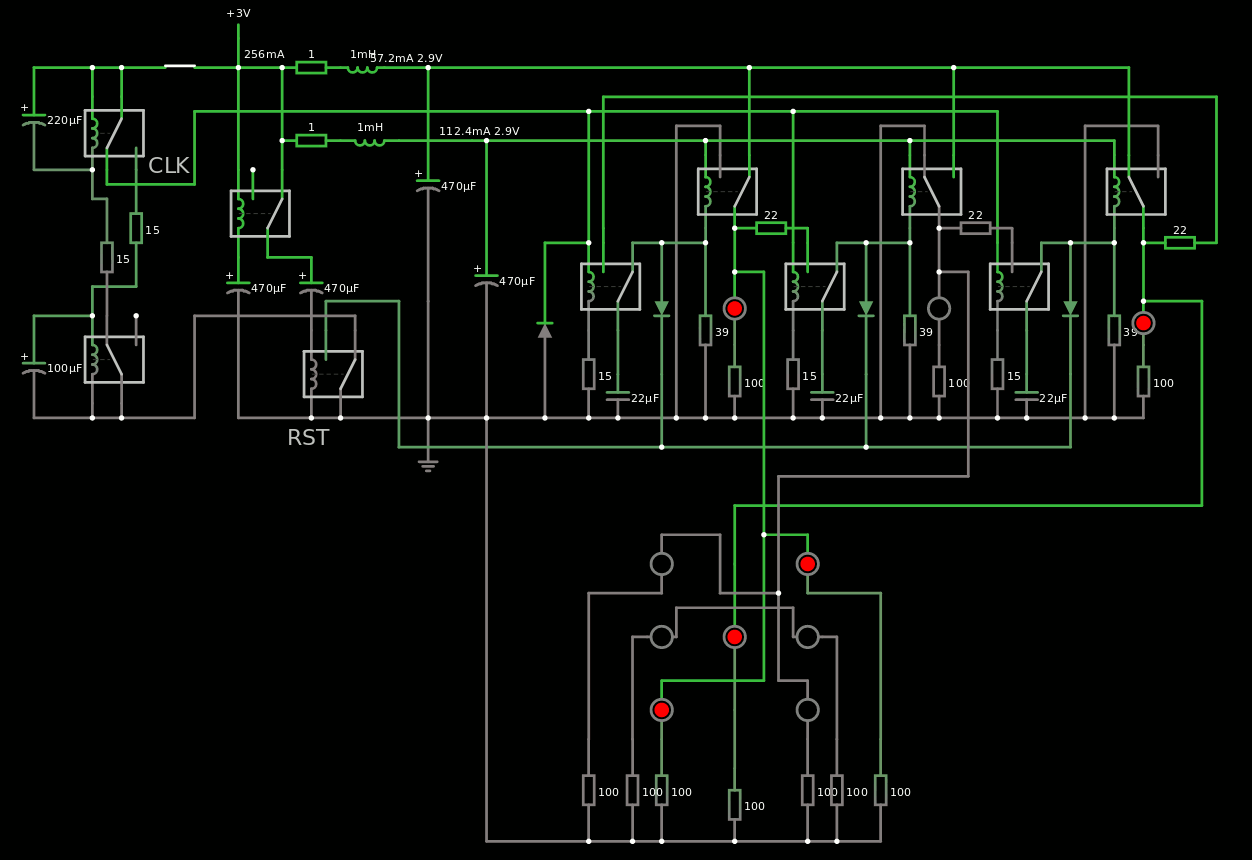
#004 Dice based on low-voltage relays by Yann

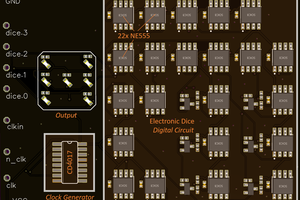
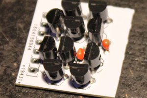
#005 Dice3904-8: Smallest(?) implementation using bipolar logic by Tim

#006 Dice555-3: Very smallest design based on NE555  by Tim

#007 TinyDice for TinyTapeout - Dice on an ASIC  by Tim

SCH_3NE555die_2022-12-21.json

EasyEDA schematics for NE555 die

JavaScript Object Notation (JSON) - 61.43 kB - 12/21/2022 at 06:59

Download

PCB_PCB_3NE555die_2022-12-21.json

EasyEDA PCB Layout for NE555 die

JavaScript Object Notation (JSON) - 479.59 kB - 12/21/2022 at 06:58

Download

Schematic_3NE555die_2022-12-21.pdf

PDF schematics for NE555 die

Adobe Portable Document Format - 53.62 kB - 12/21/2022 at 06:58

Preview
Download

  • #007 - TinyDice - Dice on an ASIC

    Tim09/03/2022 at 10:24 4 comments

    Details

    Entry by: Tim

    Technology:  Skywater 130nm CMOS

    Size: 3 DFF, 1 NAND, 1 AND, (1+ AND for clock gating)  ~ 10x10µm² on the IC.

    This is a submission for tinytapeout that combines 500 very tiny digital designs into a single ASIC to be manufactured by eFabless open shuttle program. The maximum allows space on the die is 100x100µm² and the design can use 8 inputs and 8 outputs. Both, of course, still rediculously oversized for a minimized electronic die!

    Read more »

  • #006 - Dice555-3: "End-game"?

    Tim02/15/2022 at 21:25 6 comments

    Details

    Entry by: Tim

    Technology:  NE555 freestyle

    Size: 3 NE555, 3 Transistors, 11 Resistors, 3 Capacitors, 7 LEDs

    After squeezing the last diode out of the discrete transistor implementation, let's try to optimize the circuit even further. It's time to revisit the NE555 as a main component of electronic dice, because both somehow belong together. I designed an electronic die based on NE555 logic earlier, taking a whopping 21 NE555. This was optimized to only 12 NE555 later, by introducing a Johnson counter. Now let's improve on that. This approach takes a lot of inspiration from the light dice by Dr. Cockroach.

    Read more »

  • #005 - Dice3904-8: Minimal Transistor Based Dice

    Tim02/12/2022 at 11:05 4 comments

    Details

    Entry by: Tim

    Technology:  Bipolar/Diode logic freestyle

    Size: 8 Transistors, 8 Diodes, 25 Resistors, 8 Capacitors, 7 LEDs

    (The photo is just a placeholder for later hardware)

    Architecture-, Logic- and Circuit-Optimization

    What is the minimum number of discrete components required to implement the electronic dice functionality? The technology of choice is bipolar logic. Let's try to identify a systematic approach for reduction of system complexity. First, we will look at the system level, then logic level implementation and finally a circuit implementation.

    Read more »

  • #004 with old low-voltage Russian relays

    Yann Guidon / YGDES02/10/2022 at 18:35 7 comments

    I know I know it's only a sim. For now. Because Falstad's CircuiJS is getting better at simulating relays and such. So bear (and raccoon) with me for a while, because it will be a snap to implement for real, right ? :-P

    As usual I design this around the old RES-15 relays, SPDT, with the following parameters in circuitjs:

    • Inductance : 28mH
    • On resistance: 1m ohm
    • Off resistance: 1G ohm
    • On current : 50mA
    • Off current: 30mA
    • Coil resistance: 38 ohms
    • Switching time: 3ms

    The 3ms is an approximation but it gives an idea of the speed that the circuit can reach.

    The heart of the system is a 3-stage Johnson counter, made of 3 DFF which use hysteresis for latching. Each DFF has a SPDT capacitive temporary latch to separate each stage. That makes at least 10ms overall, 100Hz max.

    You can even play at home online !

    The clock though is a different beast. It must be fast enough but not too fast or the JC can't follow and will end in an invalid state.

    But while seeking a suitable system, I managed to find an innovative (?) Power-On-Reset circuit !

    It has some interesting features :

    • it waits for a first period, while the power supply's capacitors charge.
    • it then send a pulse for another period
    • the timing depends on the power voltage, the capacitance and the relay's resistance
    • there is no shorting of the capacitors to the ground, which damages the relay's contacts
    • uses only electrolytic capacitors for high storage, easier to source, since the circuit does not drive them in reverse polarity (at least significantly)
    • Low quiescent current
    • a proper POR simplifies the JC because there is no extra logic to design for the prevention of illegal states.

    The oscillator is totally... unexpected. That's not what I wanted but it seems to work.

    No, seriously, this thing is so weird. But it provides 2 outputs, one contact to 0V and one to 3V, so it can drive a buffer or something like that.

    If you don't believe me, try by yourself.

    So far : 10 relays for POR, JC3 and OSC.

    Together, they work nicely, I added some nice touches to reset the clock as well for example, and run on 3V 400mA:

    Try it !

    I need an efficient decoder now.

    It seems that directly connecting each stage of the JC3 to a pip gives the sequence 1-3-5-4-2-0 so we're almost there!

    Try online

    All I need is to get rid of the 0 state and output 6 instead, right ?

    I'll update the log when I progress...

  • #003 - Dice10: ATtiny10 and only two GPIO!

    Tim02/10/2022 at 07:18 5 comments

    Details

    Entry by: Tim

    Technology:  AVR ATtiny10 MCU

    Size: 1 ATtiny MCU in SOT23-6, 7 LEDs, (1 Capacitor for decoupling)

    https://cdn.hackaday.io/images/4319631480163670824.jpg

    Read more »

  • Light Dice

    Dr. Cockroach02/09/2022 at 20:05 15 comments

    This project can be found at https://hackaday.io/project/183942-light-dice

    The logic circuit drawing.

    Light Dice, Where Light Logic learns how to roll....

    Enhanced led display. Yes, the board is printed like that :-D

    Putting a ring oscillator, some D latches, a few Nand gates and a dice display together and using only Vactrols. A video and a circuit will be forth coming.

  • #001 - A classic 74XX TTL implementation

    Tim02/09/2022 at 19:58 0 comments

    Details

    Entry by: Tim

    Technology:  Pure 74XX TTL

    Size: 5 TTL ICs, 7 LEDs, 4 Diodes, 5 Resistors

    Read more »

View all 7 project logs

Enjoy this project?

Share

Discussions

Tim wrote 02/11/2022 at 04:58 point

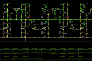
Here is an analog(!) dice I found on the net:

https://www.edn.com/a-fully-analog-electronic-dice/

  Are you sure? yes | no

Yann Guidon / YGDES wrote 02/10/2022 at 18:00 point

Doing a relay-based 3-stages Johnson counter was a snap. I'm struggling with the oscillator however, as I try a new approach that is gentler on the parts...

  Are you sure? yes | no

Ken Yap wrote 02/09/2022 at 23:07 point

Mine was a unremarkable design for the time, the mid-70s. I can't find any traces of my schematic (if I had one) so I'll just describe it briefly; not worthy of further elaboration.

I used a Garner oscillator (https://hackaday.io/page/5877) (sorry, no 555!) feeding a 7490 which drove a 7441 for a 1 of 6 output (I think the shop I did some casual work for threw out some sub-spec parts). The decoding was done by diodes feeding the 7 driver transistors, one for each pip. LEDs were expensive and too dim in those days and I used 12V bead bulbs, that's something you won't find these days. I cascaded two units. You pressed the button and the bulbs would cycle and flash. On release the dice would settle on a couple of patterns.

So only two TTL chips per die but quite a few diodes and transistors. Fairly high current draw due to the bulbs. Ah there must have been a 5V regulator for the TTL too.

  Are you sure? yes | no

Ken Yap wrote 02/10/2022 at 03:02 point

Actually I think there may have been less driver transistors since except for the centre pip the others are paired, so 4 transistors.

  Are you sure? yes | no

Tim wrote 02/10/2022 at 06:58 point

Wow, nice! So the one above from 1977 is already a "modern" LED version then. 7441 surely seems to be a very contemporary IC, i never fully understood the obsession with BCD in early microcomputers.

  Are you sure? yes | no

Ken Yap wrote 02/10/2022 at 07:04 point

7441 and the Soviet equivalent are now prized as they are BCD to nixie drivers.

  Are you sure? yes | no

Tim wrote 02/10/2022 at 07:06 point

Well indeed, BCD is very useful if you want to output to a nixie or 7 segment display.

  Are you sure? yes | no

Tim wrote 02/10/2022 at 10:46 point

The garner oscillator is really interesting. Nice way to save a few components.

  Are you sure? yes | no

Yann Guidon / YGDES wrote 02/09/2022 at 19:48 point

Where do I sign up ?

  Are you sure? yes | no

Tim wrote 02/09/2022 at 19:49 point

Just ask to join the project.


(well, I already invited you)

  Are you sure? yes | no

Similar Projects

Does this project spark your interest?

Become a member to follow this project and never miss any updates