Close
0%
0%

ModAir - Modular Aviation Instruments

Open Source Avionics for Microlights and other Non-Type-Certified Aircraft

Similar projects worth following
With electromechanical avionics becoming obsolete and expensive to repair, many analog gauge-type instrument panels are being replaced with an electronic flight instrument system (EFIS). Sensors and displays are cheap and readily available, yet commercial EFIS systems remain ludicrously expensive.

This project aims to create a low-cost EFIS system for non-type-certified aircraft such as:
- Ultralights
- Microlights
- Experimental aircraft
- Light sport aircraft

To support the various engine types, cockpit layouts, display sizes, sensors and required functionality, the system is built around a multi-master bus architecture. Measurements are periodically broadcast on the bus by sensor modules, while other modules monitor, control, display, log or forward this data.

Project Goals

The main goal of this project is to supply an open source infrastructure for avionics development. Each aircraft has different budgets and requirements for aviation instruments; trying to address them all with a single module is unrealistic. A modular approach splits functionality into reusable components. This makes it easier to maintain, replace faulty units, and upgrade by adding modules instead of replacing the entire system. An example is shown below:

Another advantage of the modular approach is that the project can be completed in stages, with nice-to-have features being added later. As a pilot, having access to real-time, reliable and relevant information greatly assists in the decision making process. Adding additional instruments thus becomes another way of making aviation safer for everyone sharing the airspace. With the centralised design of the original prototype, I needed to remove the electronics from the aircraft every time I wanted to add functionality. This resulted in not being able to fly while features were developed (which usually took longer than expected), or consequently not developing features because I wanted to fly.

The end goal is to have a library of modules that can be mixed and matched to suit different pilot and aircraft requirements. Examples of modules include:

Module Features Status
Rotax 582 Engine RPM, EGTs, H2O, fuel level, fuel flow, relay and open drain outputs prototype
3.0" Graphic LCD
Nelytech NT-G128641A 128x64 monochrome (Black on White) prototype
Navigation Waypoints, GPS, IMU, altitude, air speed design
Computer Interface Allows PCs, tablets, smart phones and smart watches to be used as multi-functional displays (MFD) planning
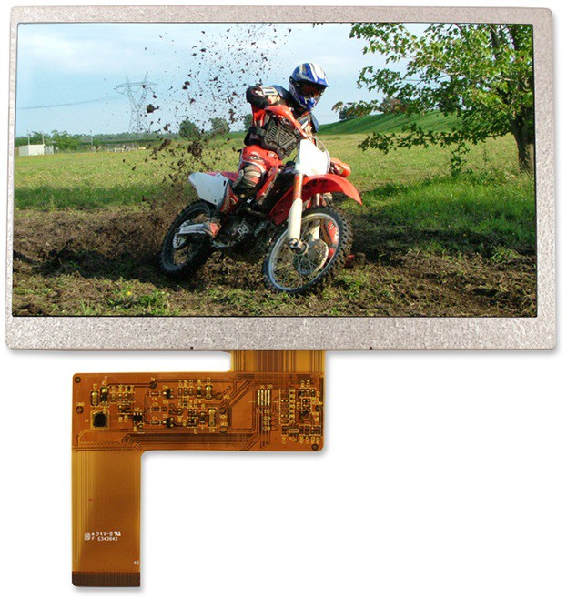
7" TFT LCD
Single board computer (RasPi / BB) with sunlight readable TFT LCD screen planning
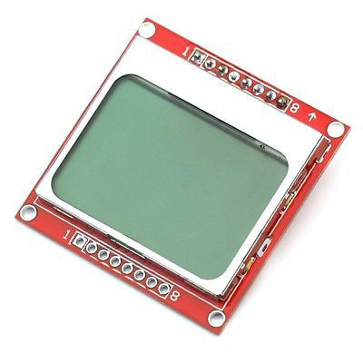
1.4" Graphic LCD Nokia5110 84x48 monochrome planning
Aircraft Interfaces Outputs for fuel pump, lights, flaps, trims, heater, gear, ... idea
VHF Transceiver Interface Remote interface for airband radio idea
Transponder Interface Remote interface for ATC transponders, altitude encoder for older Mode C types idea
Aircraft Intercom Annunciation, volumes, PAX idea
Situational Awareness SDR-based ADS-B receiver, air-band channel activity indicator idea
Air-to-air Communication Low-cost ISM-band position broadcasting (similar to ADS-B in and out) to keep track of other aircraft in your squadron idea
Black Box Logging to micro SD card idea
Power Alternator and battery management, voltage and current idea

Personal Goals and Current Priorities

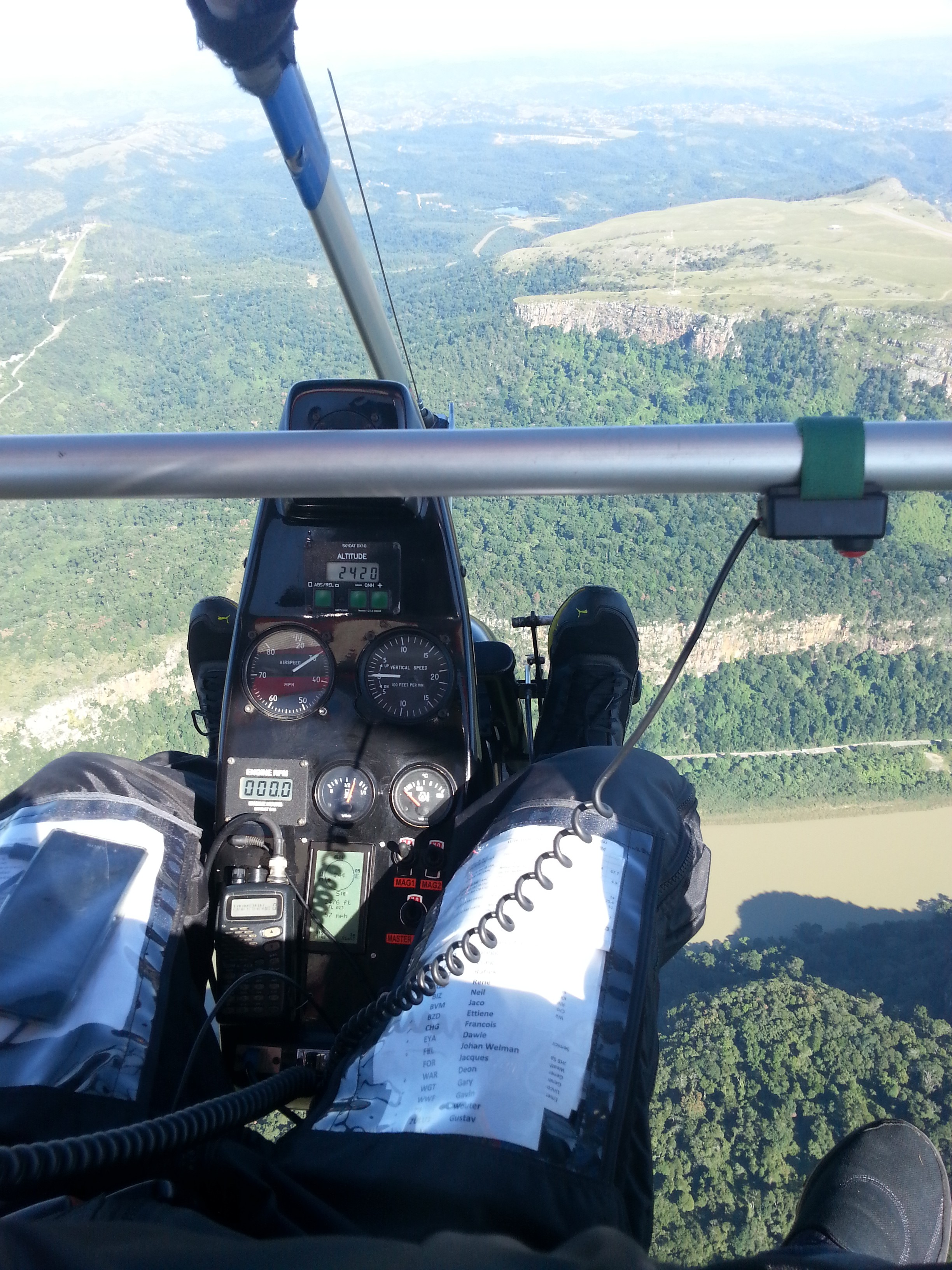
My main goal is to develop an advanced avionics system for my weight shift controlled (WSC) microlight trike (see background post). Being an open cockpit, my requirements might not always align with other pilots expectations. For example, touchscreen interfaces are almost impossible to use in-air (e.g. typing, zooming, panning); especially when fighting bumpy air and with thick gloves. Physical buttons, knobs and rotary encoders work quite well though. Depending on the angle of the sun, most TFT LCDs are challenging to read. Transflective STN LCD panels on the other hand, are easily readable in direct sunlight.


System Design

Requirements drive design. Read that again but slower. This project has three simple requirements:

  • Open source: design files and source code (for hardware, firmware and software) are hosted on GitHub under the GPLv3 license. This means that the contributions to this project may not be used in any closed source projects. Anyone is free to use the code for private and/or commercial use, but needs to publish any modifications under the same open source license.
  • Physically modular: modules (consisting of sensors, control outputs, interfaces, and/or displays) plug into a shared bus. Each module provides a specific set of features (also see overall feature wishlist) based on its attached peripherals. A module should be less than $100; if a set of peripherals exceeds this, the functionality should be split into smaller modules.
  • Modularity in terms of software: no firmware updates should be needed if a new module is added onto the bus. All the functionality related to the new module (which might be unknown at this point in time) needs to be self-contained. Having access to all other sensor readings on each module allows for some interesting data fusion and new parameters. For example, the module that measures the fuel level can also calculate the fuel endurance and range with the current tank, based on the ground speed and average fuel consumption.

On the display modules, this modularity is achieved by allowing the user to add widgets onto the screen, and linking them with sensor parameters as shown in the diagram below.
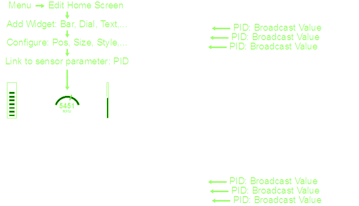
This approach applies to all display modules; whether small 2x16 character LCDs, monochrome graphical displays, Smart-phones, tablets or large colour TFT LCD screens. Widgets can be simple text, graphical items like gauges and bars, graphs that plot parameters (over time or against other parameters), attitude reference lines, 2D moving maps, or full 3D components such as synthetic vision (using topological maps and taking position and attitude sensor inputs).

For sensor modules, modularity is realized with a remote menu that can be accessed by a display module. This remote console can be used for configuration, alarm setup, viewing status, editing the value broadcast rate and any other options relating to the sensor.
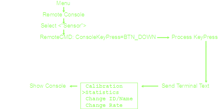
This also greatly simplifies the communication protocol. There is no need to define message types for calibration or any other sensor-specific data. Similarly, the display modules and rest of the system need no prior knowledge of how to handle custom user data. User inputs can be simple up/down/ok/... buttons, rotary encoder inputs, or any characters from a keyboard.

Read more »

  • Current Goal: new PCB order before Oct 2018

    Rene09/25/2018 at 07:37 0 comments

    Things have been a bit crazy at work for the past year, leaving me with limited time to spend on this project. I'm on leave for this week, and aim to send off the revised PCB order by 30 September 2018. This includes:

    • Design PCB for EastRising 3.4" LCD module
    • Design PCB for the Navigation module
    • Revise PCB for the Rotax 582 Engine Interface module
    • Revise PCB for the Monochrome LCD modules

  • Design Notes for Shielding and EMC issues

    Rene09/25/2018 at 07:02 1 comment

    The current avionic modules still cause interference on my VHF air-band radio. Whenever the power switch for the avionics is turned on, the radio intermittently shows the Rx light and plays channel noise. Turning the squelch all the way up reduces the issue to some extent. Unplugging the antenna on the radio stops the issue, leaving me to believe that I am dealing with radiated emissions from the avionics, rather than conducted emissions through the power supply.

    Below are some design notes for the next hardware revision to mitigate the EMC issues:

    • run the micro-controller at 80 MHz rather than 120 MHz (move the I/O and transistor switching noise further away from the air-band VHF frequencies)
    • PCB ground fill on both sides (traces become more like coplanar waveguides rather than radiating antenna elements)
    • PCB solder pads for an EMC cage (brass sheet bent into a box)
    • use in-line termination resistors for signals between integrated circuits on the same board
    • use low noise switching power supply modules

    The whip antenna position (in close proximity to the instrument pod) and limited ground plane (using the goose neck on the aluminium frame) are not ideal on my microlight trike. The aluminum frame structure and many stainless steel support wires make the antenna mounting challenging and distort the radiation pattern. I have not measured the VSWR, but expect quite a bad impedance match and significant reflections. If the next hardware revisions still cause interference issues, I will consider mounting a V or dipole antenna to the king post or the back of the keel.

  • Sunlight Readable LCD Selection

    Rene07/09/2017 at 12:37 0 comments

    I initially thought the 5.8" white-on-blue LCD module would be readable in sunlight, but having flown with it a few times now, the white pixels mostly vanish under direct sunlight (even with the blue back-light set to maximum brightness). For sunlight readable screens:

    • Any monochrome LCD should be of FSTN Positive type, preferably with black pixels on a white/grey background.
    • Any color TFT LCD screen needs to have an ultra-bright back-light with an absolute minimum brightness of 700 nits (1 nit is equivalent to 1 cd/m2).

    For sunlight readable color TFT screens, the transflective variants (which transmit light when the back-light is turned on and otherwise reflect light) are extremely expensive and difficult to procure. TFT modules with ultra-bright back-lights are easier to procure but typically cost a few hundred dollars. After multiple days of googling, browsing catalogs and comparing screens, I've selected the following options, which should suit most cockpits and budgets:

    1. Nokia 5110 LCD Module

    1.4 inch (29 x 19 mm active area) 84x48 pixel monochrome, (less than $2 on AliExpress).

    These modules use the PCD8544 controller with a serial interface to the microcontroller. Their small size makes them ideal to fill a standard 2.25" instrument panel hole. One could have multiple of these in the cockpit, each with enough space to show a graphical widget, 1 to 2 large font parameters, or 6 to 7 small font parameters.

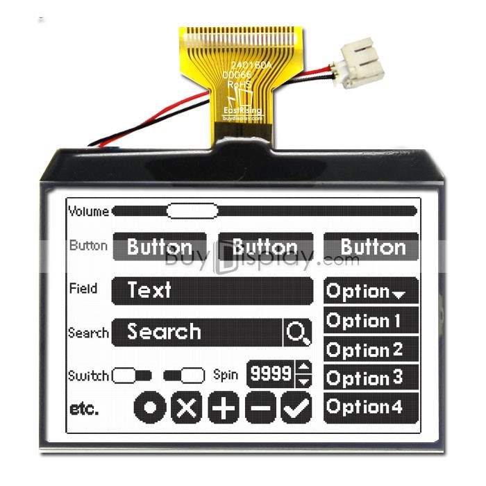
    2. EastRising ERC240160FS-1 Module

    3.4 inch (72 x 48 mm active area) 240x160 pixel monochrome, (around $11 from BuyDisplay).

    The solderable FPC ribbon interface supports both 8-bit parallel as well as serial communication to the ST7586 controller. The screen size, pixel density and price make this module quite attractive for most use cases.

    3. Newhaven NHD-7.0-800480EF-ASXN# Screen

    7 inch (154 x 86 mm active area) 800x480 pixel color, 1000 cd/m2, (around $80 from Newhaven).

    This is by far the cheapest sunlight readable TFT screen that I found in this size category. It uses a 24-bit parallel RGB interface, which is supported by most single board computers (e.g. the RaspPi Display Parallel Interface [DPI] as a multiplexed function on the GPIO pins). Alternatively an external controller can be used to drive it via HDMI. Touchscreen versions are also available, trading off a bit of brightness.

  • Lesson Learnt: Shielding

    Rene05/23/2017 at 19:42 0 comments

    Last weekend I got the firmware to a state where it could be used in the aircraft and installed it all into the pod... Not very pretty, but it'll do for now.

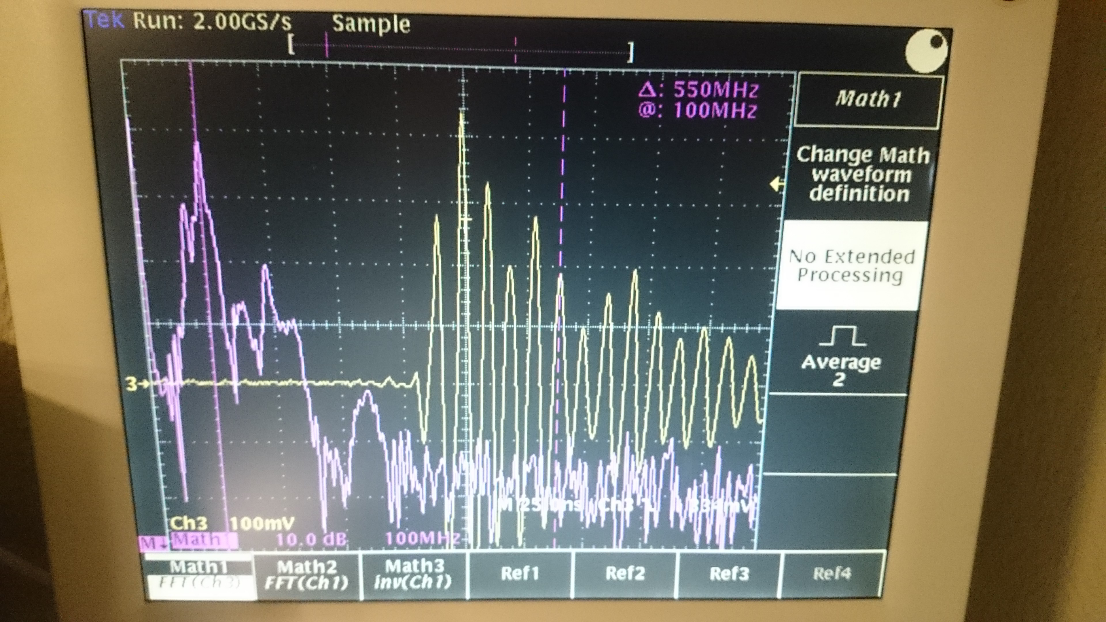
    During my pre-flight checks I noticed that the radio was picking up interference (the SQL had to be set all the way up to suppress it); Upon closer inspection with the oscilloscope I noticed that the switched mode power supplies were ringing around 100 MHz during both the rising and falling edges... Additionally the Microchip PIC is set to run at 119.763 MHz. The capture below was taken with a floating probe around 5-10cm away from the SMPS.

    Re-wiring the electronics with shielded cables (and connecting only ONE side of the shield to ground) fixed the issue. It's clear that each of the modules as well as all interface cables should be properly shielded to suppress their emissions, and shield them from the VHF radio and transponder RF!

  • Other CAN-bus Aviation Protocols

    Rene04/22/2017 at 12:29 1 comment

    This section tracks and compares various aviation-specific CAN-bus protocols. Being open source, support for these protocol can always be added at a later stage if required.

    Read more »

  • Other Open Source Avionics

    Rene04/22/2017 at 11:56 0 comments

    This section tracks other open source avionics projects, for the purpose of collaboration and design reuse. Please let me know if you know of any other initiatives.

    Read more »

  • System Bus Decision

    Rene04/22/2017 at 10:21 0 comments

    The entire design is built around a shared bus, into which multiple modules, interfaces and screens are plugged in. With various sensors asynchronously producing data, a one-to-many bus that supports message broadcasting is required. This leaves us with some options...

    Read more »

  • Feature Wishlist

    Rene04/20/2017 at 12:53 0 comments

    I find it useful to envision as many future requirements as I can think of. That way the architecture can be designed with future upgrades in mind, even if these features are never actually implemented.

    Read more »

  • Background

    Rene04/20/2017 at 12:49 0 comments

    I have always dreamed of flying and was fortunate enough to be able to complete my recreational pilot license a few years ago. South Africa is an amazing country to explore by air, especially in an open cockpit of a Weight Shift Controlled (WSC) trike!

    Read more »

  • First Batch: Assembled Modules

    Rene02/05/2017 at 13:21 0 comments

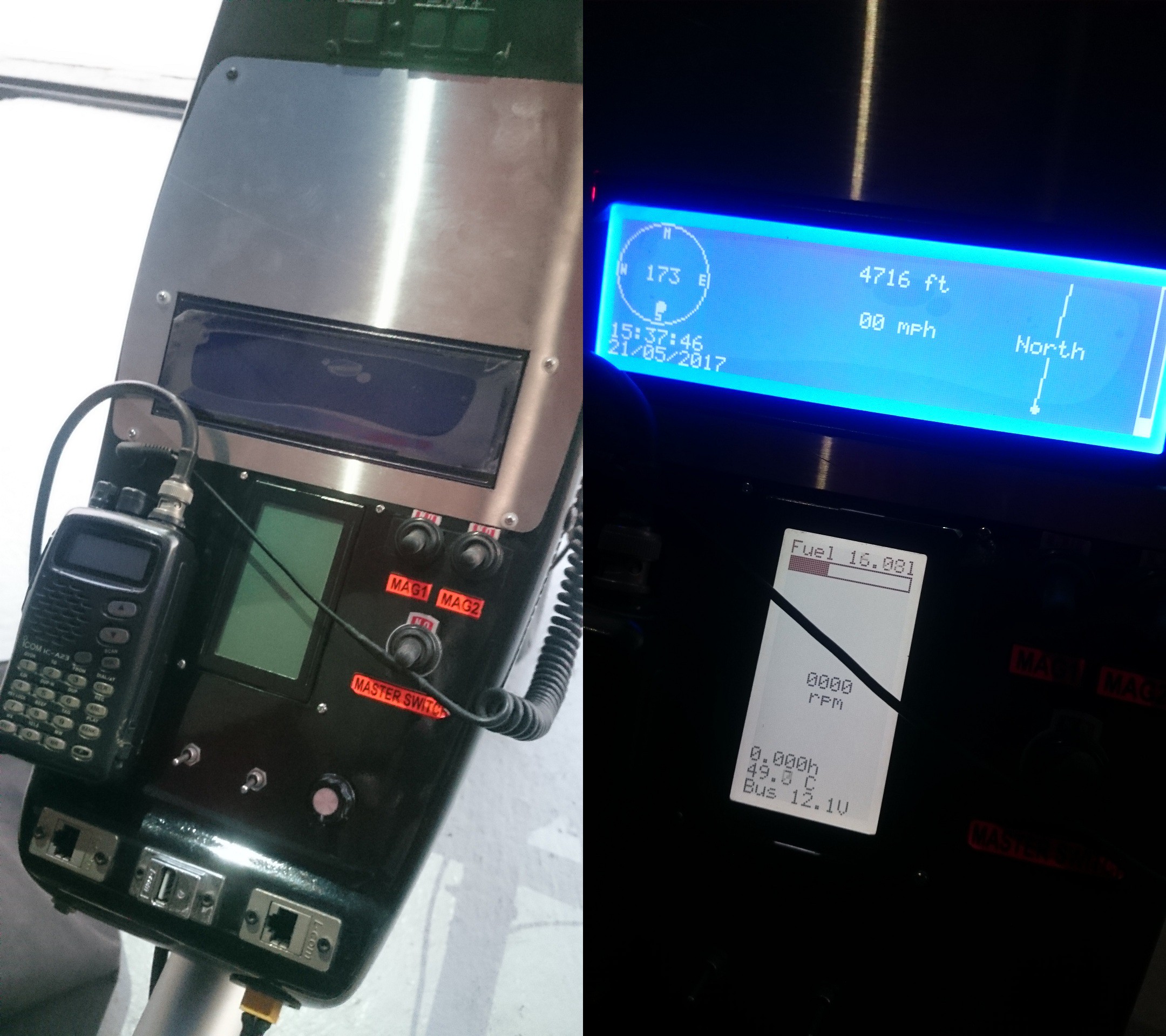
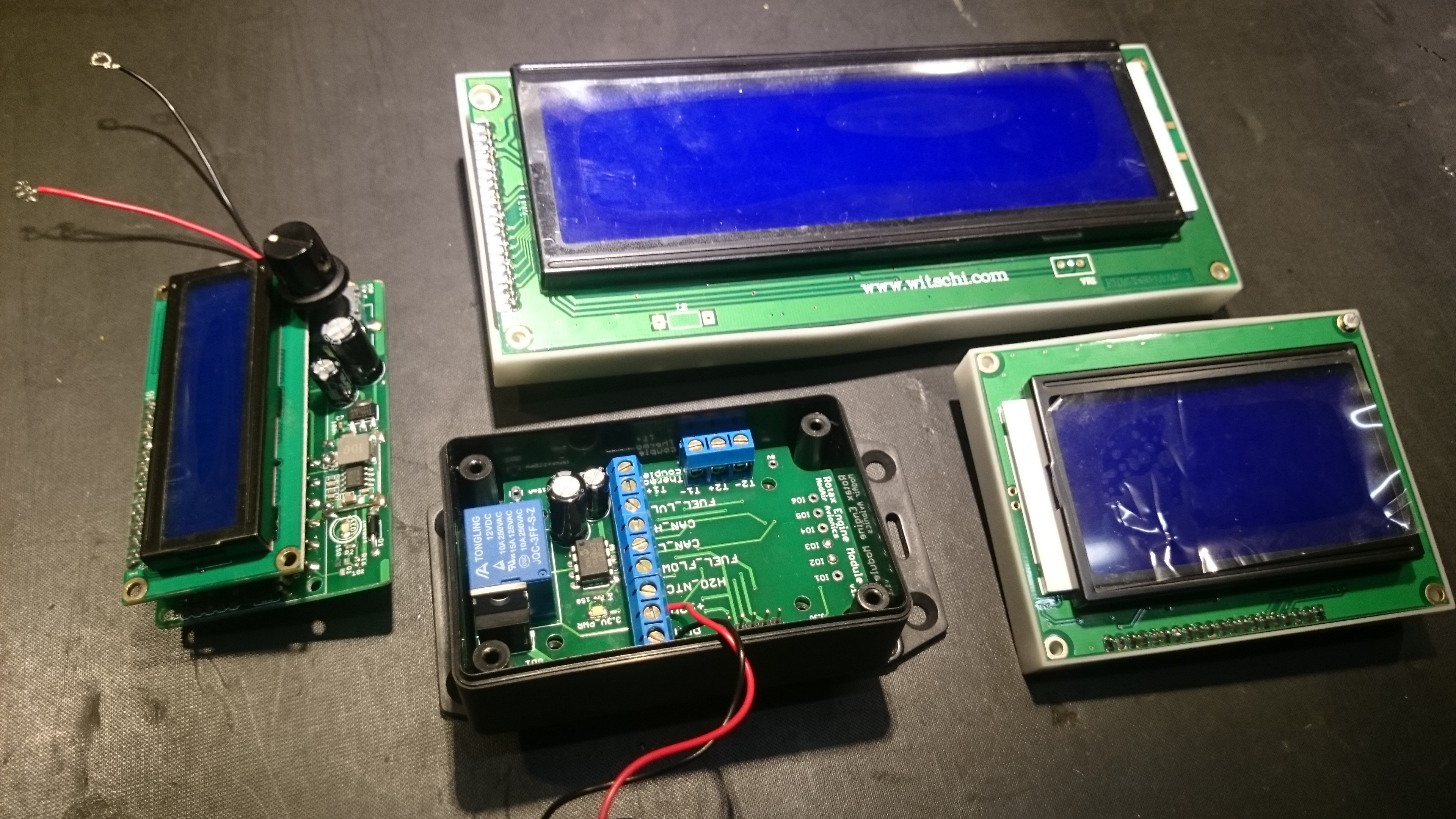
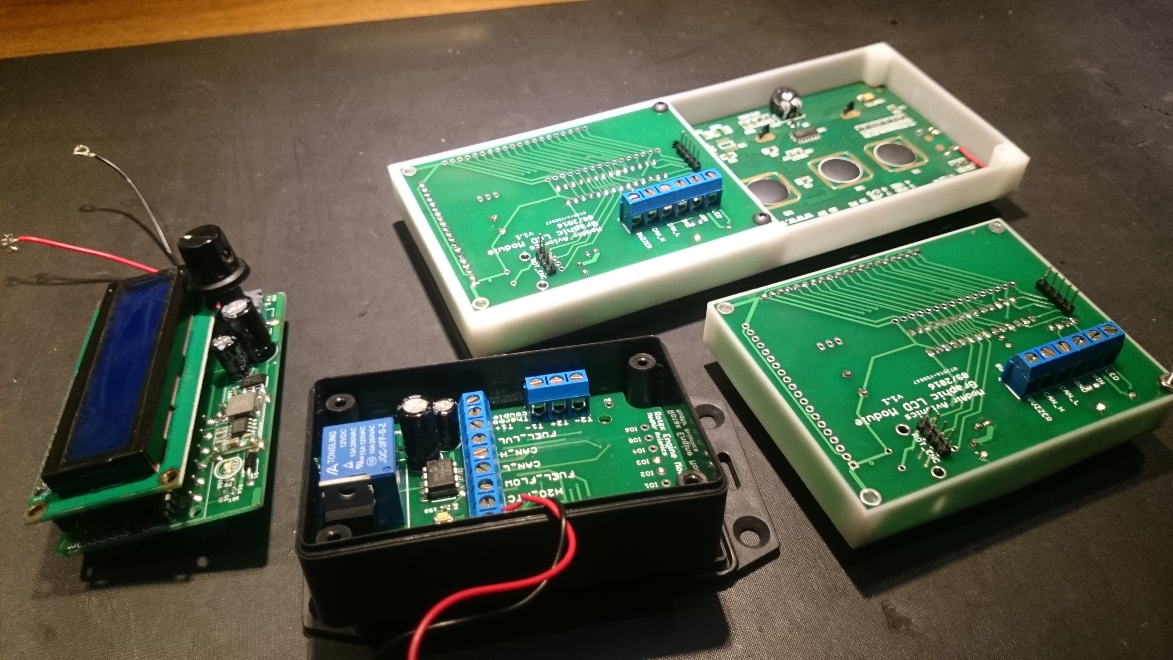
    For the first manufacturing batch, I decided to focus on the bare essentials: LCD screen module and engine monitoring module. The screen module PCB was designed to fit some of the more common graphic and character LCDs from China. Here are some pictures after soldering and assembly.

View all 10 project logs

Enjoy this project?

Share

Discussions

valle wrote 05/04/2019 at 13:51 point

Hey Rene,

I just joined hackaday for this project. I was just tinkering up some similar thoughts as well. I'm a automotive EE by trade (HW, SW) and student pilot by heart. Would love to take part in this because I strongly believe the big age of aviation is yet to come! Anyone excited to go electric?

I'm interested in data logging and analysis ... an open-standard common CAN bus for all systems is just what a plane needs nowadays.

  Are you sure? yes | no

radiusmike wrote 04/07/2017 at 03:57 point

Great project.  I am a pilot and have owned aircraft, so am very familiar with this technology and think your approach makes good sense, I am building a set of instruments for my Honda Pilot ATV starting with EGT and CHT.  Am willing to help out here and there when/where I can.  

  Are you sure? yes | no

Rene wrote 04/07/2017 at 07:20 point

Thanks! If your EGT/CHT thermocouples are type-K, I found the MAX6675 very useful. Schematics and firmware are on Github. Good luck with your ATV and thanks for your offer to help

  Are you sure? yes | no

William wrote 04/05/2017 at 22:39 point

Hello Rene! An excellent project indeed! I would like to help with your project. I have little time, these days, but I did start an open-spec project a few years ago to help solve many module-related obstacles we face. It is largely built around aviation/industrial connectors. It has the protocols (CAN, I2C, SPI)  & topology you require. The project is listed on my profile. I'm eager to learn more about your project and help in any way I can (perhaps, even, with some long-distance prototype collaboration). All the best...

  Are you sure? yes | no

Rene wrote 04/06/2017 at 19:58 point

I quite like your open-spec project... Will spend some time reading :) Thanks for your support and offer to help

  Are you sure? yes | no

wintercabin2007 wrote 04/05/2017 at 22:20 point

I have a Lancair 360 that I can use to test any of your systems.  There are existing CHT, EGT and Fuel flow sensors and I have a variety of parts (Raspberry etc) that could be incorporated.  I did do some experimenting with National Instruments stuff (accelerometers etc) but things have changed substantially over the past 4-5 years. I also found trying to source sunlight readable displays a problem , hopefully you have had better luck.   Let me know if there is anything I can do to help including a financial contribution.  

  Are you sure? yes | no

Rene wrote 04/06/2017 at 19:55 point

Thank you for your willingness to help. I really appreciate it; will keep you updated!

  Are you sure? yes | no

samern wrote 04/02/2017 at 11:51 point

Absolutely.  I am a bit far from first flight in my Corvair Cruiser or Zentih, but I can code and I certainly can build and most defintely test.

  Are you sure? yes | no

samern wrote 03/31/2017 at 21:57 point

As a pilot and Experimental Aircraft builder I would love to help in any way I can.  I am willing to also build variants and take them up when I fly and report on how well they work or respond.  I love the idea of modular instruments given the crazy cost and maintenance grief of MFDs, PFDs and EFIS systems these days.  You just know Synthetic Vision is going to have to be part of this, right?  Touchscreen and RasPi goodness!

  Are you sure? yes | no

Rene wrote 04/02/2017 at 11:42 point

Excellent! Thank you for your offer to help and feedback... YES!!! Just thinking about all the options with Synthetic Vision is exciting: terrain, airspaces, approaches, obstacle avoidance, etc... For the next few months the focus for me will be more on the sensors, hardware and firmware, but I'm really looking forward to the software side of things too :) You are more than welcome to get started on that so long. I would also appreciate any design inputs and suggestions. Thanks again for your willingness to help

  Are you sure? yes | no

Similar Projects

Does this project spark your interest?

Become a member to follow this project and never miss any updates