Close
0%
0%

EEEmu SPI

25MHz 1.8-5V SPI EEPROM/Flash Emulator

Similar projects worth following
The EEEmu SPI emulates any Serial Peripheral Interface Bus EEPROM or Flash memory chipsets up to an interface speed of 25MHz. It also supports any supply and interface voltage between 1.8 to 5 Volts and can be configured to support even the largest of memory sizes.

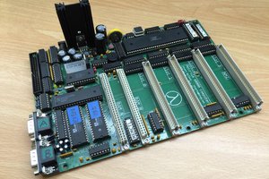
The world's landfills are littered with old PC motherboards that have failed due to bad flashing, malware or rm /sys/firmware/efi/efivars/*. What if you could recover these boards easily or prevent it from happening all together?

The EEEmu SPI will allow you to do all of this and more. EEEmu SPI can:

  • Create a truly crash-free BIOS solution for your PC motherboard.
  • Recover bricked PC motherboards.
  • Secure your BIOS from accidental or malicious modification while still allowing easy BIOS updates.
  • Check if changes are made to your BIOS by storing EEPROM writes in a diff file (if write enabled) and also write protect sections of ROM.
  • Swap out different EEPROM and Flash ROM files quickly and easily via a USB mass storage interface.
  • Retrofit worn out or end-of-life chipsets on older hardware. SLC NAND for example, is prone to shortages, price fluctuations, and EOL notices.
  • Provide an easy development and deployment environment for custom PC BIOS modification.
  • Develop and debug embedded projects, without worrying about exhausting write cycles.
  • Also emulate Flash/FeRAM/MRAM SPI hardware.
  • Be connected to embedded or IoT platforms to allow them to perform easy datalogging and data storage functions.
  • Be used as an SPI sniffing and logging device.
  • Create custom SPI slave hardware.
  • Anything else you can imagine that requires a versatile high speed serial memory interface.

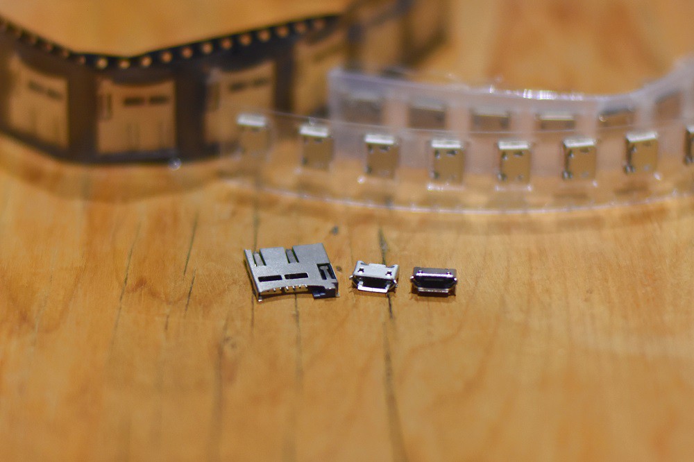
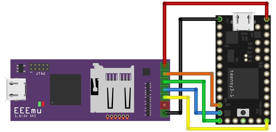
EEEmu SPI is easy to use as a simple drop in replacement for existing SPI EEPROM. It allows you to quickly and easily configure and load new EEPROM image files using a USB mass storage interface, to onboard storage. Deep configuration options allow you to tweak the operation easily to support any brand or sized EEPROM.

EEEmu SPI also provides additional 3.3V GPIO/I2C pins to allow you to hack the device to your heart's content.

Level conversion supports open drain (pull-up) or active modes. Dual power supplies allow you to power it from the USB or SPI interface (even at the same time).

EEEmu's software is also completely open source. It supports reprogramming via USB, so you can easily tweak the code to suit your application.

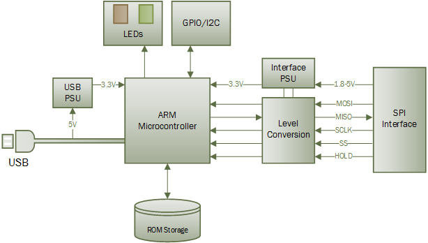
After Step 1, collect underpants, and the emulation code in the firmware is finalised, an initial run of these boards will be available for sale on tindie.com for developers and hobbyists. It is hoped that the community adds additional functionality to the open source firmware to create a robust and versatile EEPROM emulation platform.

All EEEmu code, documentation and design on these project pages are licensed under the GNU General Public License (GPL) unless otherwise stated.

  • 1 × ATSAM4S Microprocessors, Microcontrollers, DSPs / ARM, RISC-Based Microcontrollers
  • 1 × MicroSD Socket
  • 1 × TPS63031DSK Power Management ICs / Switching Regulators and Controllers
  • 1 × TPS73233DBVT Power Management ICs / Linear Voltage Regulators and LDOs
  • 4 × SN74LV1T34DCKR Logic ICs / Buffers, Drivers, Transceivers

View all 10 components

  • Fritzing Part

    Blecky06/12/2017 at 07:56 0 comments

    I have added a basic Fritzing part to the EEEmu repository - https://github.com/EEEmu/Assets/tree/master/Fritzing

  • Rev 2 Boards Arrived

    Blecky06/11/2017 at 10:12 0 comments

    The Rev.02 EEEmu boards have arrived. The boards are looking pretty full, but they are the same size (51.5x20mm) and still have single sided component placement to make manufacturing easier.

    The Rev.02 boards have quite a few changes:

    • Extra GPIO break out pins.
    • High-Z control for SPI outputs.
    • Modified diameter for programming pin holes.
    • New footprint for 4UCON SD card slot.
    • USB voltage monitoring for smarter sleep states and operation.
    • Additional resistors to comply with JTAG spec.
    • Placement fixes for parts.
    • Better silkscreen text sizes.

    These should be made up shortly. The only change before production for this board is to swap the USB footprint for the new connectors.

  • Testing Connectors

    Blecky06/11/2017 at 08:23 0 comments

    I've been recently looking for a cheap supply of USB and SD card mounts/connectors to bring the costs of the board down (some SD card mounts from other manufacturers are a few dollars each even in large quantities). I found what seems to be a decent supplier of all different connector styles from 4UCON, however they took a while to send samples, because they normally do business in larger quantities. They eventually shipped and arrived in the end.

    From left to right the part numbers are 15882, 20696 and 11071.

    The only downside if that they don't have much in the way of datasheets, only that we can assume the plastic insulator is a Liquid Crystal Polymer (LCP) with a UL94V-0 flammability rating (with the 11071 connector being LCP with glass fiber).

    So what sort of characteristics or tolerances do these connectors have under reflow conditions?

    Read more »

  • EEEmus Can Run Fast

    Blecky04/28/2017 at 19:15 0 comments

    One of the main design constraints behind the EEEmu SPI is that it has the ability to emulate some of the faster Flash SPI chipset specifications to allow for BIOS Flash ROM emulation.

    Enter the SAM4S. These 120MHz ARM based devices are capable of running with various programmable delays for flexible SPI compatibility and an SPI slave frequency of 25MHz. This speed is a reasonable compromise on price and performance and covers most use cases for embedded design.

    These microcontrollers are no slouch when it comes to performing operations either. However this is not the only hurdle when designing such a system. The choice to allow users to store the ROM information on an SD card also brings about significant design considerations. SD cards by nature are a sector addressable device and cannot be read byte by byte like traditional EEPROM. So how do you get low latency performance out of a setup like this?

    Firstly you must consider that the speed of the card plays a significant factor. So choosing the right card is crucial to getting decent performance. For testing, a card with a read write speed of 95MB/s has been chosen. This speed of card has been selected to allow the lowest reasonable latency while operating at higher SPI bus speeds. Secondly, we don't want to tie the CPU up with performing SPI and SD transactions. The good thing is these devices have their own SPI and HSMCI peripherals which do most of the work and provide data as registers when available. Once the hardware side of things is sorted, you then move onto software.

    Initially through testing a sequential SPI read transaction from a ROM file, the system would take around 320us to read the next sector once the SPI interrupt requests byte information on the sector boundary (every 512 bytes). This was by no means good enough. The EEEmu sources use the Atmel ASF libraries to operate the SD Card, SPI interface and FAT(32) filesystem.

    These libraries are "basic" and designed to run the demonstration application. A few tweaks are required to get them running the way you like. The first main issue with these libraries is that they will first do a check to see if the SD card is inserted. This first check has a massive timeout delay of a second to make sure the insertion has "debounced". Subsequent checks don't have this debounce delay however. So to speed things up on startup, this delay is removed on the first check only and if the card is removed while running, the check will be performed again. It turns out they also had several nested redundant checks (4) to see if the SD card was still inserted and operational on every byte read, even if it was reading from the FAT library’s sector buffer.

    Once fixed, the performance was much, much better, but still not good enough for 25MHz. To operate a byte addressable ROM format, you must tell these FAT libraries to perform an f_lseek operation to access the byte you are looking for. Unfortunately this seeking is a little slow, even if it’s from the sector buffer. So you have to put statefulness procedures in there to check if the next byte to read is the byte being requested and to ignore the use of f_lseek (note that on each byte read operation, the byte pointer moves to the next byte for the next read).

    After all of this, we bring the read latency on a sector boundary down to around 10us or less (with no perceivable latency on a next byte read). While a whole lot faster than 320us, it can still be much better (for example for loading BIOS program data), considering we want operate up to an SPI data rate of 25MHz.

    Enter the Buffer

    One thing these embedded FAT libraries lack is decent buffering. This is due to the fact they are designed to operate within small memory restrictions and multitasking is difficult on smaller microcontrollers. Well the SAM4S has a fair bit of memory, so why not use it?

    Well we don’t want to use it all because we will want a large buffer for optimal write operations and RTOS task stacks, so let’s get smart...

    Read more »

  • The EEEmu Lives

    Blecky04/24/2017 at 13:33 0 comments

    As a first post, I just wanted to give an update on where the EEEmu SPI development currently is.

    I started designing this project around the end of February this year after I became frustrated with having to manually re-flash 20 out of warranty server BIOSes. These machines needed updating to work with some specific PCI-e hardware, and unfortunately they would brick after a software based flash. Pulling the ROM, manually flashing, then re-inserting worked, so it wasn't a firmware issue. Since the manufacturer was less than helpful, other than to suggest to RMA them, I wondered how I could provide a quick, easy and software-less update method to prevent this issue from ever occurring.

    Development of the first prototype board then started in March. Things have progressed rapidly since then and I hope to have everything on the prototype fully operational by mid May. From there, a new revision of the hardware should be finished and I will start producing the first batches of boards after testing.

    This project has been designed to be produced easily on a smaller scale. I now also have the capability to build small batches myself (about 100/day). The plan is to have these boards available on Tindie as soon as they are ready.

    So onto the current status. All the code for the USB mass storage, SD card, configuration files and SPI is currently operational. The emulation code is still being worked on as I want it to be as flexible and easy to use as possible. Code will be made available once this and the firmware bootloader is finalised.

    The hardware on the prototype is also fully working. The dual power supplies work under all conditions without fault. The level conversion works as expected with different voltages (1.8-5V) and the SPI works well at 25MHz:

    Testing SPI reads from a ROM file stored on the SD card with a Teensy 3.2 @ 25MHz

    Connecting the Teensy to the EEEmu SPI is easy:

    Everything is coming together quite nicely without too many issues. I did have a minor one which "bricks" the ATSAM4S2B MCU. When entering a certain sleep state, the system controller switches off the internal 1.2V regulator, which then powers off the ARM core and prevents it from being programmed afterwards. There is a flash erase pin that you can bring high on startup for 10 seconds to erase the flash, but this is a frustrating design decision made by Atmel/Microchip.

    That's it for the moment. Stay tuned for more updates!

View all 5 project logs

Enjoy this project?

Share

Discussions

Richard Aplin wrote 12/20/2021 at 00:58 point

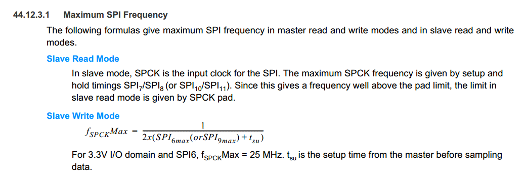
I don't get how this is actually going to work... I mean to emulate regular SPI flash you need to reply with the first byte of data on the next SPI clock after the host has sent the address.... and you don't control the clock. Hence, you have a fiercely low latency requirement; at 25mhz SPI clock that means you have to have fetched any random byte the host specifies from your storage medium within 40ns. It's actually worse than that, because of latency in your MCU's SPI slave hardware etc.  Using an SD card is never ever ever going to meet this requirement..    so..??   I assume this is why the project was canned?

  Are you sure? yes | no

NobodyYouKnow wrote 06/23/2020 at 14:05 point

I'll second that question about the missing repository. I'll be sad to see it has been removed.

  Are you sure? yes | no

Big Jake wrote 06/22/2020 at 07:02 point

What happened to the repository?

  Are you sure? yes | no

lee steensland wrote 12/08/2018 at 04:00 point

is this project still active? I can’t find the hardware on tinder for sale. I could use about a dozen of these.

  Are you sure? yes | no

Brian Winkler wrote 06/04/2018 at 07:16 point

I made an account just to like this project. Keep up the good work!

  Are you sure? yes | no

Christian W. wrote 07/19/2017 at 20:48 point

Blecky: Excellent implementation. Congratulations.

  Are you sure? yes | no

DD wrote 07/18/2017 at 14:36 point

Hihi, 
I made a version of the Arduino core for the SAM4S4A a while back, ( it snot in Arduino 1.5x format so one can't use it via boards manager yet ) but if you shove the files in  arduino/hardware ( windows ) then you should be able to compile for it, or use this as a starting point if you are ever interested in "Arduino IDE and API " for the EEEMu

my port was partly based on the SAM3S used in Flutter, 

https://github.com/Daniel-dk/motionbow

  Are you sure? yes | no

Blecky wrote 07/19/2017 at 01:21 point

Hi DD, this is definitely something I will look into at a later stage for other people to dev on the board. Cheers!

  Are you sure? yes | no

Electronic Eel wrote 07/17/2017 at 21:21 point

Did you consider that a lot of current PC motherboards use Quad SPI to connect to their BIOS flash ic? I'm missing the WP and Hold lines usually used for that. Also all 4 data lines are bidirectional for Quad SPI, so you can't use unidirectional level shifters.

  Are you sure? yes | no

Blecky wrote 07/18/2017 at 10:58 point

For most newer boards I'm considering a "pro" version of this board that would support things like that. The speed that this supports probably wouldn't work with much newer boards as well so the pro version would support higher speeds. But this is a great way to get the emulation code underway and be useful for developers and older hardware.

  Are you sure? yes | no

oshpark wrote 04/19/2017 at 17:26 point

Is the source code for the ARM firmware available?  It looks like the repo is empty: https://github.com/EEEmu/EEEmu-SPI

  Are you sure? yes | no

Blecky wrote 04/19/2017 at 23:34 point

It will be once I finish up the emulation code. I was mostly just getting everything in place a day ago for the hackaday prize conditions, so it's a little pre-emptive.

  Are you sure? yes | no

Yann Guidon / YGDES wrote 04/19/2017 at 08:56 point

I should get one and see how it behaves with #SPI Flasher :-D

  Are you sure? yes | no

Blecky wrote 04/19/2017 at 09:09 point

I hope to have this available for purchase on tindie in the not too distant future (hopefully end of May). I'm still working out a few things with the emulation code (USB/SD/configuration all currently work) as well as the end user flashing to make it reliable for people to make code changes. I will be looking for a few people to test it out first too if you are interested.

  Are you sure? yes | no

Yann Guidon / YGDES wrote 04/19/2017 at 09:28 point

interesting :-)

i trust you on the HW side but what about the user SW side ?

  Are you sure? yes | no

Blecky wrote 04/19/2017 at 09:39 point

There isn't too much from the user side as I tried to design it as a standalone device (once configured). All configuration is done through a config file that is placed on the SD card. The only thing I really need to do is make a generator that creates configs for different EEPROM devices. I plan to support everything that is on the flashrom site first as it's an easy go-to list, then there'll be more to come later. I'll have a way for users to submit working configs too. As for debugging/sniffing, there's two options, the first is to just dump SPI transactions to SD storage, the second will allow you to see these as debug statements over USB. As to how this is visualised, I'll look into this down the track as it can be a massive amount of data for the eyes to ingest.

  Are you sure? yes | no

Prodigity wrote 07/18/2017 at 10:13 point

Cool project, I could use one of these :)

As to how to visually present the SPI transactions; perhaps wireshark would be suitable?
https://www.wireshark.org/docs/wsdg_html_chunked/ChDissectAdd.html

  Are you sure? yes | no

Blecky wrote 07/18/2017 at 10:59 point

I will totally consider that @Prodigity!

  Are you sure? yes | no

Similar Projects

Does this project spark your interest?

Become a member to follow this project and never miss any updates