Close
0%
0%

L-Star: Software-Defined 6502 Computer

Replicate an Apple-1. Or an OSI Challenger. Or something else.
Design your own 6502 computer by programming it.

Similar projects worth following
Building your own computer and knowing all the details of how it works, is (arguably) a lost art.

This project lets you build a 6502 computer that helps you not just understand, but also control important details of how it works.

L-Star connects a Western Design Center W65C02 to a Parallax Propeller. The Propeller monitors the address bus and data bus, and emulates memory and I/O devices.

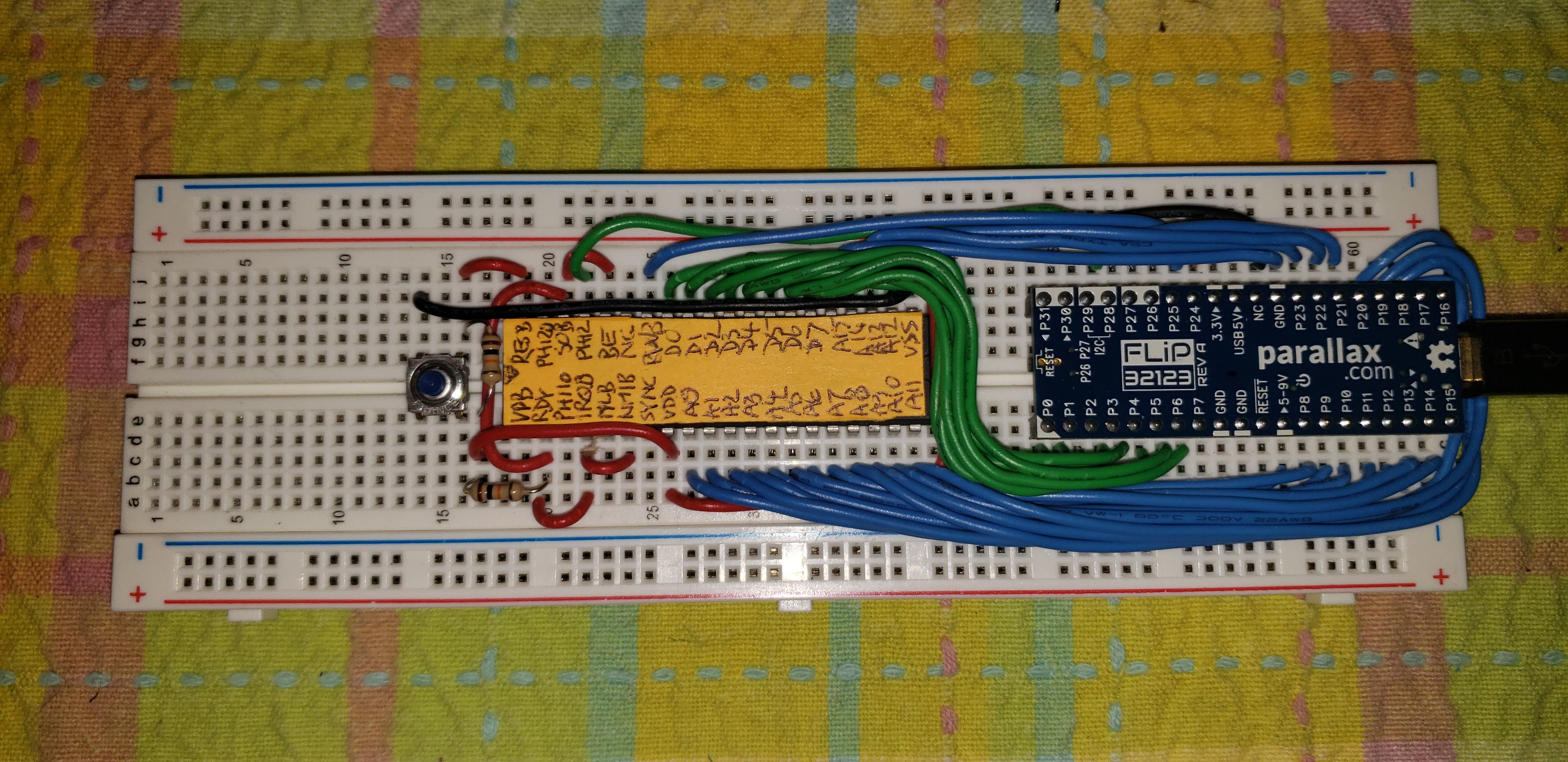
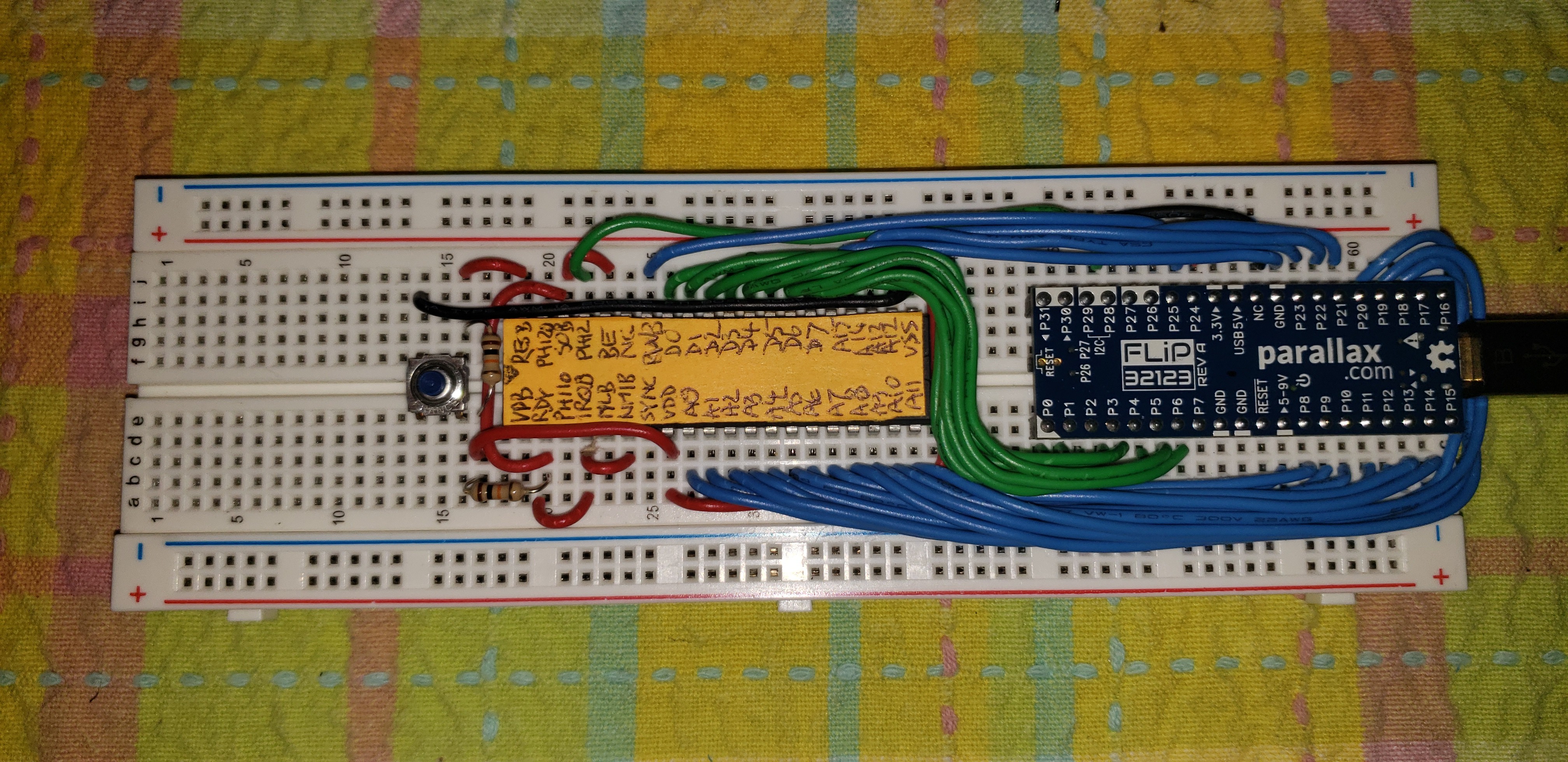
The simplest version of L-Star can be built on a breadboard (see the "instructions" section).

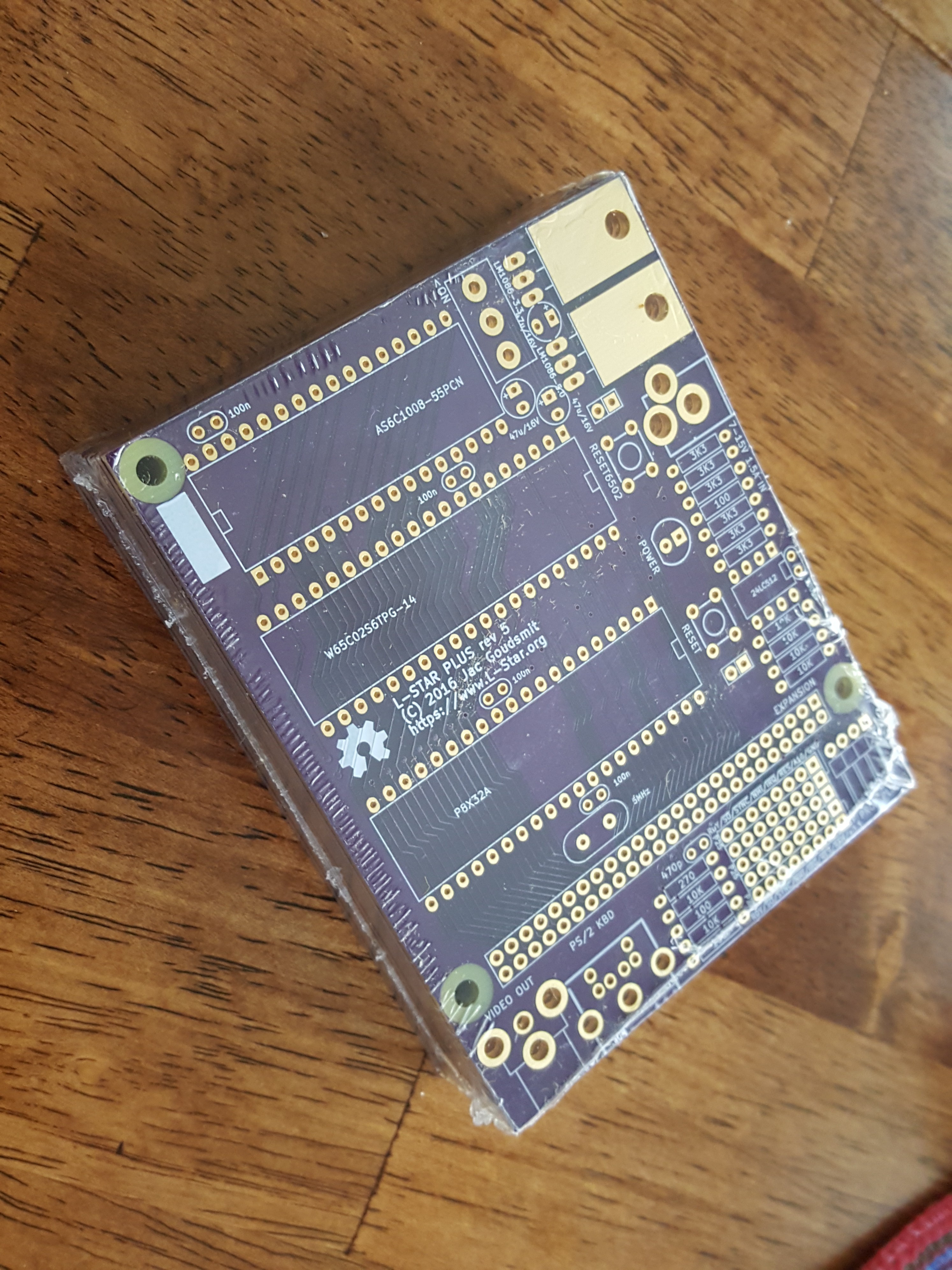
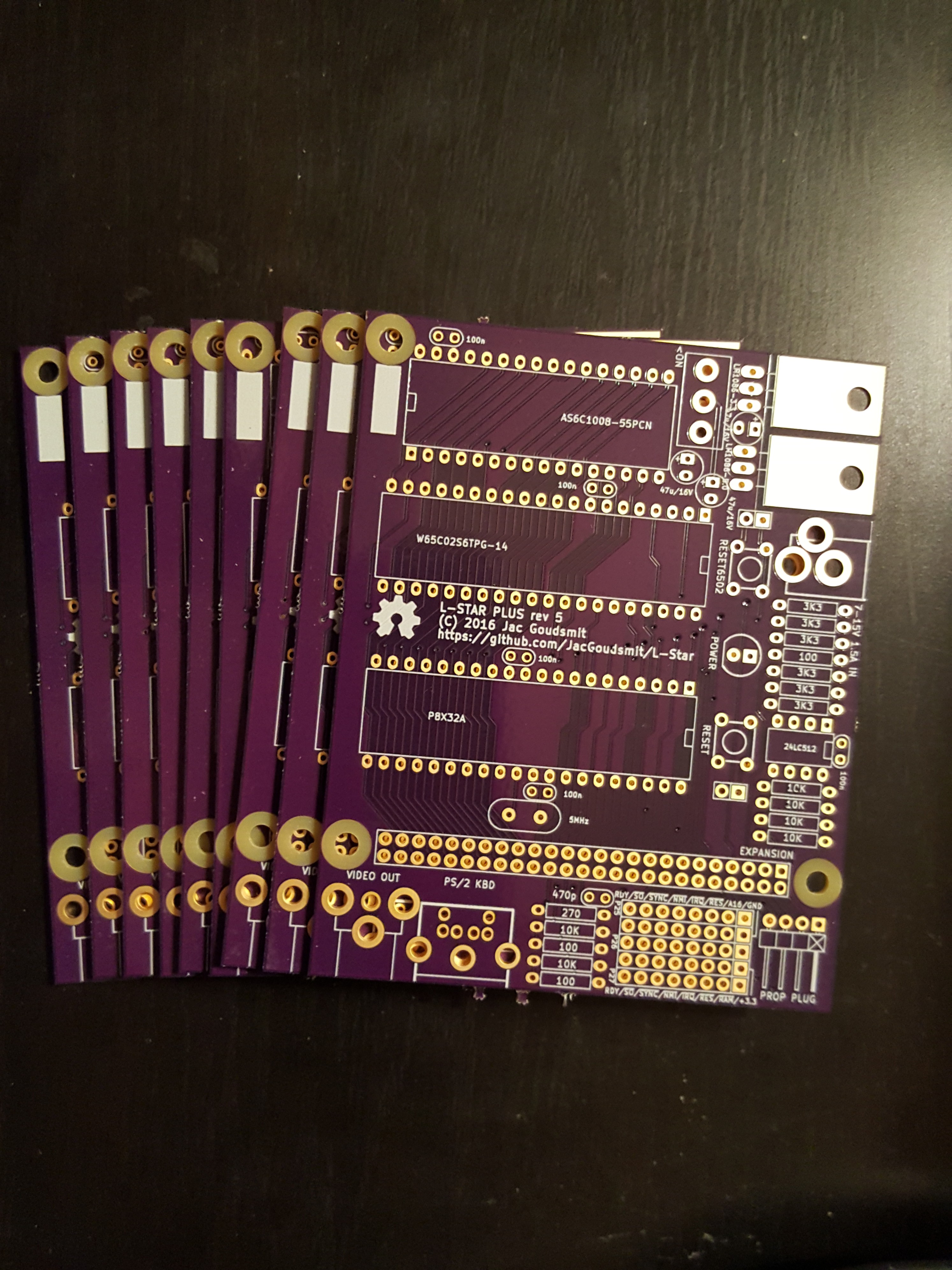
L-Star Plus is a kit version of the project with some extra features: it adds a RAM chip, power supply circuitry, and an expansion port.

I no longer work on this project and I don't make the kit available for sale anymore, however there are links to OSHPark and Mouser if you want to buy the PCB and the parts. Go to l-star.org for more information if you own the kit.

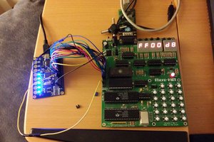
The L-Star project is an open-source single-board computer design that uses a Propeller microcontroller to control a 65C02 processor. You can use it to emulate early 6502-based computers such as the Apple-1 or the OSI Challenger, or you can invent your own 6502 computer.
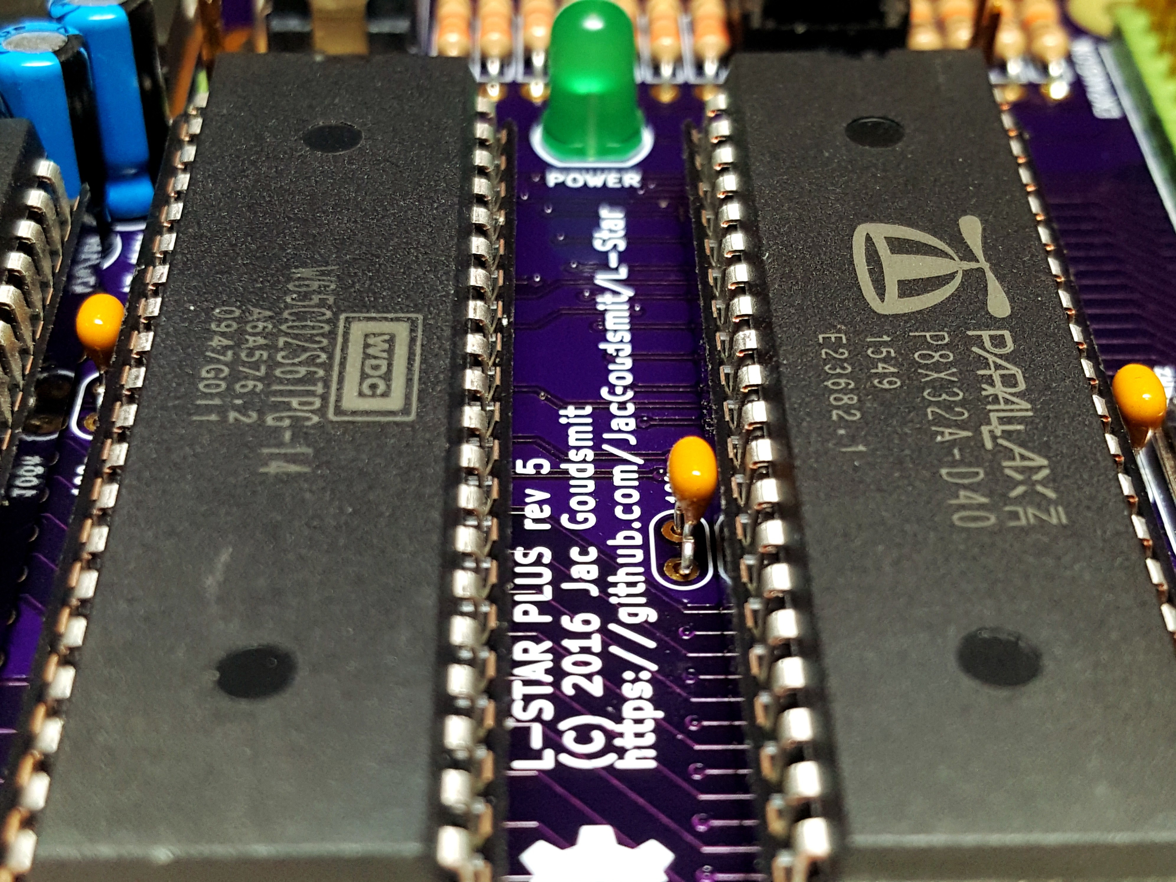
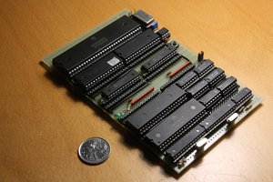
All the parts that are needed to put an L-Star together are available in through-hole packages, so you can build it on a breadboard, or on a Propeller proto board. Or you can order a kit on Tindie (click on the Tindie link on the project page), which has some extra features such as a 128KB static RAM chip and an expansion port.

Read more »

  • 1 × Parallax Propeller FLiP Mouser part #619-32123
  • 1 × Breadboard Should be at least 50 columns wide
  • 1 × Computer with USB cable that has micro-C connector
  • 1 × Western Design Center WDC65C02S Mouser part #955-W65C02S6TPG-14
  • 1 × SPST Tactile Switch For resetting the 65C02

View all 6 components

  • Minimal L-Star on a Breadboard, and KITS ARE BACK!

    Jac Goudsmit04/18/2020 at 08:42 0 comments

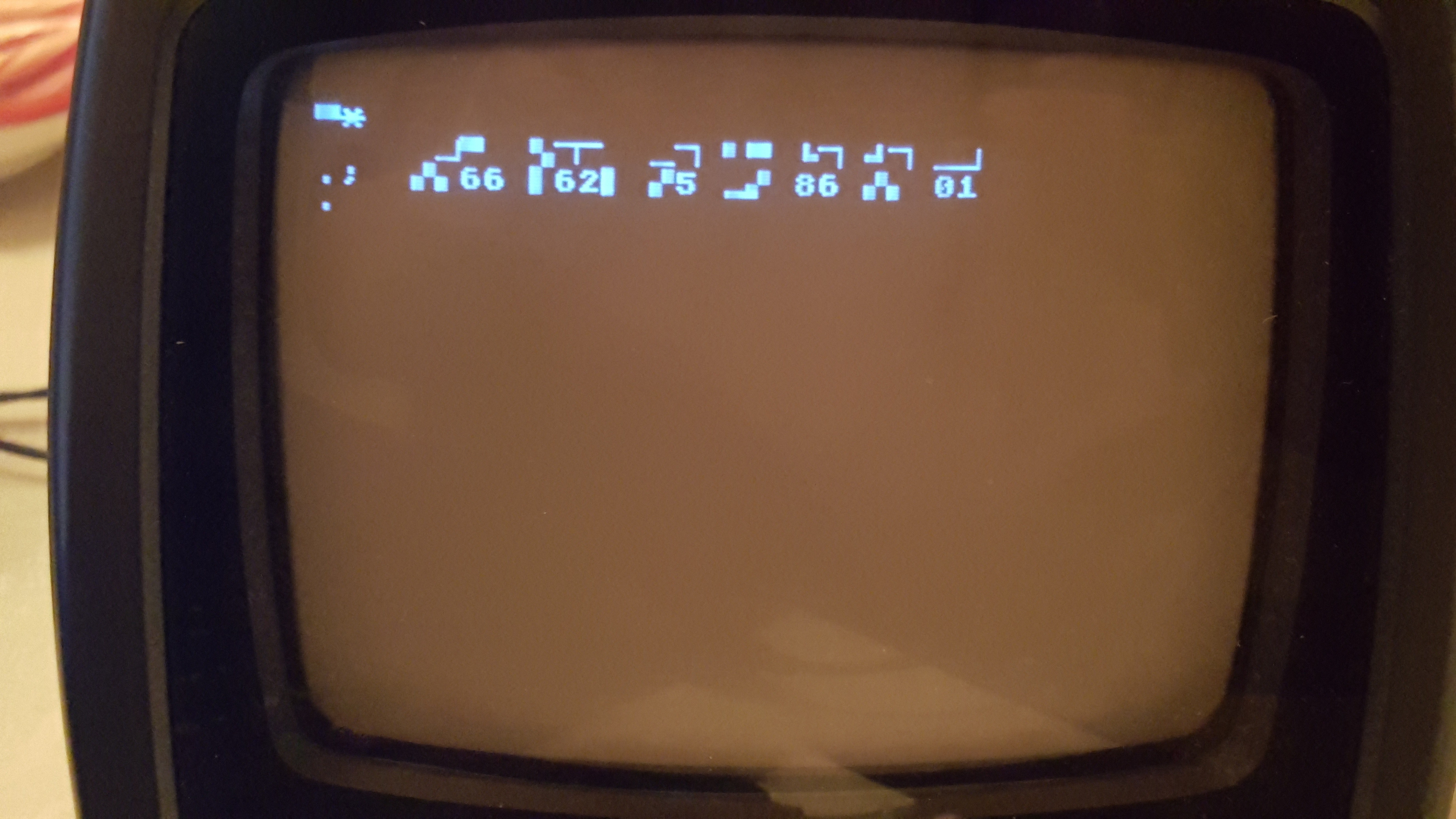
    I intended to get this done last weekend for the 44th birthday of the Apple 1 computer (April 11 1976) but unfortunately it wasn't meant to be. After I had put the circuit together, it didn't work at first. The 65C02 that I was using, had given the ghost, possibly because of me being careless with static electricity. I checked all the wiring first (which took a long time) and when everything checked out, I wrote a short program to slow the 6502 clock down to a crawl of 1 Hz or so, and write the INA input register to the screen on every clock cycle. That finally showed that the address bus and data bus were the same on every cycle, so the 65C02 wasn't running.

    After I replaced the 65C02 with another, everything worked just like it should, but by then it was Tuesday. Then I got some "distractions" from work and family life, and I could finally get back to it on Friday.

    I replaced the instructions section of the project here on Hackaday with instructions on how to breadboard your own L-Star for (probably) less than $50. Have fun!

    Oh, and by the way, I got parts for a batch of L-Star Plus kits. It will be back in stock some time this weekend. YAY!

  • L-Star As a SuperCon2018 Badge Add-On

    Jac Goudsmit11/05/2018 at 19:27 4 comments

    Apple-1 emulator for SuperCon2018 Badge

    I turned my SuperConference 2018 Badge Add-on board into a 6502 computer, so if you're tired of playing Zork on a Z80, you can play Super Star Trek on an Apple 1 emulator.

    I didn't win the badge hacking competition, though I think I might have had a good chance to at least be admired on stage if I would have had 5 more minutes with a soldering iron; the add-on was basically working but it was disconnected from the badge because of a wiring mistake that I didn't notice until after all the soldering stations had disappeared.

    Read more »

  • PET-2001 Emulator Project Started

    Jac Goudsmit06/11/2018 at 20:02 2 comments

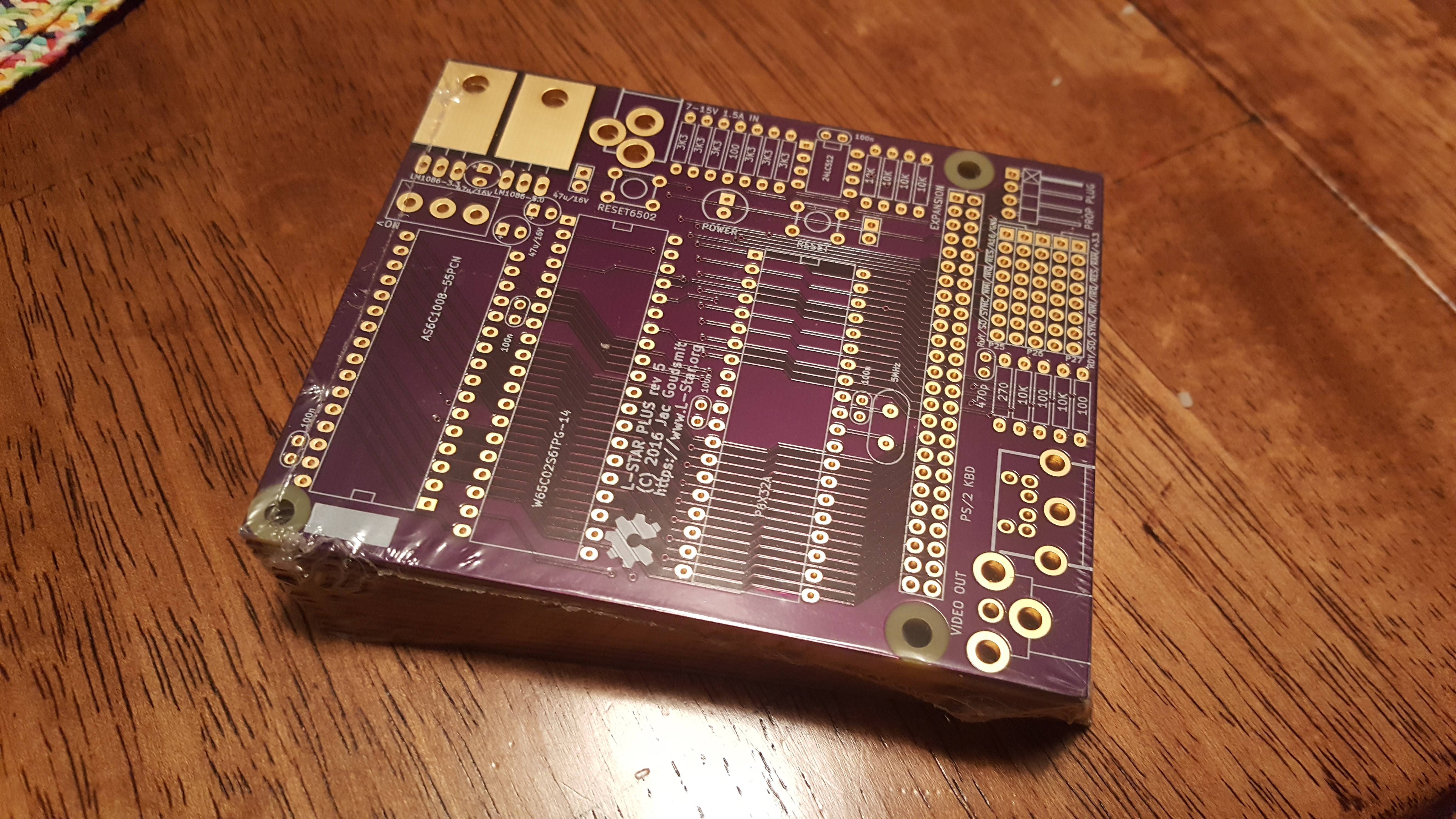
    If you've followed me long enough, you know that my original purpose for the #Propeddle: Software-Defined 6502 Computer project was to build a replica of the Commodore PET-2001 and CBM series computers. The PET-2001 was the first computer I ever used, when I was about 11 years old in 1978. And now I've finally made a start on writing a software-defined computer project to emulate the PET/CBM on L-Star. As you can see in the picture, I have a long way to go.
    Read more »

  • Back in Stock!

    Jac Goudsmit05/26/2017 at 06:38 3 comments

    Got parts, got PCB's, getting Prop Plugs in a day or two.

    That means L-Star is back in stock!

    Order here: https://www.tindie.com/products/jac_goudsmit/l-star-plus-software-defined-6502-computer/ (or click on the Tindie link on the project page).

  • Some Ideas for the Future...

    Jac Goudsmit01/12/2017 at 23:05 4 comments

    I received the second batch of production boards and parts, so the kit is back in stock on Tindie. Meanwhile, I figured I should write down what the plans are, especially for the l-star.org website. See "after the break" for some ideas I'm working on.

    First of all, I've been working some tutorials for owners (or those who want to follow along at home) to learn how to "write their own computer" using the C language:
    • The first tutorial/demo proposes a basic framework that defines types and macros to get started, and generates a clock signal "as fast as possible" and lets you observe how the 65C02 reset sequence works
    • The second tutorial/demo shows how to run a separate cog that presents part of the Propeller's hub memory to the 65C02
    • The third tutorial/demo shows how the PIA of the Apple 1 can be emulated in C, and loads the ROM from Vince Briel's Replica 1 to make the L-Star into an Apple 1 emulator.

    The code for the above is already on Github here, but I'm still working on the text that will be posted on the website soon.

    Future Tutorials

    I'm thinking the next tutorials should be:

    • How to convert time-critical code into inline assembler, and how to use a Propeller timer as clock generator.
    • How to use the SRAM chip.
    • How to implement emulation of memory-mapped (text) video, and how to emulate a matrix keyboard, culminating into an emulator of the Ohio Scientific Challenger C1P (also known as the Superboard II or UK-101).
    • How to implement a virtual storage device using the EEPROM.
    • How to make up your own system, maybe running Forth.

    Future Hardware

    I have several ideas I want to work on in the hardware area:

    • Commodore PET emulator: this is what I originally intended the project to do, but it would need a way to generate interrupts at 60Hz or 50Hz and I'm trying to think of a way to do that without adding extra hardware.
    • Acorn Atom (a.k.a. Hob-bit computer) emulator; this should also be possible without extra hardware.
    • An expansion board with 24 (or more) tactile switches and six or eight 7-segment displays to emulate a Kim-1 or Elektor Junior
    • A "Pro" version for advanced experiments: this would probably be a version of the board that doesn't have the I/O and jumpers on board; it would have a right-angle connector for expansion, which would plug into a new passive motherboard (or simply an IDC connector on a ribbon cable) to connect to multiple expansion boards. Or, going slightly further, something resembling RC2014 but perhaps using card edge connectors.
    • A "Pro 16" version that uses a 65C816 instead of a 65C02 and has (say) 4MB of static RAM and runs faster while the CPU is not accessing the Propeller. This could perhaps be used to emulate the Mensch Computer or simply to run Fuzix. You know, just for giggles.
    • A modification to use a PIC microcontroller instead of a Prop Plug to connect it to a host system. This would eliminate the FTDI controller, the one and only chip in the design that's not available in a DIP package, and would make it easier to put the system into an enclosure.

    Are You Still Reading?

    I have disappointingly little time to get all this stuff done, and I hope owners and enthusiasts will step up to help some day. Whether you have a kit or not, if you've read through the documentation and you can think of something you want (me) to do with the L-Star, or if you would like to propose any ideas for expansion boards or software projects, let me know!

  • Now For Sale on Tindie!

    Jac Goudsmit11/08/2016 at 05:34 0 comments

    I received the PCB's for the first production run!

    That means you can now actually buy the project as a kit on Tindie. Click the link on the project page to order.

    I'll be setting up the web site at l-star.org this week (hopefully), so that new owners will have a place to go to find build instructions, documentation, and maybe even a forum to share what they've done with the system, ask questions, or make suggestions. If it's going to be a lot of work, it means I'm doing it right!

    ===Jac

  • Hardware Revision 5: Could This Be the One?

    Jac Goudsmit10/11/2016 at 04:15 0 comments

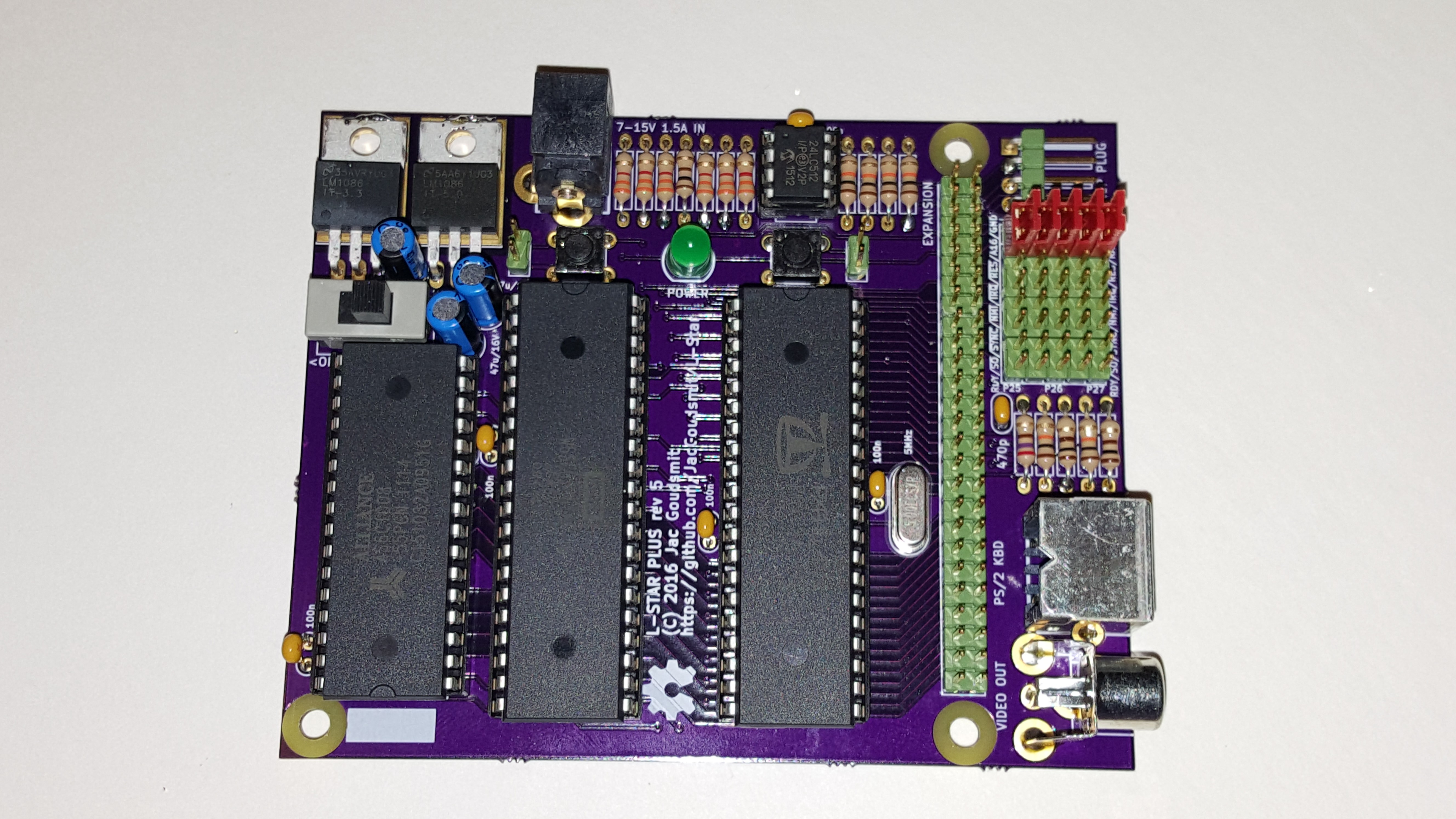
    After the disaster with Rev. 4 (see the last log), I learned a couple of things and made some changes resulting in Rev. 5:

    Read more »

  • So Much Fail: Building the Rev. 4 Boards.

    Jac Goudsmit09/13/2016 at 07:09 1 comment

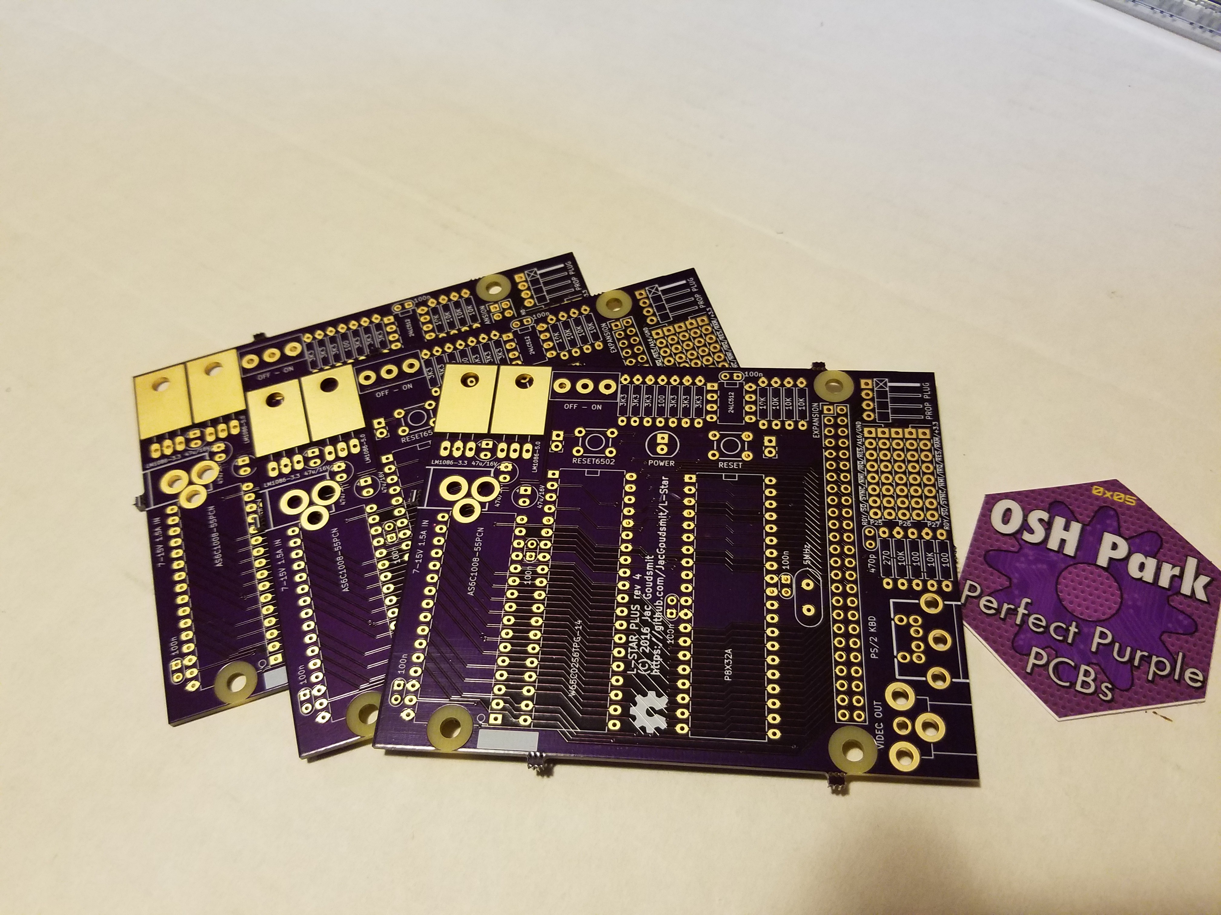
    Last Friday, the Rev. 4 boards arrived from OSHPark, and a Purple PCB Day is always a good day. Also, BBC America was doing their Star Trek 50th Anniversary Marathon of all the Original Series episodes and I was the only one home, so this was going to be a fun night of watching the young version of Khan, Zefram Cochrane and the Tribbles, and soldering my project together. Or not?

    Two of these are not like the others...

    Read more »

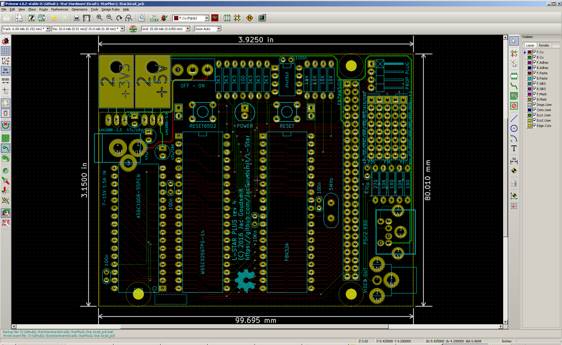
  • Hardware Revision 4: Now with All the Pins You Need!

    Jac Goudsmit08/28/2016 at 22:08 0 comments

    This weekend I was able to do some work on the hardware of the project again, and I decided to bump the version number, so it is with pride and joy that I announce Revision 4 of the L-Star hardware.

    Read more »

  • Hardware Revision 3

    Jac Goudsmit06/15/2016 at 03:27 2 comments

    As I mentioned in the "Hardware Revision 2" posting, there were some small but significant problems with that version of the schematic and PCB:

    • The ~RAMEN pin ended up in the wrong place on the jumper block, which would make it difficult to use video, a keyboard and the on-board SRAM chip at the same time.
    • With the added on/off switch, the board got a little crowded around the RESET6502 button which made it harder to press the button. Also I didn't like that the buttons didn't line up nicely in the layout anymore.
    • The board still had the old problem that the solder islands for most parts/footprints were a bit on the small side.

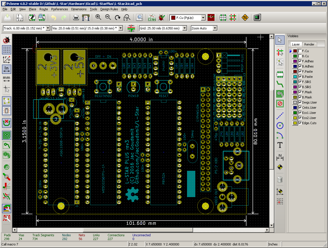
    Here's a picture of the Revision 3 layout:

    First of all, I switched the location of A16 and ~RAMEN (and the accompanying 3.3V and GND pins) so that ~RAMEN can be jumpered to P27 which is connected to KBCLK in the "default" configuration. I considered moving things around so that ~RAMEN would be the default for P27 and KBCLK would be an alternative, but I decided it would cause too much confusion so I didn't do that.

    I moved the power LED to a location between the pushbutton switches, so now there should be enough space for a finger to push the button again. I also lined the pushbuttons up, close to the places where they were in revision 1. The LED is in a sort-of-odd place, so far away from the power connector and the power switch, but it's where there was enough space for the traces. I would have liked it on the right side of the board (and the power switch too) because I imagine that side will be pointing towards the user, but that's simply impossible unless I make the board a lot bigger.

    I edited all the footprints on the board and made sure that they all use solder islands with a size that's big enough to solder if you have a non-professional solder iron, or if (like me) you have some old solder tin that doesn't flow as well as it used to do.

    I discovered another oversight that I wanted to fix: the jumpers didn't have the ~RESET6502 signal on them. So I changed the jumper block from 7-by-5 to 8-by-5 and added the signal near the top, where it was easy to line up with the ~RES6502 pin on the expansion port connector. As it turns out, this had a fortunate side-effect: I found out that five 10-pin pin headers are cheaper than two 20-pin headers of the same series (the ones with the green plastic that I got by mistake but look really good and nicely define the color scheme of the project, along with the purple PCB and the red jumpers). This will make it easier to break/cut the jumpers to size for the final kit.

    I also made the footprint of the voltage regulators a little smaller, which allowed me to reduce the board size again, and to line up the power switch with the RESET6502 pushbutton.

    I haven't ordered parts or PCB's yet, because I'm considering another change: I'm thinking of putting the voltage regulators upright, and wiring them up differently so they'll be in parallel instead of in series. This will allow expansion boards to use more power on the 5V rail (the 3.3V regulator is currently fed by the 5V rail) and might reduce heat production because the current only has to go through one regulator instead of two. On the other hand, it might cause other problems like interference and the need for bigger electrolytic capacitors.

    Another change I'm considering is to use a 50-pin expansion header instead of a 40-pin one. You may have noticed that there is just enough space to do that, and that's not a coincidence. A 50-pin header would make it possible to run the video and keyboard connectors to the expansion board, as well as some signals (~BE, A16, ~RAMEN) that I had to leave out because of the 40-pin limit. This would make it possible to design an expansion board that e.g. generates color video and uses the PS/2 keyboard, without the need to add connectors for them to the expansion board. And it would be possible to let an expansion board take over some functions take over some functions that currently only...

    Read more »

View all 14 project logs

  • 1
    A Minimal L-Star on a Breadboard

    These instructions describe how to wire up a minimal version of L-Star on a breadboard, and make it work as an Apple 1 replica. If you would like to know how the Apple 1 works, and you don't have much time or money, this is probably the project for you. And because it's on a breadboard, you can re-use the parts for something else once you get tired of it.

    The Propeller microcontroller that I used for the L-Star project, needs quite a bit of peripheral hardware to make it useful. Parallax, the company that makes the Propeller, recognized this and they make the Propeller FLiP module available (their item number is 32123). The FLiP is more expensive than the Propeller of course, but it not only has the Propeller on board and gives you access to all I/O pins, but it also has an EEPROM, an FTDI chip for USB communication with a computer, a few LEDs for debugging, and a power supply that can use either the USB connection or an external power source as input, and generates 3.3V as well as 5V as output. The photo below shows two FLiP modules: one from the top and one from the bottom.
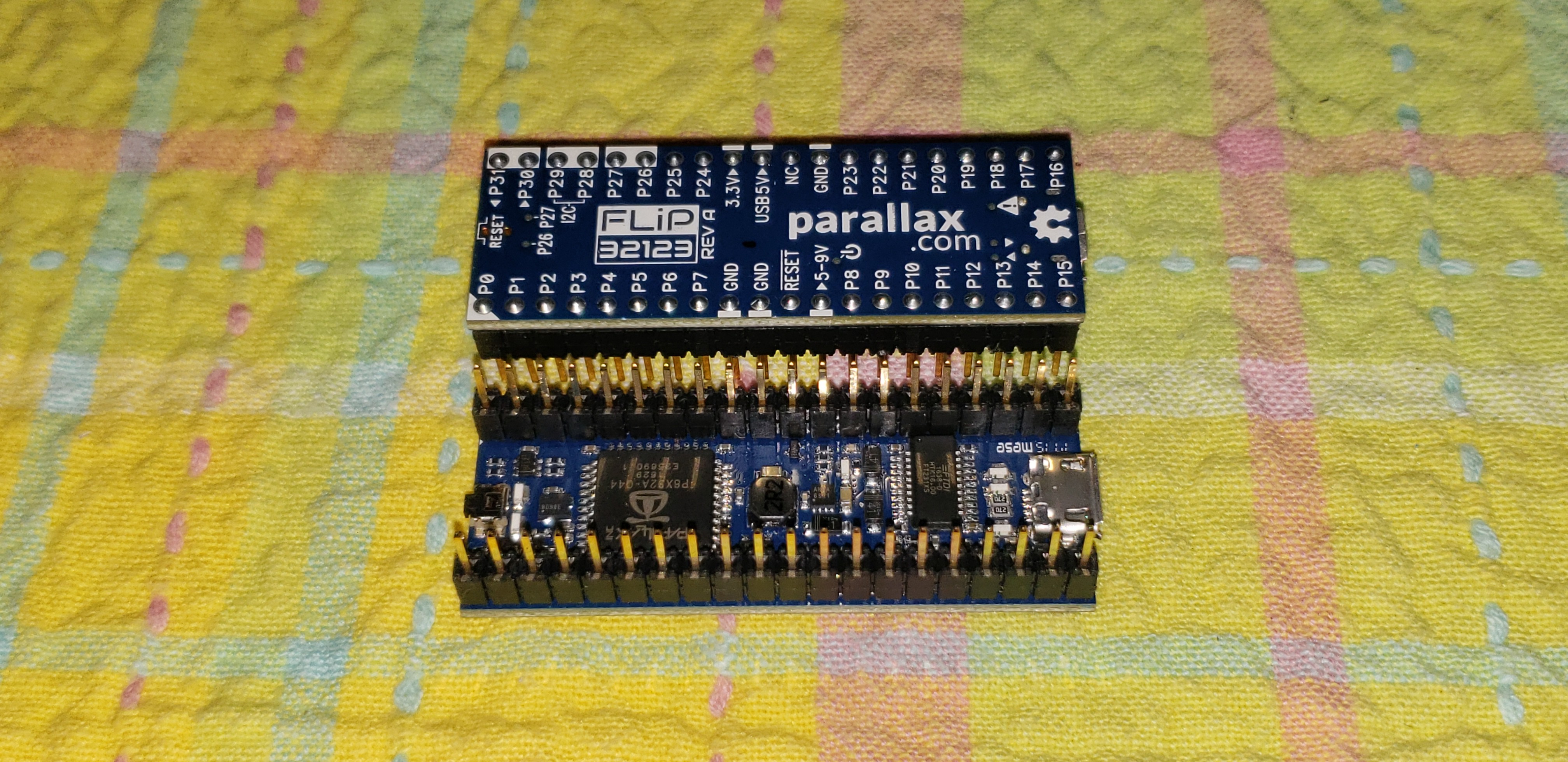
    The Propeller FLiP and a WDC65C02S (the version of the 65C02 that's still in production) are almost all you need to make a working Apple 1 replica. All that's missing is a breadboard with at least 50 columns, 2 resistors of 10K, and some wire.

  • 2
    Getting Started: Mount the FLiP module and the WDC65C02S

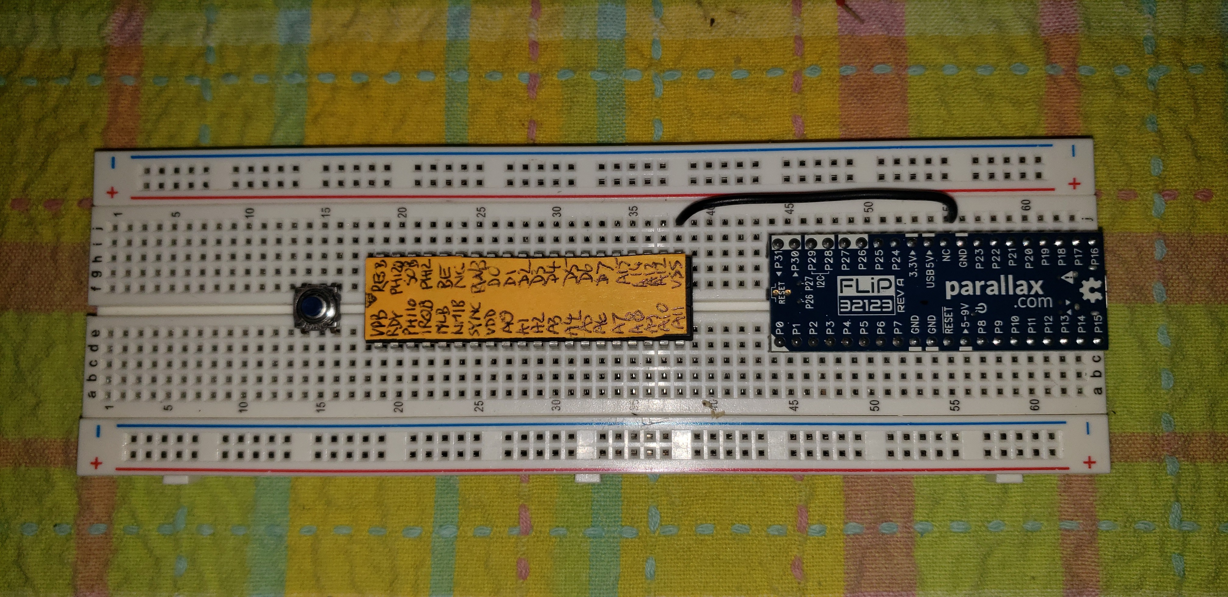
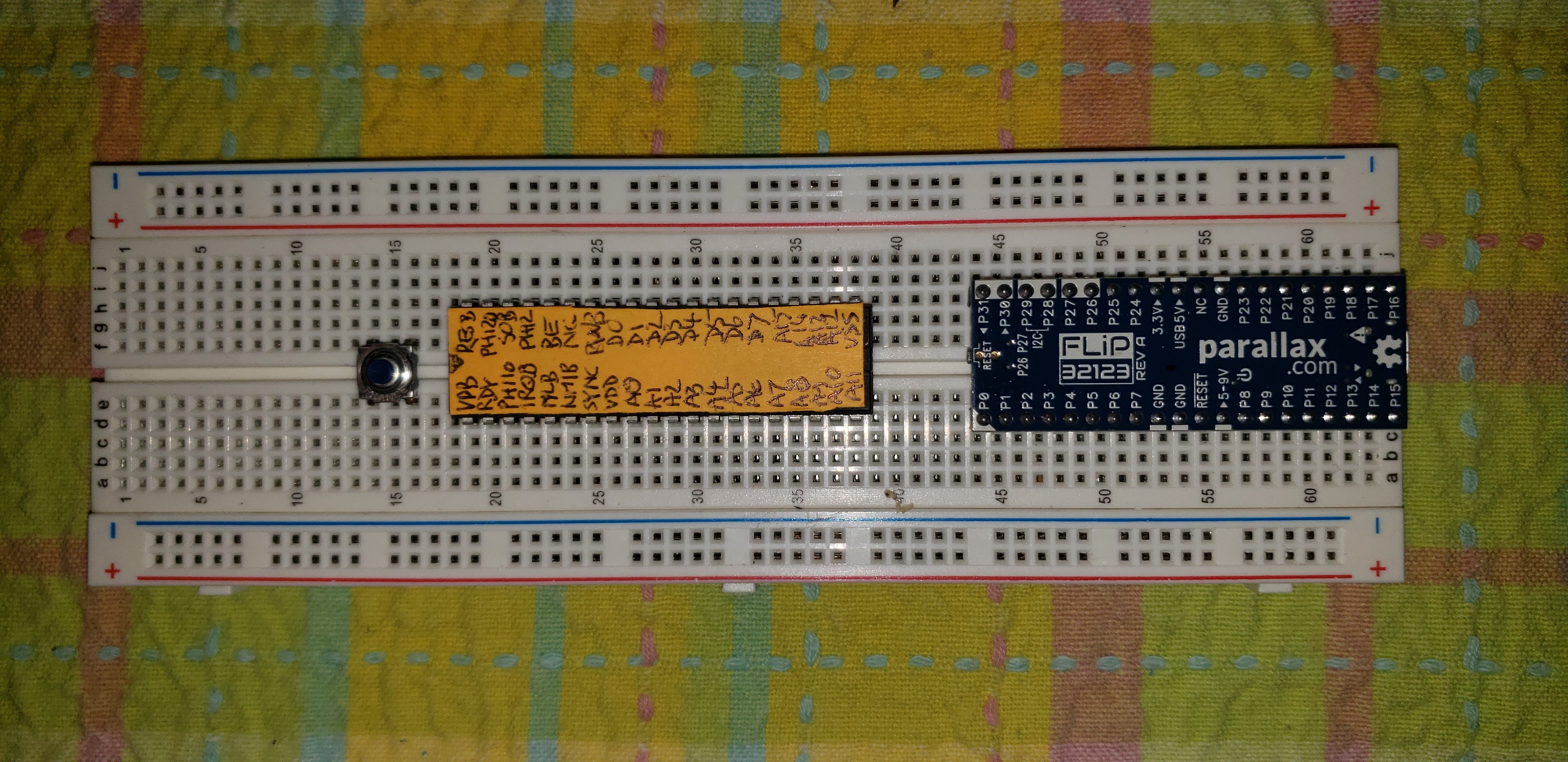
    Mount the FLiP all the way to the right of the breadboard, with pin 1 (indicated by the triangle) pointing to the bottom left. The USB connector of the FLiP is at the edge of the breadboard that way so you can easily connect it. Leave 2 rows of the breadboard free above the top of the FLiP and 3 rows at the bottom.

    Leave 5 columns free between the WDC65C02S and the FLiP, for wires that will go there and to leave space for your finger to push the Reset button on the edge of the FLiP. Leave 2 rows of breadboard free above the WDC65C02S and 3 rows at the bottom. Pin 1 of the WDC6502S should be at the bottom left, so the notch on the chip should be on the left.

    I cut up a large sticky note so it matched the size of the WDC65C02S, and I stuck it to the chip. Then I wrote the names of the pins on it with the help of the Data Sheet. This really helped me make sure that I didn't make mistakes so I highly recommend it.

    The pushbutton that will be used as reset button for the WDC65C02S is on the left of the chip with 2 unused columns in between.

    You can decide to make your own variations on the circuit of course, but I put the WDC65C02S and the FLiP and the reset button in these exact locations for a good reason: It left exactly enough space on the left to add some optional components that I'll get back to later.

  • 3
    GND and Power

    GND: FLiP pin 29 to 6502 pin 21

    To avoid any mishaps with static electricity, it's probably a good idea to start by connecting GND of the FLiP to VSS of the WDC65C02S (can I just call it "the 6502" from now on? Thanks!).

    3.3V: FLiP pin 32 to 6502 pin 8

    The original 6502 that came out in 1975 worked on 5V, but the Propeller uses 3.3V as power supply, and doesn't like it when its I/O pins get fed with 5V. So in the L-Star project, we feed the same 3.3V to the WDC65C02S which (unlike its MOS predecessor in the old days) is perfectly fine running at that voltage.

View all 11 instructions

Enjoy this project?

Share

Discussions

Similar Projects

Does this project spark your interest?

Become a member to follow this project and never miss any updates