
-
Electronics & Microcontrollers for Absolute Beginners (Part 14)
02/04/2021 at 22:18 • 2 commentsWell, hello there, how nice to see you again. Everything we’ve talked about thus far has laid the foundation for what is to come. In the case of this column, this means we are poised to perform our first hands-on experiments with real electronic components. This is going to be tremendously exciting, so make sure you are sporting appropriate attire (I favor floral Hawaiian shirts myself).
Resistors
If there’s one thing we tend to use a lot of when we are creating electronic circuits, that thing is resistors. At the end of Part 12, I recommended that you purchase a resistor kit containing a bunch of different 1/4-watt, 5% tolerance components, something like this resistor kit comprising 1,800 pieces spanning 72 values will do nicely (the comments say their leads are a little on the thin and flimsy side, but overall they have a good rating).
As I’ve mentioned before, please note that I have NO connection with and receive NO remuneration from anyone associated with any of the components and tools I may mention in these columns.
Diodes
Diodes are interesting components in that they conduct electricity only in one direction (we’ll see this in action shortly). The first diodes were created using vacuum tube technology, but we now use semiconducting materials like silicon or germanium. As fate would have it, we won’t be using any regular diodes in this column, but if you really start getting into electronics, you’ll discover that it’s a good idea to have some standard parts close to hand. On this basis, I would suggest something like this diode kit.
Light-Emitting Diodes (LEDs)
There are various types of diodes, each with different characteristics. One type is called a light-emitting diode (LED). As for a regular diode, an LED conducts electricity only in one direction. Unlike a regular diode, however, when the LED is conducting, it also emits electromagnetic radiation (ER). We are typically talking about ER in the form of the visible spectrum -- red, green, yellow, orange, blue, etc. -- but other types of LEDs, like ones that emit infrared (IR), are also available. If you are anything like me, you will end up using a lot of LEDs in your projects -- also, we will be using them in our experiments in this column -- so I think it would be a good idea to splash the cash on something like this LED kit.
9V Battery and Clip
In addition to our resistors and diodes, there are a couple more things we are going to need for the experiments in this column. First, we require something to power our circuit. Just to make things easy, we are going to use a standard 9 V (9-volt) battery. You can, of course, pick one of these up at your local supermarket (but not at a gas/petrol station because they will overcharge you by so much that it will make your eyes water). Note that the smaller connector is the positive (+ve) terminal, while the larger “splayed out” connector is the negative (-ve) terminal.
Now, we could just hold our wires onto the battery terminals with our hands, and you are certainly free to do so, but we can also make our lives a lot easier by using a battery clip. In an earlier column I noted that it’s a good idea to start building up a “treasure chest” of components and other useful items. In this case, on the basis that they will almost certainly come in handy at one time or another, you might consider purchasing something like this 10-pack of 9 V battery clips.
“A LED” or “An LED”?
When you are reading books or articles about electronics, you may see the author write “a LED” or “an LED” -- so, which one is correct? Well, like so many things, the answer is “it depends.” In this case, it typically hinges on how the author sounds things out in his or her head, although it may also be determined by an in-house style guide. If, while chatting, someone says “LED” to rhyme with “bed,” then “...
Read more -
Electronics & Microcontrollers for Absolute Beginners (Part 13)
12/30/2020 at 23:06 • 2 commentsJust to make sure we’re all tap-dancing to the same drum beat (and I know whereof I speak, because my dear old dad used to be a dancer on the variety hall stage prior to WWII -- see The Times They Are a-Changin’), let’s remind ourselves that in Part 12 we introduced two multimeters -- a regular digital multimeter that I picked up from RadioShack years ago, and an Auto-Ranging device I purchased from Amazon able to talk about in these columns.
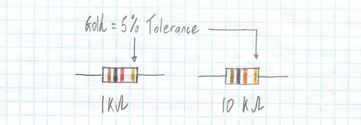
At the end of Part 12, I recommended that you purchase a resistor kit spanning a range of resistance values with a 5% tolerance. So, let’s start by selecting two resistors from our kit: a 1 kΩ (1,000 ohms) with brown-black-red bands and a 10 kΩ (10,000 ohms) with brown-black-orange bands (we described the colored bands in Part 11).
![]() Graphical representation of 1 kΩ and 10 kΩ resistors (Image source: Max Maxfield)
Graphical representation of 1 kΩ and 10 kΩ resistors (Image source: Max Maxfield)
For our initial experiments, we’ll use our regular multimeter, which -- in my case -- is my cheap-and-cheerful RadioShack device.
![]() My regular RadioShack multimeter (Image source: Max Maxfield)
My regular RadioShack multimeter (Image source: Max Maxfield)
The reason I call the RadioShack device a “regular” multimeter is that it’s up to the user to use the rotary switch to select the most appropriate voltage, current, or resistance range before making the measurement. In the case of resistance (the “OHM” area of the rotary switch), which is the topic of this column, we have five options: 200, 2K, 20K, 200K, and 2M ohms.
Why do we need these options? Well, selecting the appropriate setting allows us to make the most accurate measurement. This can be confusing if you are a beginner, so let me give you an analogy. Suppose you have two devices you can use to measure the length of something -- let’s say a small ruler with millimeter and centimeter markings and a piece of rope that’s 10 meters long with splashes of paint to mark every meter.
Now, let’s assume you want to measure the diameter of a penny coin. Not surprisingly, you will obtain the best results if you use the small ruler. By comparison, if you wish to determine the distance between your house and the home of a friend who lives at the far end of a long, straight street, then you’ll find the rope better meets your measuring requirements. Remember that analogies are always suspect, and this one doubly so (for all sorts of reasons), but the underlying concept is sound.
Another way of thinking about this is that, at the core of an ohmmeter (the portion of a multimeter used to measure resistance) is a potential divider formed from two resistors we might call R1 and R2 (potential dividers were introduced in Part 7).
Let’s suppose that the value of R1 is known because it’s inside the multimeter, while the value of R2 is unknown because it’s the one we’re trying to measure. For the purposes of what we are trying to do here -- that is, measuring the value of R2 as accurately as possible -- it will make our task easier if the values of R1 and R2 are relatively close together. By comparison, if the value of R1 is say vastly different to that of R2 (say 100 times larger or 100 times smaller), then this will make the task of measuring R2 with any useful level of precision much harder.
Take another look at the previous image. We’ve selected the 20K option, but the probes aren’t connected to anything yet, so the meter displays O.L. As we noted in our previous column, this means “Open Line” (some people may say “Open Loop,” while others may say “Open Circuit”), and it is used to indicate infinite resistance when the probes aren’t connected to anything or if there is no conducting path between whatever the probes are connected to.
Interestingly enough, the actual “OL” presentation depends on the selected range. Even more interesting (at least to me) is that the first time I actually noticed this was when I started to write this column. The various display formats for my meter are shown below (I have no...
Read more -
Electronics & Microcontrollers for Absolute Beginners (Part 12)
12/04/2020 at 15:40 • 4 commentsIn Part 9 of this mini-mega-series, we mentioned the fact that we can use special tools called voltmeters to measure voltage, ammeters to measure current, and ohmmeters to measure resistance. We also have multimeters, which can measure voltage, current, and resistance, along with a variety of other things, depending on the meter.
It's possible to get all of these meters with either analog or digital displays. For the purposes of these columns, however, we will assume we are working with a multimeter of the digital variety.
A digital multimeter is one of the most useful items in any electronic engineer’s toolbox. You can spend a lot of money on professional, industrial-grade multimeters, but you can also get a very serviceable device for not much money at all. For example, I just had a quick Google (while no one was looking) and found the AstroAI Digital Multimeter (with 4.5 stars from 9,361 ratings) for only $12.99 from Amazon Prime (please note that I have NO connection with, and receive NO remuneration from, anyone associated with any of the components, devices, and tools I may mention in these columns).
Take a look at the photo below. On the left we see a regular cheap-and-cheerful digital multimeter that I picked up from RadioShack years ago and that I use all the time. Observe that this doesn’t have any ports (connectors) per se -- the black and red probe leads just come straight out of the case. On the right we see an ETEKCITY Auto-Ranging Digital Multimeter (with 4.5 stars from 973 ratings) that I purchased for $18.99 from Amazon Prime just to be able to talk about it in these columns.
![]() Two low-cost digital multimeters: a regular unit (left) and an auto-ranging unit (right) (Image source: Max Maxfield)
Two low-cost digital multimeters: a regular unit (left) and an auto-ranging unit (right) (Image source: Max Maxfield)
Observe that both of these meters are currently set to measure resistance and are displaying different versions of “OL” meaning “Open Line” (some people may say “Open Loop,” while others may say “Open Circuit”). This is used to indicate infinite resistance when the probes aren’t connected to anything or if there is no conducting path between whatever the probes are connected to.
With regard to the ETEKCITY multimeter, observe that this has three ports (connectors). The black probe is plugged into the COM (“common”) port. This is the probe that is usually connected to the ground (0V) or negative (-ve) part of a circuit. The red probe is plugged into the port marked “VΩmAµA,” which indicates that this port can be used to measure voltage, resistance, and current (in both milliamps and microamps). Different meters will have different annotations on this port, like “VΩmA” or “mAVΩ,” but these are just different ways of indicating the same thing.
Also observe the port with the 10A annotation. This is a special port that is intended to be used only when measuring large currents. As a beginner, you should NEVER be interested in measuring currents larger than a few hundred milliamps, so do your best to forget that the 10A port even exists.
The reason I call the RadioShack device a “regular multimeter" is that it’s up to the user to turn the rotary switch to select the most appropriate voltage, current, or resistance range before making the measurement. In the case of resistance, for example, we have five options indicating 200, 2K, 20K, 200K, and 2M ohms (we’ll discuss this more in my next column).
By comparison, in the case of the ETEKCITY multimeter, the “Auto-Ranging” part of its moniker comes from the fact that all we have to do is set its rotary switch to the Ω (resistance) annotation, and it will automatically work out the most appropriate range when we use the probes to measure the value of a resistor.
Which is best -- a regular multimeter or an auto-ranging device? Well, to a large extent this is a matter of individual preference. One way to think about this...
Read more -
Electronics & Microcontrollers for Absolute Beginners (Part 11)
10/20/2020 at 16:21 • 0 commentsAs noted in our previous column, in the not-so-distant future we’re going to start creating simple circuits using resistors and light-emitting diodes (LEDs), but we first need to learn enough about resistors to ensure we use the right ones when the occasion demands.
Unfortunately, it isn’t realistic for a manufacturer to create a collection of resistors comprising every conceivable value in a cost-effective manner. Furthermore, the people who use resistors couldn’t afford to purchase all of the different values and wouldn’t have the space required to store them if they did.
The solution arrived at by the industry was to adopt a selection of standard values, which has the added advantage of allowing users to second-source their resistors from multiple manufacturers. The real trick was for everyone to agree on the values forming the standard set.
As we discussed in Part 10, in 1877, a French military engineer called Charles Renard proposed a scheme of preferred numbers that allowed the French army to reduce the 425 different sizes of ropes they required to keep their balloons in the air to only 17 sizes that covered the same range.
In Renard's system, the interval from 1 to 10 was divided into 5, 10, 20, or 40 steps, which we now refer to as the R5, R10, R20 and R40 scales.
The E Series of Preferred Numbers
In 1952, the IEC (International Electrotechnical Commission) defined a set of standard values for different types of components, including resistors. Collectively referred to as the “E series,” this actually consists of the E3, E6, E12, E24, E48, E96 and E192 series, where the number after the 'E' designates the quantity of value "steps" in each series.
Let’s start by looking at the E12 series. One way to represent this mathematically is as follows (where the symbol ≈ means “approximately equal to”):
10(0/12) = 1
10(1/12) ≈ 1.2
10(2/12) ≈ 1.5
10(3/12) ≈ 1.8
10(4/12) ≈ 2.2
10(5/12) ≈ 2.7
10(6/12) ≈ 3.3
10(7/12) ≈ 3.9
10(8/12) ≈ 4.7
10(9/12) ≈ 5.6
10(10/12) ≈ 6.8
10(11/12) ≈ 8.2
10(12/12) = 10Another way we can look at this is graphically as shown below. Since this scheme is based on a logarithmic approach, and since the E12 series employs 12 subdivisions, observe that each new number can be generated by multiplying the previous value by 10(1/12) ≈1.21.
![]() A graphical representation of the E12 scale (Image source: Max Maxfield)
A graphical representation of the E12 scale (Image source: Max Maxfield)
Remember that these values repeat for every decade, which means we can summarize them in a table as shown below.
![]() A tabular representation of E12 resistor values (Image source: Max Maxfield)
A tabular representation of E12 resistor values (Image source: Max Maxfield)
Through-Hole vs Surface-Mount
Warning -- incoming abbreviation storm! There are two main ways to attach electronic components to printed circuit boards (PCBs). The first is through-hole technology (THT), which is also known as lead through-hole (LTH). The second is surface-mount technology (SMT), whose components may be referred to as surface-mount devices (SMDs).
In the case of THT, component leads are run through copper-plated holes that pass through the PCB. Solder is then applied to attach the component leads to copper pads associated with the holes. By comparison, in the case of SMT, the SMDs are soldered onto pads on the surface of the board. For the purposes of these columns, we will be working with THT components whose leads we will plug into holes in breadboards (don’t worry; all will become clear when the time is ripe).
Resistor Color Codes
Resistors come in many different shapes and sizes. In these columns, we will primarily be playing with...
Read more -
Electronics & Microcontrollers for Absolute Beginners (Part 10)
09/24/2020 at 18:08 • 5 commentsIn the not-so-distant future, we’re going to start creating simple circuits using resistors and light-emitting diodes (“Ooh, Shiny!”). However, in order to warm ourselves up for this awesome experience, we first need to learn a little more about resistors to ensure that we use the right ones when the occasion arises.
Before we start, I’m going to make the assumption that you’ve read the previous columns in this series, which means you should have at least a vague idea as to what a resistor is and what it does. If not, this would be a really good time to do so (LOL).
Also, before we start, a small word of warning. Do you remember being introduced to the concept of logarithms at school? Did you enjoy meeting them as much as I did (which is to say, not a lot)? Well, I’m afraid we are going to lightly touch on them here, but you don’t need to worry because it’s not going to hurt (me) at all.
As an aside, if you aren’t comfortable with logarithms, which were introduced by the Scottish mathematician, physicist, and astronomer John Napier in 1614 as a means of simplifying calculations, then this would be a great topic for you to read up on in your own time, because they have all sorts of cool attributes and uses (you might also want to check this Intro to Logarithms Video from the Khan Academy).
Different Types of Resistors
Resistors can be created from a wide variety of materials using a multiplicity of techniques. If you hang out with dubious people in strange places, you may hear talk of Carbon Composition, Carbon Film, Ceramic, Metal Element, Metal Film, Metal Foil, Metal Oxide Film, Thick Film, Thin Film, and Wirewound resistors (and I wouldn’t be surprised to discover that I’ve left some out).
Each type of resistor has its own advantages and disadvantages. For example, one type of resistor may cost more than another, but its resistance may not vary as much with changes in temperature, which may be an important attribute for a particular application. Happily, for what we are doing here, we really don’t have to worry about any of this. For the purposes of these columns, we are going to use the cheapest, most common resistors we can lay our hands on (I’ll guide you in this later).
Standard Resistor Values (a Little History)
As we will come to see in future columns, when we design an electronic circuit, we may perform some calculations, wave our hands in the air, perform an interesting dance, and decide that -- in an ideal world -- we would like to use a resistor with a value of exactly X ohms.
One solution would be to handcraft individual resistors with whatever values we wish, but this would be resource-intensive and time-consuming, to say the least. Alternatively, it would potentially be possible for resistor manufacturers to offer bespoke services where we tell them what we want and they build to order (BTO), but this would take lots of time and be tremendously expensive. Furthermore, neither of these options work well if the intention is to create large numbers of products with interchangeable parts.
What we really need is access to affordable, off-the-shelf resistors that are available when we require them. Unfortunately, the folks who manufacture resistors simply cannot create and supply every conceivable value in a cost-effective manner. And, even if every possible value was available, the people who use resistors couldn’t afford to purchase all of the different types and wouldn’t have the space required to store them if they did.
The solution arrived at by the industry was to adopt a selection of standard values, which had the added advantage of allowing users to second-source their resistors from multiple manufacturers. The real trick was for everyone to agree on the values forming the standard set.
Before we proceed, there’s an important topic we need to introduce, which is that of “tolerance.” In this context, tolerance refers to the limits of variation of a resistance...
Read more -
Electronics & Microcontrollers for Absolute Beginners (Part 9)
09/01/2020 at 18:49 • 3 commentsSupposing I were to tell you that I know three people: an average-sized kid, a regular-sized adult, and a beanpole of a basketball player. Let’s assume that, earlier today, I used my handy-dandy tape measure to determine that the kid is exactly 4-feet tall, the adult is 6-feet tall, and the basketball player is 8-feet tall.
Now, suppose I were to inform you that these three people are currently in close proximity to each other and they are all looking in the same direction. Assuming that there’s nothing to block anyone’s view, which of these characters do you think will be able to see the farthest?
Your initial reaction may be to choose the basketball player, but you are making a number of assumptions, not the least being that you are assuming all these characters are standing up. It might be that the adult is ensconced in a comfy chair while the basketball player is kneeling down, for example (you have to be careful discussing things with engineers because we can be tricky little scallywags if we want to be).
Even assuming that all three of our subjects are standing up, we still can’t guarantee that the basketball player has the advantage. This is because we haven't specified their relationship to each other, which could be as illustrated below.
![]() It's hard to compare things if you don’t first set the ground rules (Image source: Max Maxfield)
It's hard to compare things if you don’t first set the ground rules (Image source: Max Maxfield)
The thing is that it can be hard to compare things if we don’t first set the ground rules (no pun intended). In this case, for example, on the left, we find our 6-foot adult standing on the ground, which places his head six feet above ground level. In the middle, our 4-foot tall kid is standing on a 4-foot tall box, which results in his head being eight feet above the ground. Meanwhile, on the right, our unfortunate 8-foot tall basketball player finds himself standing in a 4-foot deep hole (I hate it when that happens), which leaves his head only four feet above the ground. The end result is that, in this scenario, it’s the 4-foot kid who can see the farthest.
![]() It’s important to establish a common frame of reference (Image source: Max Maxfield)
It’s important to establish a common frame of reference (Image source: Max Maxfield)
The point of all this is that it’s possible for us to measure people’s heights individually, but -- depending on what we are trying to do -- it may be meaningless to compare them with each other unless we first establish some common frame of reference. In the case of our three test subjects, for example, our original question -- “Which one will be able to see the furthest?” -- makes much more sense if we also specify that they are all to be standing close to each other on a level piece of ground as illustrated above, in which case the basketball player will, not surprisingly, have the advantage.
Miscellaneous Meters
In earlier columns, we’ve introduced the concepts of voltage (measured in volts), current (measured in amps), and resistance (measured in ohms).
It may not surprise you to learn we have tools we can employ to measure these little rascals: we can use voltmeters to measure voltage, ammeters to measure current, and ohmmeters to measure resistance. We also have multimeters, which can measure voltage, current, and resistance, along with a variety of other things, depending on the meter.
In the early days (circa the late 1800s and early 1900s), all of these meters were analog in nature, using a moving pointer to display the reading. Later, digital meters with numeric displays arrived on the scene. Today, it’s possibly to purchase analog and digital versions of all these meters.
In a future column, we will talk about digital multimeters in more detail, including where to get them and how to use them to measure things. For the purposes of this column, however, let’s simply assume we have a digital voltmeter, which we can use to measure the voltage difference (more formally, the electric potential difference) between two points in an electric circuit.
A Rose by Any Other Name
The phrase "A rose by any...
Read more -
Electronics & Microcontrollers for Absolute Beginners (Part 8)
08/17/2020 at 18:44 • 6 commentsBefore we start, I would just like to say in a quite and soothing voice, DON'T PANIC!
If you were to quickly glance at the following text and illustrations, your knee-jerk reaction might be to say something like: "Eeek! There are a lot of equations. I don't like math. I'm out of here!" While it's true that there is a little math, all of these equations are "easy peasy lemon squeezy." If you can look at an equation like 6 = 2 * 3 (which is the same as saying 6 = 2 x 3) without fainting, and if you understand that 2 = 6/3 and 3 = 6/2 are just different ways of writing 6 = 2 * 3, then you are totally equipped to follow the rest of this column.
-------------------------------------------------
Last time, in Part 7, we considered circuits with resistors connected in series (one after the other). In this type of circuit, the current can take only one path, which means the current is the same at any point in the circuit.
By comparison, in this column we are going to consider circuits with resistors connected in parallel (side-by-side). In this case, there are multiple paths the current can take, in which case the current may be different in each path.
As usual, and as an aid to wrap our brains around what’s happening, let’s compare an electrical circuit comprising three resistors in parallel to a water analogy with three branches.
![]() Water analogy of a parallel resistor circuit (Image source: Max Maxfield)
Water analogy of a parallel resistor circuit (Image source: Max Maxfield)
With regard to our analogy, let’s assume that the three pipes in parallel have different diameters. As we discovered in the water analogy we used in Part 2, increasing the diameter of a pipe reduces its resistance to the flow of water. Not surprisingly, more water will flow through the pipes with a larger diameter (less resistance). The same thing is true of electricity, which will also take the path of least resistance (pun intended).
Looking at our new water analogy a little closer, we can see that the total water current IT splits up into three smaller currents: I1, I2, and I3. Eventually, these three smaller currents recombine to form IT again. Once again, exactly the same thing happens in the case of our electrical circuit.
OK, now let’s compare our series and parallel circuits in a little more detail. Let’s start with the series circuit shown as (a) in the diagram below.
![]() Comparison of circuits with three resistors in series and in parallel (Image source: Max Maxfield)
Comparison of circuits with three resistors in series and in parallel (Image source: Max Maxfield)
Let’s start by assuming that we know the values of VS, R1, R2, and R3. We also know that, neglecting any tiny voltage drops associated with the minuscule resistance of the wires, the sum of the voltages across the resistors, VR1, VR2, and VR3, will equal the value of the source voltage VS. Last, but not least, we know that the total resistance of this circuit, RT, equals the sum of the individual resistances R1, R2, and R3. Apart from anything else, this means that the value of RT will be greater than the value of any of the individual resistors (I know this seems obvious, but we are setting the scene for what is to come).
Since we know the value of VS and we know the value of RT, we can use Ohm’s law (see Part 5) to calculate the current: IT = VS/RT.
Even better, since we now know the current, IT, we can again use Ohm’s law to calculate the voltage drops across the individual resistors: VR1 = IT * R1, VR2 = IT * R2, and VR3 = IT * R3.
One final point regarding the resistors in series is that, since the current is the same throughout the circuit while the voltage is divided across the individual resistors, this is known as a “voltage divider.” By comparison, in the case of the parallel circuit shown as (b) in the diagram above, the same voltage, VS, is presented to all three resistors while the current is divided between the individual paths, so this is known as a “current divider.”
With regard to the parallel circuit, let’s assume once again that we know the values of V...
Read more -
Electronics & Microcontrollers for Absolute Beginners (Part 7)
07/30/2020 at 19:57 • 3 commentsIn Part 5 of this soon-to-be-epic series of articles. We introduced components called resistors. Also, we discussed the concept of Ohm’s law, which describes the relationship between voltage (V), current (I), and resistance (R).
Later, in Part 6, just for giggles and grins, we added the concept of power, and we noted that when we are designing electrical and electronic circuits, it’s important to do the math before we flip the power switch to its “On” position, otherwise we may find ourselves living in interesting times.
Thus far, we’ve considered a simple circuit with only one resistor, but it’s common to have two or more of these little rascals. One way we can connect resistors is in “series,” i.e., one after the other as illustrated below:
![]() Two resistors connected in series (Image source: Max Maxfield)
Two resistors connected in series (Image source: Max Maxfield)
Now, one thing that often confuses beginners is why we typically only draw one annotated arrow for the current (I) as shown in (a) in the figure above. Why don’t we show multiple annotated arrows as shown in (b) in the figure above? Furthermore, in the same way that we use labels like R1 and R2 for our resistors, why don’t we use labels like I1, I2, and I3 for the currents?
The reason for this is that, in a circuit in which all the parts are connected in series, the current is the same wherever we measure it. In our example circuit, we have the power source (the battery in this case) connected to resistor R1, which is connected to resistor R2, which is connected back to the battery. Since the current is the same wherever we measure it, we don’t waste our time by indicating it in multiple locations in our circuit diagram.
Unfortunately, this may not be intuitive at first, so let’s look at things another way. An electric current is the rate of flow of electric charge past a given point. Another way of looking at this is that the current is the number of electrons that pass a given point at any particular time. In Part 2, we used a water-based analogy to introduce the concepts of voltage, current, and resistance. Let’s use a variation of this analogy as illustrated below:
![]() A water analogy for two resistors connected in series (Image source: Max Maxfield)
A water analogy for two resistors connected in series (Image source: Max Maxfield)
In this case, we are envisaging a vertical pipe with two restrictions, where these restrictions are intended to represent the resistors in our electrical circuit. Now, all analogies are suspect, and this one doubly so, but I think it gets the point across. The idea is that, irrespective of any restrictions in the pipe, whatever amount of water goes in at one end (from the funnel in this example), the same amount of water comes out of the other. Furthermore, at whatever points we decide to measure the flow, the same amount of water is passing those points at any particular time (it may go faster through the restrictions and slower in the main pipe, but it’s the same volume per second wherever we measure it).
Let’s take another look at the image above. Observe that we show the voltage source as being Vs (we don’t care as to its actual value at the moment). Also, we show voltage drops of Vr1 and Vr2 across resistors R1 and R2, respectively.
If you look in a textbook, you will see that the equations used to determine these voltages are as follows:
Vr1 = Vs/(R1 + R2) * R1
Vr2 = Vs/(R1 + R2) * R2This is easy enough to remember, but where did these equations magically appear from? You should never be afraid to ask these questions. Also, it’s always useful to be able to derive stuff like this yourself from first principles. In this case, we start with the fact that if we have ‘n’ resistors in series, then the total resistance Rt = R1 + R2 + … Rn. In our case, we have only two resistors, so our total resistance Rt = R1 + R2.
![]() Voltage calculations for two resistors connected in series (Image source: Max Maxfield)
Voltage calculations for two resistors connected in series (Image source: Max Maxfield)
From Ohm’s law, we know that...
Read more -
Electronics & Microcontrollers for Absolute Beginners (Part 6)
07/22/2020 at 18:23 • 0 commentsIn Part 5, we considered a simple circuit formed from a 5 V battery, a resistor, and two pieces of copper wire. We also introduced the concept of Ohm’s law, which describes the relationship between voltage (V), current (I), and resistance (R).
![]() A simple circuit comprising a battery, a resistor, and two pieces of wire (Image source: Max Maxfield)
A simple circuit comprising a battery, a resistor, and two pieces of wire (Image source: Max Maxfield)
At the end of the column, we noted that we qualified the resistors shown in the first image as being “0.25 watt resistors.” (We might also write this as “1/4 watt resistors;” in conversation, we would say “quarter watt resistors”.) Well, now it’s time to explain what we meant by this.
Feel the Power!
Electric power (P) is the rate, per unit time, at which electrical energy is transferred by an electric circuit. The SI unit of power is the watt, with a symbol of ‘W,’ which is named after James Watt (1736 -- 1819), who was a Scottish inventor, mechanical engineer, and chemist.
In the case of resistive circuits (a.k.a. Ohmic or linear loads), the equation for power can be expressed as:
P = IV
Where P = power, V = voltage, and I = current. We might also write this as:
P = I*V or P = I × V
Irrespective of how we write this equation, P is measured in watts, I is measured in amps, and V is measured in volts.
Now, from Ohm’s law, we have the following three versions of his equation to play with:
V = IR (used to calculate voltage if we know current and resistance)
I = V/R (used to calculate current if we know voltage and resistance)
R = V/I (used to calculate resistance if we know voltage and current)Thus, we could substitute for V in our power equation as follows:
P = I * V
and V = I * R
so substituting V gives us P = I * (I * R)
resulting in P = I2RSimilarly, we could substitute for I in our power equation as follows:
P = I * V
and I = V/R
so substituting I gives us P = V/R * V
resulting in P = V2/RAs an example, let’s consider the circuit we showed earlier, remembering that we have to work in units of volts, amps, ohms, and watts, and that 20 mA (twenty milliamps) equates to 0.02 A.
P = I * V
P = 0.02 * 5
P = 0.1 W or 100 mWAs we see, in this case, the amount of power that has to be handled by the resistor is 0.1 W or 100 milliwatts (mW).
Why don’t you try performing similar calculations for yourself, but instead of using V and I, first use V and R, then use I and R. Obviously you should see the same 0.1 W (100 mW) result in all cases.
The bottom line is that, knowing any two of the P, V, I, R values in a resistive circuit provides you with enough information to derive the other two quantities.
In the same way that we graphically represented all of the versions of Ohm’s law as Ohm’s triangle in Part 5, we can gather all of the permutations of our P, V, I, R calculations in the handy-dandy graphic shown below.
![]() The P, V, I, R circle (Image source: Max Maxfield)
The P, V, I, R circle (Image source: Max Maxfield)
As one final point, when we use resistors in our circuits, it’s important to ensure that they are rated to carry the power we require them to handle. For the low-power circuits we’ll be playing with, 0.25 W (1/4 W) resistors will usually fit the bill, but it’s important for us to do the math before we flip the power switch to its “On” position, otherwise we may find ourselves living in interesting times.
-
Electronics & Microcontrollers for Absolute Beginners (Part 5)
07/13/2020 at 16:56 • 0 commentsAs you may recall, in Part 3 of this series we introduced the concept of atoms in the form of protons, neutrons, and electrons. Later, in Part 4, we considered removing electrons from atoms, leaving positive (+ve) ions; also, adding extra electrons to atoms, resulting in negative (-ve) ions. We then discussed how we could use these ions to construct a battery, and we showed a simple circuit involving a battery and a resistor linked by two pieces of copper wire.
"Resistance is Futile"
Earlier, in Part 2 we introduced the concepts of voltage (V), current (I), and resistance (R). Generally speaking, we try to keep the resistance in our circuits as small as possible, especially when we are talking about the wires connecting everything together. However, for reasons that will become apparent in future columns, we sometimes wish to add elements of resistance to our circuits, in which case we use special components called resistors. Some example resistors are shown below:
![]() Some 0.25 watt resistors and alternative symbols (Image source: Max Maxfield)
Some 0.25 watt resistors and alternative symbols (Image source: Max Maxfield)
The colored bands tell us the value of each resistor (we’ll discuss this in more detail in in a future column). There are two symbols that are commonly used for resistors -- the zig-zag line is the ANSI symbol, which is most often seen in the USA, while the rectangular IEC symbol is more commonly employed by an international audience.
Let’s assume that we have a circuit formed from a 5 V battery, a resistor, and two pieces of copper wire as illustrated below:
![]() A simple circuit comprising a battery and a resistor (Image source: Max Maxfield)
A simple circuit comprising a battery and a resistor (Image source: Max Maxfield)
As soon as the final connection is made, electrons will start to race through the copper wires and the resistor, commencing their journey at the side of the battery containing the negative ions, and terminating it at the side of the battery containing the positive ions. Eventually, all of the electrons will be back where they belong, and the battery will stop working, at which time we would say that the battery has been “drained.” (Remember that, as discussed in Part 4, the arrow indicating the direction of current in our diagram points in the opposite direction to the actual flow of electrons.)
Let’s return to our water analogy for voltage, current, and resistance from Part 2. As you may remember, we started with the bottle half full of water and a small 2mm diameter hole. The height of the water represented the voltage (V), the hole represented the resistance (R), and the amount of water flowing through the hole at any point in time represented the current (I).
![]() A water analogy of voltage (V), current (I), and resistance (R) (Image source: Max Maxfield)
A water analogy of voltage (V), current (I), and resistance (R) (Image source: Max Maxfield)
Next, we doubled the height of the water (V) and observed that this doubled the rate at which it flowed through the hole. Later, we increased the diameter of the hole to 3mm -- thereby (approximately) doubling its cross-sectional area and halving its resistance – and observed that this also doubled the rate at which the water flowed through the hole.
Ohm's Law and Ohm's Triangle
So, can you think of a simple equation that would tie all of this together? The German physicist Georg Simon Ohm (1789–1854) could. In 1827, he captured the equation that defines the relationship between voltage, current, and resistance, and we now call this relationship Ohm’s law. The most commonly referenced form of the equation for Ohm’s law is as follows:V = IR
We might also write this as:
V = I*R or V = I × R
Irrespective of how we express the equation, V is measures in volts, I is measured in amps, and R is measured in ohms.
If we know any two of these values, then we can work out the third. For example, if we know the current and the resistance in a circuit, we can calculate the voltage that’s driving it. Alternatively, if we know the voltage driving a circuit and the resistance...
Read more -
Electronics & Microcontrollers for Absolute Beginners (Part 4)
06/30/2020 at 22:22 • 13 commentsIn my previous column, we discussed how everything physical in the universe is made from atoms, which are themselves composed from electrons, protons, and neutrons. Each electron has a single negative (-ve) charge; each proton has a single positive (+ve) charge; and the neutrons are neutral. We also noted that the number of protons determines the type of the atom, and -- by default -- every proton has an associated electron, which therefore leaves each atom electrically neutral.
What we didn’t say is that it's possible to drag one or more electrons (with their associated negative charges) kicking and screaming away from their parent atom, which leaves the remaining atom holding a net positive charge. We call the result a positive ion.
Similarly, it's possible to coerce an atom to accept more electrons than it really wants. This means the atom ends up with a net negative charge, so we call the result a negative ion.
The reason I’m waffling on about this here is that we can create a container comprising two chambers -- one filled with positive ions and the other filled with negative ions -- and call it a battery.
![]() Peering inside a simple battery (Image source: Max Maxfield)
Peering inside a simple battery (Image source: Max Maxfield)
Do you recall in Part 2 where we introduced the concepts of voltage (V), current (I), and resistance(R)? Well, we’re going to jump ahead of ourselves a little here, because we’re going to create a simple circuit that involves our battery, a couple of pieces of copper wire, and a component called a resistor (we’ll circle back to explain any missing information later).
![]() A simple circuit (Image source: Max Maxfield)
A simple circuit (Image source: Max Maxfield)
Electricity involves herds of electrons migrating from one place to another (electronics is the art and science of controlling these herds: starting them, stopping them, deciding where they may roam, and determining the activities they are going to perform whilst on their way).
Different mixtures of elements can be combined to form an almost infinite number of materials. The atoms composing these materials use their electrons to form bonds that hold everything together. We can think of this as being like a large crowd of people all holding hands.
In some materials, like the barrier used to separate the two chambers inside our battery, the electrons used to form the bonds that hold everything together are tightly bound to their respective atoms. This prevents them from moving around, which therefore means these materials don’t conduct electricity. We use the term insulator to describe materials of this ilk.
At the other end of the spectrum we have metals like copper, in which the bonds holding the atoms together are relatively weak. This means the bonding electrons can easily migrate from atom to atom. In turn, this means that these materials can be used to convey electrons from one place to another, which is why we use the term conductor to describe these types of materials.
One other thing we noted in Part 3 is that protons are relatively large and ponderous, while electrons are small and light on their metaphorical feet. As a result, in the case of our simple circuit, the additional electrons associated with the negative ions in the chamber connected to the battery's negative terminal do their best to race down the wire to make friends with the positive ions in the chamber connected to the battery's positive terminal. This movement of electric charges is what we call the current.
Meanwhile, our resistor does its best to slow things down to a manageable level (we’ll look at what this resistor is doing and why it’s doing it in our next column).
So, did you spot the “elephant in the room” with regard to the previous figure? We just said that the electrons migrate from the battery's negative terminal to its positive terminal. In the illustration above, however, the arrow we are using to indicate the current flowing through the circuit is pointing from the battery's positive terminal to its negative...
Read more -
Electronics & Microcontrollers for Absolute Beginners (Part 3)
06/05/2020 at 20:41 • 6 commentsIn Part 2 of this mini magnum opus, we introduced the concepts of voltage (V), current (I), and resistance using a water analogy (we also extended our analogy to introduce the concept of charge). Now it’s time to delve a little deeper into the way in which electricity works.
Protons, Neutrons, Electrons, and Atoms
Before we proceed, we first need to understand just a little bit about how the universe works. All of the physical objects we see around us -- tables, chairs, houses, clothes, animals, people, and cheese (I like cheese) -- are formed from teeny-tiny particles that are so small they can only be seen by scientists using very special equipment.
The three types of particles we're interested in here are called protons, neutrons, and electrons. I tend to think of protons and neutrons as being the equivalent of big, ponderous, lethargic adults who tend to sit on the sofa chatting about how much harder life used to be when they were young. By comparison, electrons make me think of small, boisterous, energetic kids racing around and around making nuisances of themselves.
![]() Protons, neutrons, and electrons (Image source: Max Maxfield)
Protons, neutrons, and electrons (Image source: Max Maxfield)
Protons are relatively large, and each proton carries a single positive (+ve) charge. By comparison, electrons are really, really small; even so, each electron carries a single negative (-ve) charge that is the exact opposite of a proton's positive charge. Last, but certainly not least, neutrons are pretty much the same size as protons, but they are electrically neutral, which means they don’t carry any charge at all.
Do you remember playing with bar magnets at school? Each magnet has a north pole at one end and a south pole at the other. When the magnet is freely suspended, its north pole is the one that ends up pointing towards the Earth's North Magnetic Pole in the Artic. One of the interesting things you may recall is that the north pole of one magnet will attract the south pole of the other, and vice versa. However, their north poles will repel each other, as will their south poles.
![]() Magnets can both attract and repel each other (Image source: Max Maxfield)
Magnets can both attract and repel each other (Image source: Max Maxfield)
Well, something similar happens with protons and electrons. A proton and an electron will be attracted to each other, but two protons will repel each other, as will two electrons. Of course, being electrically neutral, neutrons could “care less,” as they say.
![]() Protons and electrons are attracted to each other (Image source: Max Maxfield)
Protons and electrons are attracted to each other (Image source: Max Maxfield)
One very important point to note is that, unlike bar magnets, protons and electrons never actually touch each other. Instead, the electron races round and round its adopted proton like a frisky little dog on a leash running around and around its owner's feet.
Protons, neutrons, and electrons don’t really like their own company and they aren’t particularly happy if they are left on their own. Instead, they are sociable little fellows who like to gather together to form groups that we call atoms. The protons and neutrons form a tight ball called the nucleus in the center of the atom, while the electrons zip round and round some distance from the nucleus. One way to visualize this is that electrons orbit the nucleus of an atom in the same way that planets orbit the Sun.
![]() An example atom formed from two protons, two neutrons, and two electrons (note that the green area doesn’t really exist; it's only shown here to indicate the nucleus) (Image source: Max Maxfield)
An example atom formed from two protons, two neutrons, and two electrons (note that the green area doesn’t really exist; it's only shown here to indicate the nucleus) (Image source: Max Maxfield)
Now, remembering that two or more protons will repel each other, you might wonder how they manage to keep company in the nucleus. The answer is the amiable old neutrons, which act like glue and hold everything together.
As illustrated below, the number of protons determines the type of the atom. Also, by default, each proton in an atom has a corresponding electron, thereby leaving the atom electrically balanced. There may be slightly different flavors of each...
Read more -
Electronics & Microcontrollers for Absolute Beginners (Part 2)
05/22/2020 at 19:43 • 6 commentsIn Part 1 of this soon-to-be epic series of columns, we discussed the fact that we are going to explore electronics and microcontrollers starting at the most fundamental level. We are also going to learn some useful skills, like how to not burn ourselves with a soldering iron (it took me years to perfect this one).
Last, but certainly not least, we introduced the Cool Beans and their Cool Beans Blog. In this column, we are going to introduce the concepts of voltage (V), current (I), and resistance (R). Just to help out, as seenin the image below, the Cool Beans have donned corresponding T-shirts in order to take place in a demonstration later (I apologize in advance for resistance, who is a bit of a pain at the best of times, and who had enjoyed a tad too much coffee and was grooving to his own internal soundtrack at the time the artist captured this likeness).
![]() The Cool Beans sporting their voltage (V), current (I), and resistance (R) T-shirts (Image source: Max Maxfield)
The Cool Beans sporting their voltage (V), current (I), and resistance (R) T-shirts (Image source: Max Maxfield)
Whenever we build an electrical or electronic circuit (we’ll discuss the difference in a later column), we cannot help but run into voltage, current, and resistance. One way to visualize these little scamps is to use an analogy based on a 2-liter plastic fizzy drink bottle. This is a great experiment for you to replicate at home, especially if you are teaching this stuff to someone else.First, drink or discard the original contents, wash the bottle out, remove any external labels, and use a permanent marker to draw a series of horizontal lines up the side as illustrated below. Mark the lowest graduation 0 and count from there. I used 18 graduations in my diagram, but you can use as many as you want.
![]() Representing voltage, current, and resistance with a water analogy (Image source: Max Maxfield)
Representing voltage, current, and resistance with a water analogy (Image source: Max Maxfield)
We are going to use the height of the water in the bottle to represent voltage (V) in an electrical system. Fill your bottle halfway (the 9 V mark on my diagram), stand it on something like an upturned saucepan next to your kitchen sink, and put a small measuring cup in the sink. Carefully punch a hole (say 2 mm diameter) into the bottle at the 0 V mark and record how long it takes to fill the measuring cup to some pre-defined level you’ve selected (say 1/4 of a cup). If you don’t have a timer, just counting “one Mississippi, two Mississippi, three Mississippi...” will be close enough for our purposes here.The hole resists the flow of the water. In our analogy, we’re using the hole to represent the resistance (R) in an electrical system. In the same way that the hole resists or limits the amount of water that can pass through the hole, so does resistance in an electrical circuit resist or limit the flow of electricity.
Finally, let’s turn our attention to current (I). In an electrical circuit, we might think of current as being the amount or quantity of electricity flowing through the circuit. The equivalent in our water analogy is the amount of water flowing through the hole at any particular point in time.
![]() We can think of voltage (V) as pushing current (I) while resistance (R) does its best to impede things (Image source: Max Maxfield)
We can think of voltage (V) as pushing current (I) while resistance (R) does its best to impede things (Image source: Max Maxfield)
Let’s return to our trusty Cool Beans (if you can’t trust a Cool Bean, who can you trust?). In the case of our water example, we might think of our voltage (V) bean as trying to push our current (I) bean through the hole, while our resistance (R) bean does its best to impede things.The Relationship Between Voltage, Current, and Resistance
So, how can we determine the relationship between voltage, current, and resistance using our water analogy? Well, let’s begin by repeating our experiment, but this time let’s start with the bottle filled to the topmost mark (the 18 V mark on my diagram).
Remembering that this is a really rough-and-ready setup, we should find it takes about half the time to fill the measuring cup to the same level as before. That is, if we keep the diameter of the hole (the resistance)...
Read more -
Electronics & Microcontrollers for Absolute Beginners (Part 1)
05/21/2020 at 20:11 • 6 commentsI wasn’t always the world’s foremost authority on anything and everything to do with electronics (well, this is what my dear old mom believes and what she tells her friends, and I’d like to think I’m not the sort of chap who goes around disagreeing with his mother).
When I first started out in electronics, I didn’t have a clue. Even worse, if there had been such a thing as a “pit of misconception,” I would have tripped over my own feet and fallen in face-first.
When I was about 10 years old, my parents gave me an electronics kit for my birthday. It was one of the ones where you used springs to hold the ends of the wires you used to connect the various components together (a simpler version of the Elenco 130-in-1 Electronic Playground you can purchase on Amazon today for around $45). This came with an instruction book. I ground to a halt when it started talking about “resistor bridges” without explaining what they were waffling about because -- in my mind’s eye -- I was visualizing the resistors acting like the cables in a suspension bridge.
Over the years, I’ve taught quite a few people about electronics and microcontrollers. These folks have ranged in age from around 14 to over 70. The one thing they had in common was that they started off knowing nothing whatsoever about electricity, electronics, and microcontrollers. In the course of teaching them, I realized where they were making misconceptions; almost invariably, these were the same misconceptions I’d made myself deep in the mists of time.
Now, there are some great kits around, especially for learning things like the Arduino. The problem I have with these kits is that you learn how to do things without actually understanding what it is you are doing at the most fundamental level.
I also think it’s wonderful that beginners can use breadboards and pre-constructed flying wires to create prototype projects without having to cut wires and solder things -- I do this all the time -- but at some stage you need to go beyond breadboards, so where do folks go to learn these skills?
I’ve been thinking about this for a long time. What I want to do is write a series of small, non-threatening columns that really explain the fundamental concepts, including things like stripping wires, soldering, using a multimeter, creating projects from the ground up, and debugging these projects when they don’t initially work (the story of my life).
I can’t stop myself from saying that I think this this is going to be “Cool Beans.” I was introduced to this expression when I first moved to the USA in 1990 (I moved from England to Alabama for the nightlife -- that's a little Alabama joke thrown in for free right there), and it stuck in my mind. I now find myself saying this all the time; I even have my own Cool Beans Blog.
![]() I’m the Cool Bean on the right (the good looking one in the Hawaiian shirt)
I’m the Cool Bean on the right (the good looking one in the Hawaiian shirt)
My plan is to start with things like switches and resistors and light-emitting diodes (LEDs) on their own, and to add a microcontroller like an Arduino later. What I want is to provide a real sense of understanding, including answering all of the niggling questions that pop into people’s minds.For example, when you are reading something on the internet, you might see one person write “a LED,” while someone else might write “an LED.” Hmmm, ‘a’ or ‘an’ -- which is correct? Well, both of them, actually. This problem arises from the way in which the author says things in conversation, because that’s the way she or he will think about it when they write things down. Some people say “LED” to rhyme with “bed,” in which case “a LED” would be appropriate. By comparison, other speakers will spell things out letter-by-letter along the lines of “L-E-D,” in which case “an L-E-D” sounds more pleasing to the ear.
In my next column, I plan on introducing the concepts...
Read more -
Tiny Book Review on TinyML by Pete Warden & Daniel Situnayake
04/23/2020 at 18:40 • 0 commentsOn the one hand, I feel lucky to have been born where and when I was, which was in Sheffield, Yorkshire (God's own county), England, in 1957. Due to my good fortune, I got to see the 1960s firsthand, albeit through the eyes of a young lad. I also got to see the very first episode of Doctor Who in 1963, the first humans land on the Moon in 1969, the first microprocessor-based home computers in the 1970s, the first IBM PC in 1981, and the introduction of the internet and World Wide Web to the general public in 1993.
![]()
I'll be 63 this year, which means I'll be celebrating the 21st anniversary of the 21st anniversary of my 21st birthday, and that's not something you get to say too often. Of course, on the basis that it's always nice to have something to look forward to, I'll be celebrating my 100th birthday next year if we count in octal (base 8).Generally speaking, I have few regrets. Having said this, I wish I knew more about digital signal processing (DSP), but I fear the math is beyond the capabilities of my poor old noggin. When I graduated high school and commenced working on my degree in 1975, the engineering department at the university was in possession of an analog computer only. There was a digital computer in another building, but this was shared across all of the university departments.
We had to create our programs in FORTRAN, capture them on punched cards, and hand-carry the deck of cards to the guardians of the machine, to be added to the run schedule at some indeterminate time in the future. The typical debug cycle ("Missing comma on line 2") took a week to resolve, so the best we could hope for was get one simple program to work each semester. Creating a DSP program simply wouldn’t have been feasible, even if the students (or the lecturers) had a clue what the DSP acronym stood for.
More recently, I've observed the rise of artificial intelligence (AI), machine learning (ML), and deep learning (DL) (see also What the FAQ are AI, ANNs, ML, DL, and DNNs?). I'm amazed by what I hear about the high-end cloud-based AI systems created using tools like Google's TensorFlow. I've also been blown away by machine-vision AI applications that can perform object detection and recognition. In addition to things like face detection, some systems can determine age, gender, and emotion ("There's a 98% probability that 25-year-old man is not happy I'm looking at him!")
I've also been interested to see the rise of new companies and devices that are especially targeted at AI applications. Just a couple of weeks ago, for example, a new company caller Perceive emerged from stealth mode. The folks at Perceive claim to have reinvented neural network mathematics using information theory, and they've created a chip called Ergo (which is a Latin word meaning "therefore").
![]()
Ergo delivers over 4 TOPS (tera operations per second) peak performance at less than 1/10 watt peak power. I don’t care what anyone says, that's a lot of TOPS.Wading through the bumf, we discover that Ergo can run artificial neural networks (ANNs) with an excess of 100 million weights and a size exceeding 400 MB. Furthermore, it can run multiple networks concurrently, so one network can be detecting and identifying objects, another can be honing in on faces, while a third is processing sound.
Now, all of this is very exciting, but I fear creating AI applications to run on something of Ergo's caliber is beyond my humble capabilities. My first glimmering of hope was when I was exposed to the concept of the NanoEdge AI Studio from Cartesiam (see also Any Embedded Developer Can Create AI/ML Systems).
The idea here is that NanoEdge AI Studio starts by asking you a series of questions, including what sort of processor you intend to run on (choices are Arm Cortex M0, M0+, M3, M4, and M7), how much RAM you wish to devote to your AI/ML solution (it can generate solutions that require only 4K to 16K of RAM), and the number and types of sensors you wish to use. NanoEdge AI Studio...
Read more
 Graphical representation of 1 kΩ and 10 kΩ resistors (Image source: Max Maxfield)
 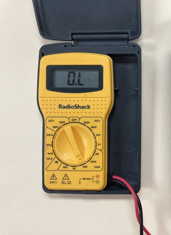 My regular RadioShack multimeter (Image source: Max Maxfield)
 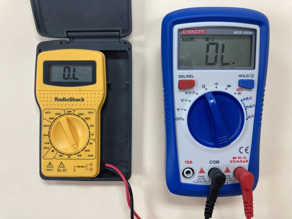 Two low-cost digital multimeters: a regular unit (left) and an auto-ranging unit (right) (Image source: Max Maxfield)
 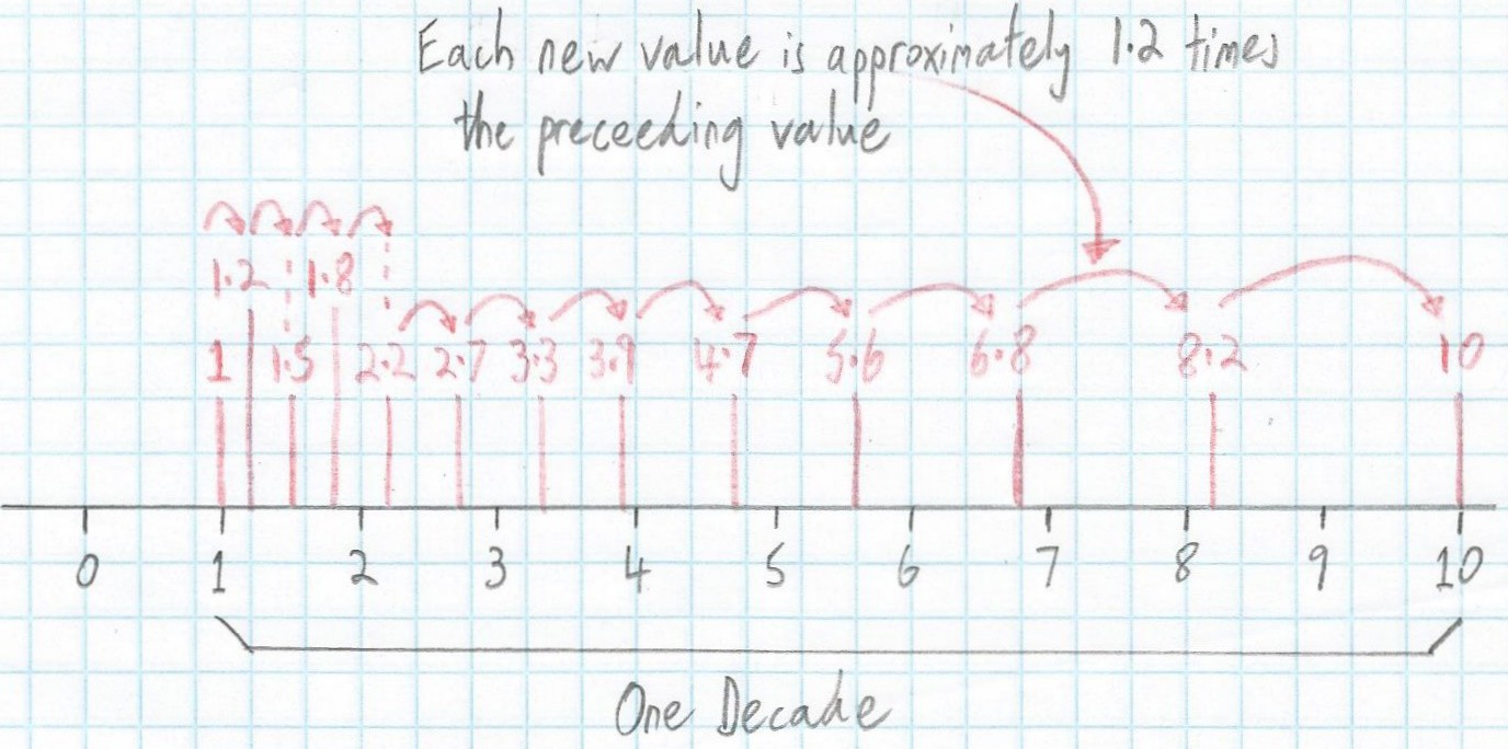 A graphical representation of the E12 scale (Image source: Max Maxfield)
 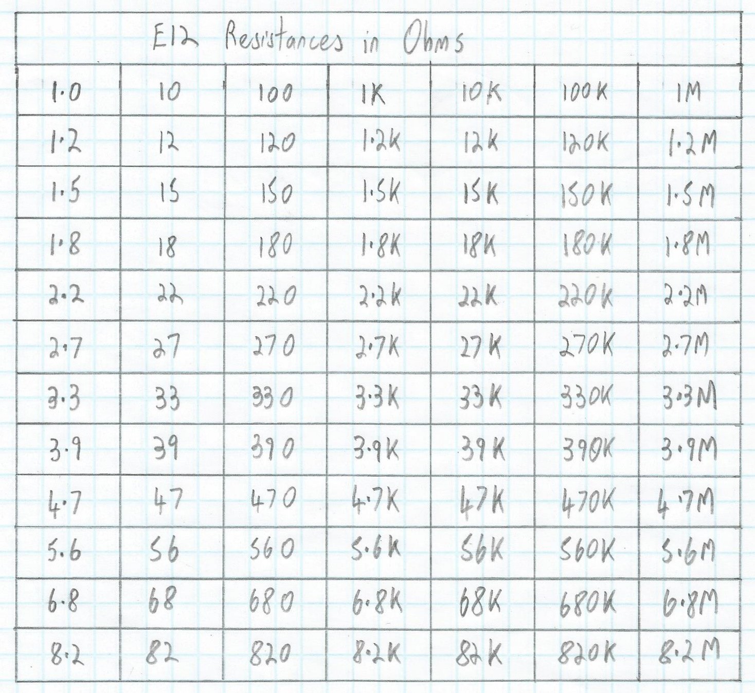 A tabular representation of E12 resistor values (Image source: Max Maxfield)
  It's hard to compare things if you don’t first set the ground rules (Image source: Max Maxfield)
  It’s important to establish a common frame of reference (Image source: Max Maxfield)
 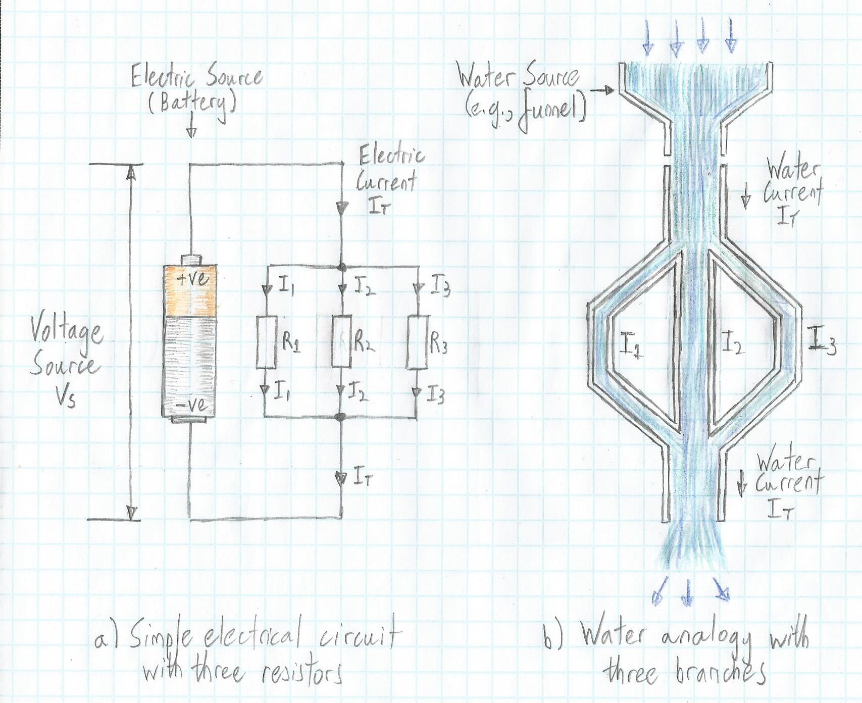 Water analogy of a parallel resistor circuit (Image source: Max Maxfield)
 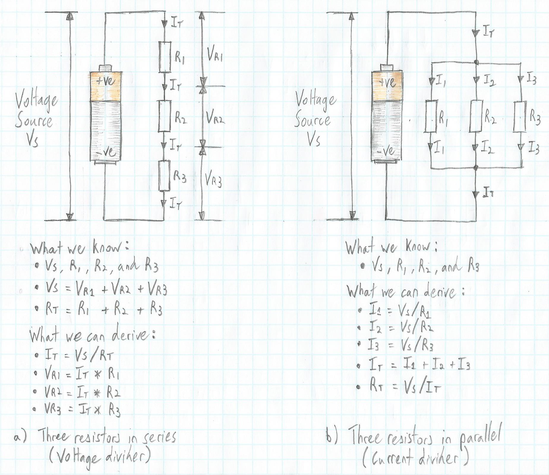 Comparison of circuits with three resistors in series and in parallel (Image source: Max Maxfield)
  Two resistors connected in series (Image source: Max Maxfield)
 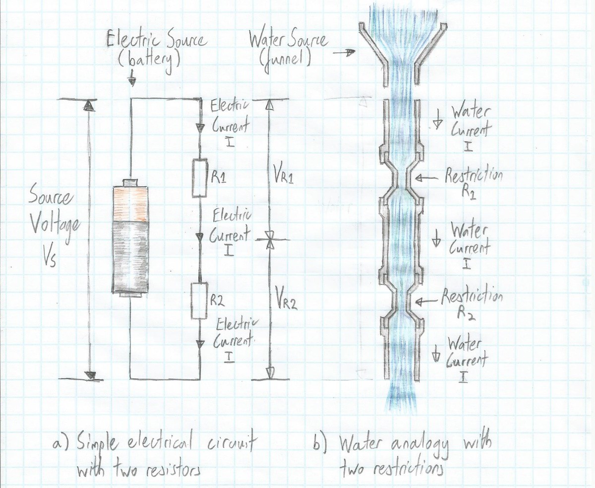 A water analogy for two resistors connected in series (Image source: Max Maxfield)
 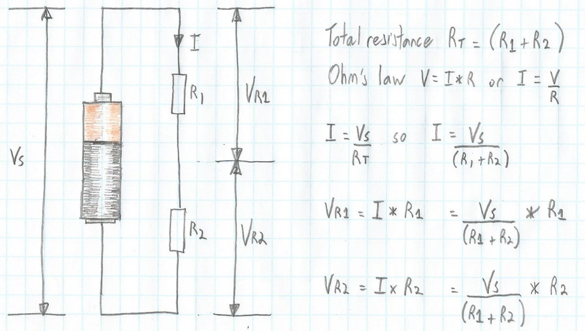 Voltage calculations for two resistors connected in series (Image source: Max Maxfield)
 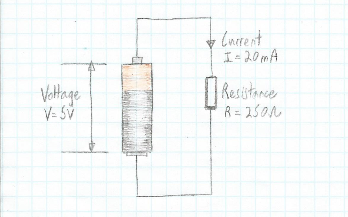 A simple circuit comprising a battery, a resistor, and two pieces of wire (Image source: Max Maxfield)
  The P, V, I, R circle (Image source: Max Maxfield)
 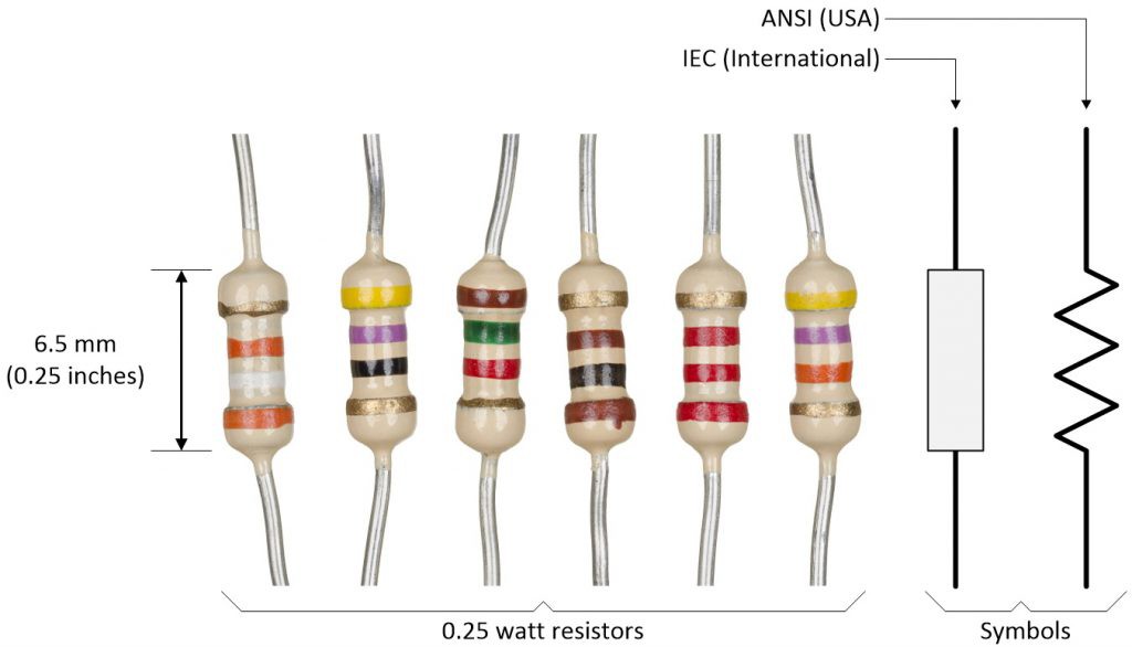 Some 0.25 watt resistors and alternative symbols (Image source: Max Maxfield)
 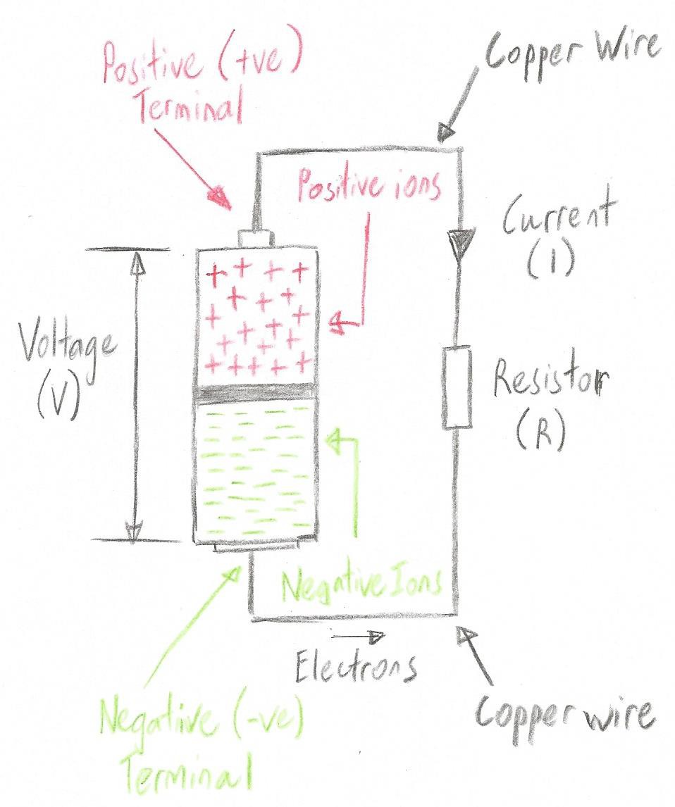 A simple circuit comprising a battery and a resistor (Image source: Max Maxfield)
  A water analogy of voltage (V), current (I), and resistance (R) (Image source: Max Maxfield)
 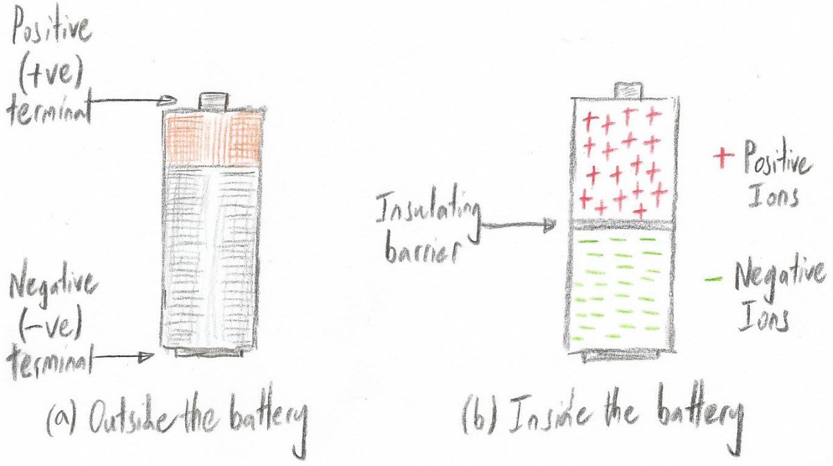 Peering inside a simple battery (Image source: Max Maxfield)
 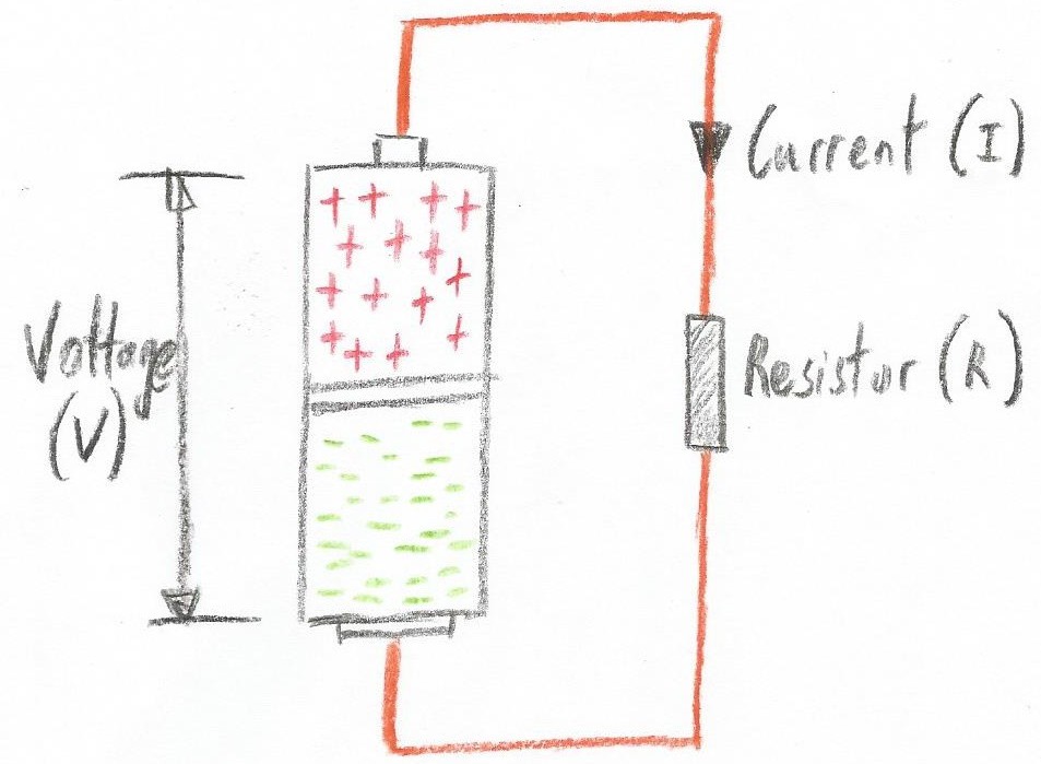 A simple circuit (Image source: Max Maxfield)
 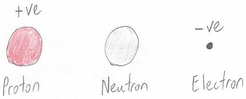 Protons, neutrons, and electrons (Image source: Max Maxfield)
 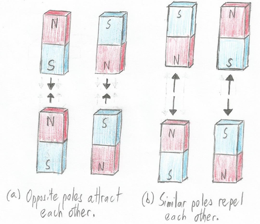 Magnets can both attract and repel each other (Image source: Max Maxfield)
 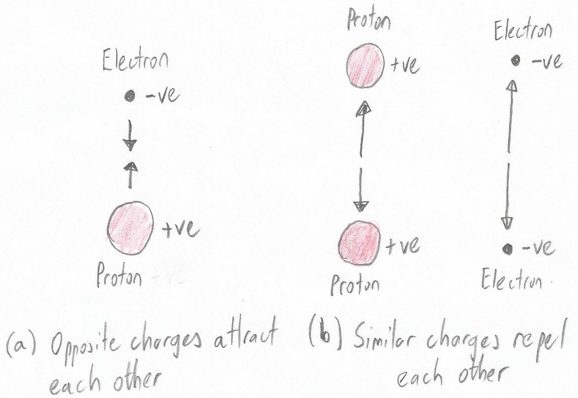 Protons and electrons are attracted to each other (Image source: Max Maxfield)
 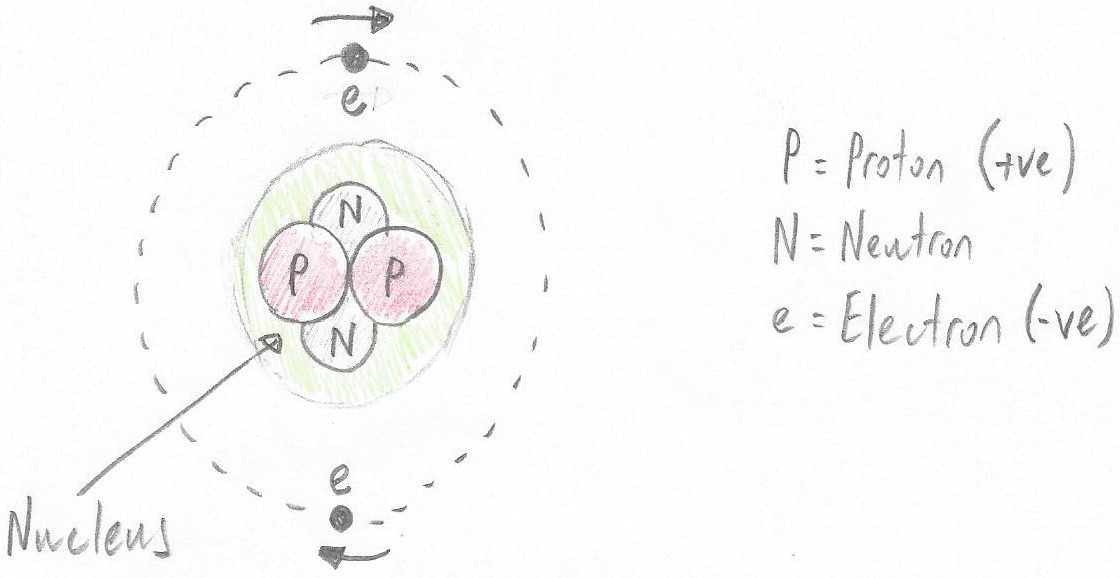 An example atom formed from two protons, two neutrons, and two electrons (note that the green area doesn’t really exist; it's only shown here to indicate the nucleus) (Image source: Max Maxfield)
  The Cool Beans sporting their voltage (V), current (I), and resistance (R) T-shirts (Image source: Max Maxfield)
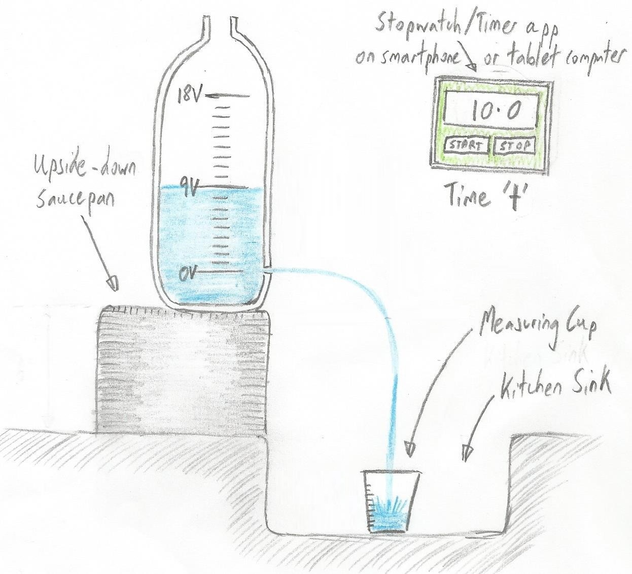 Representing voltage, current, and resistance with a water analogy (Image source: Max Maxfield)
 We can think of voltage (V) as pushing current (I) while resistance (R) does its best to impede things (Image source: Max Maxfield)
 I’m the Cool Bean on the right (the good looking one in the Hawaiian shirt)
