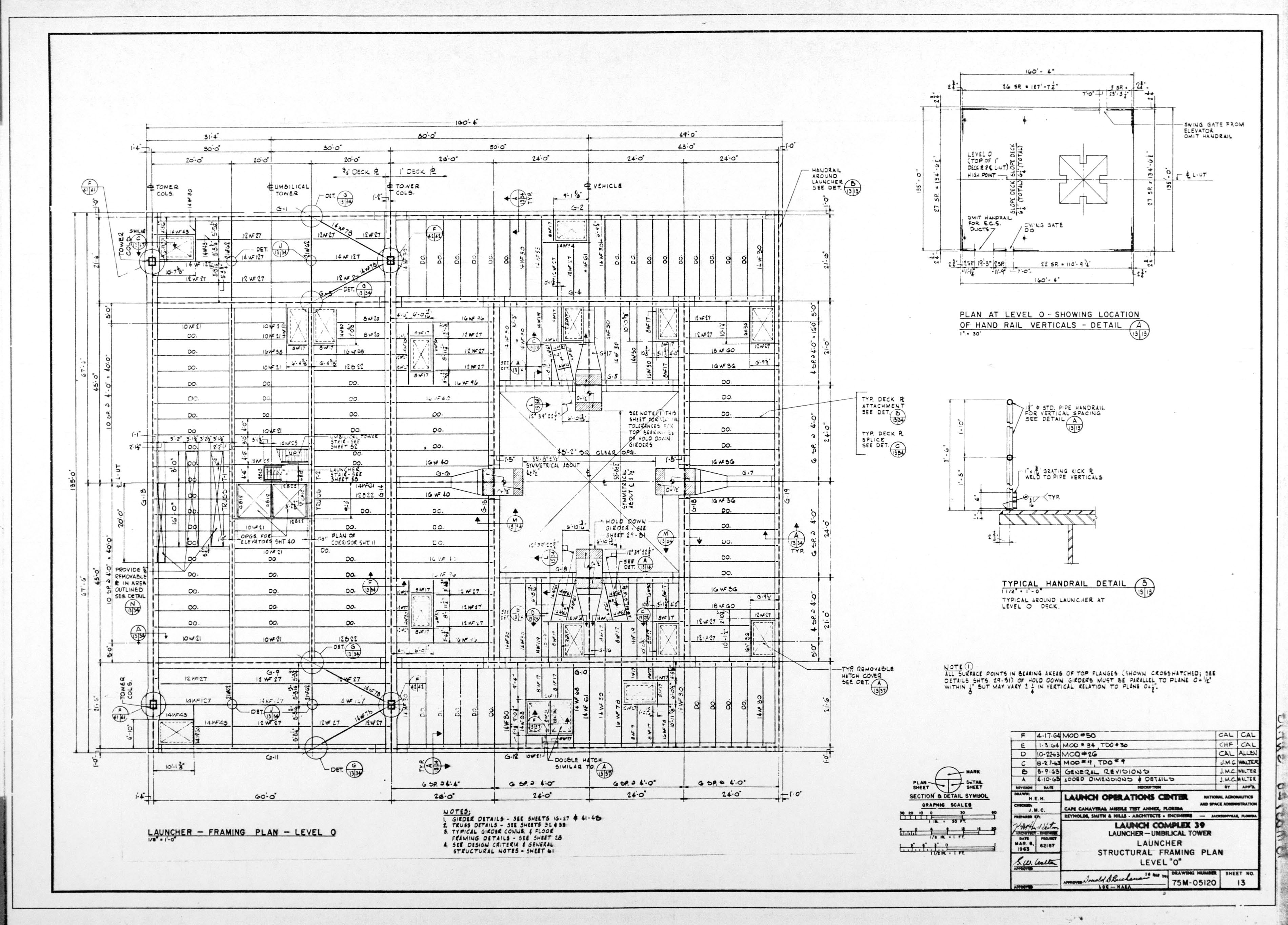
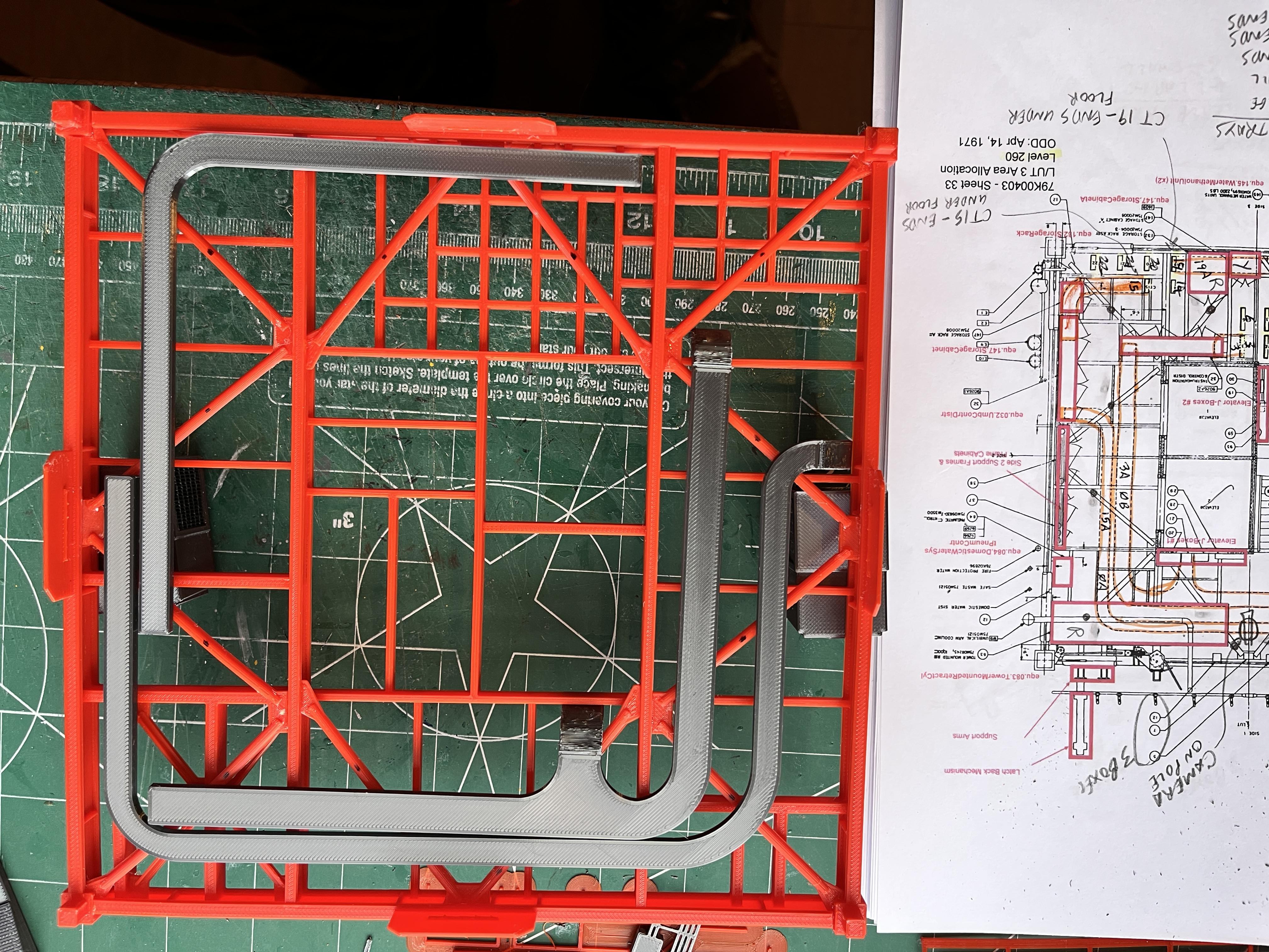
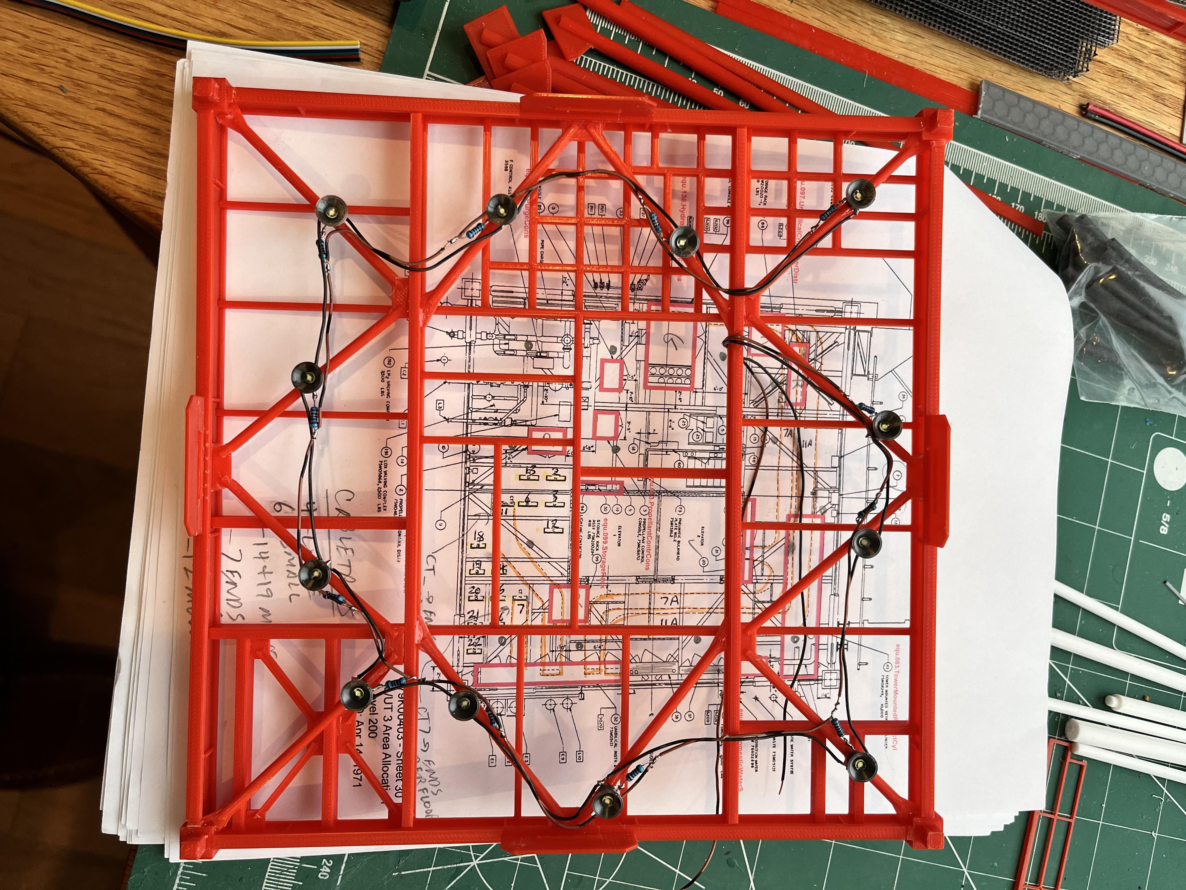
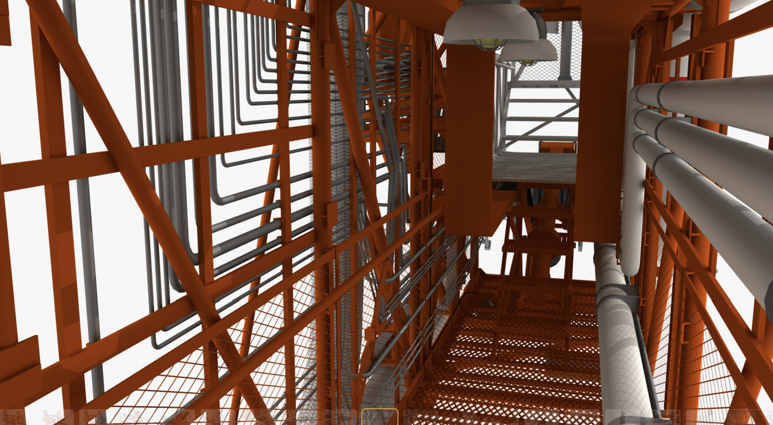
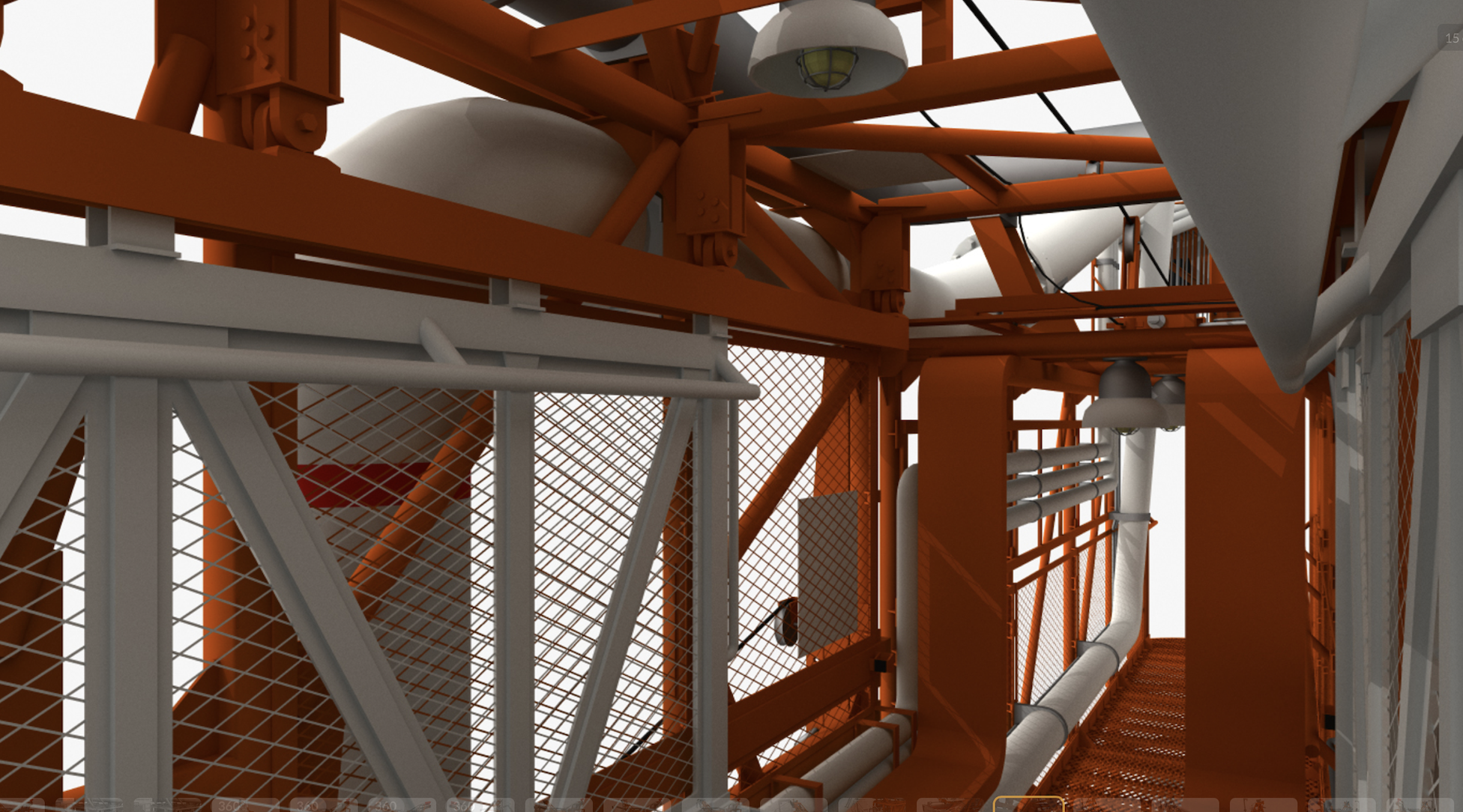
You should start by gathering information about the model. There is no detailed step by step assembly instructions as that would take years and be thousands of pages. Start by joining the LUT Group at https://groups.io/g/LUTGroup. Go in and download as much information as you can. The two most important documents are 75M-05120 and 75M-05121. These are original NASA documents used to build the LUT. The MicroArtwork is an invaluable resource. The other important documents are the floor plans showing where all the equipment is placed. This is in the CatoLibrary -> LUT Drawings -> 79K-00403 - LUT 3 Area Alloc. Another major resource can be found on the TurboSquid website. Search for Apollo LUT. There are many 3D views that are invaluable.
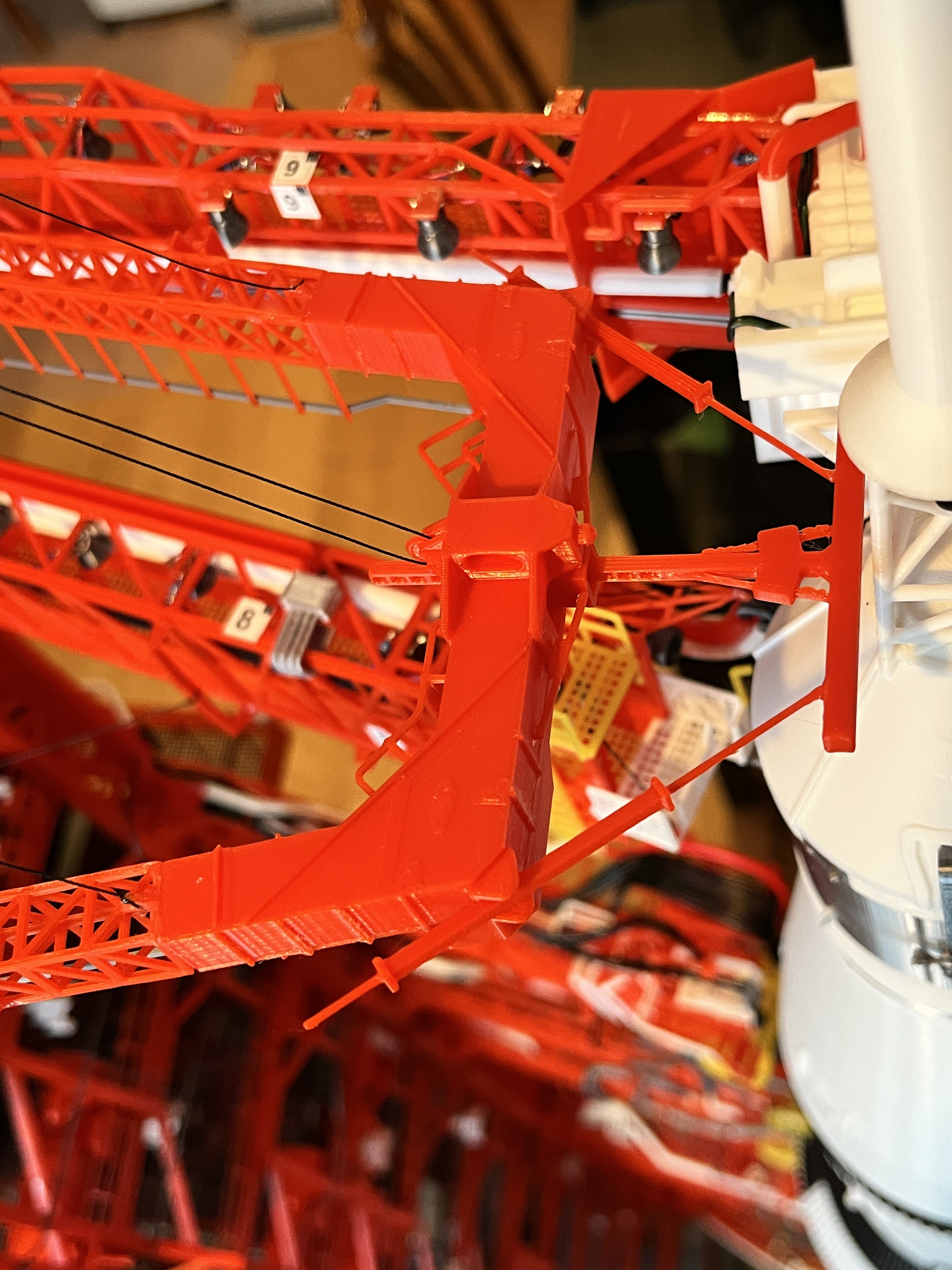
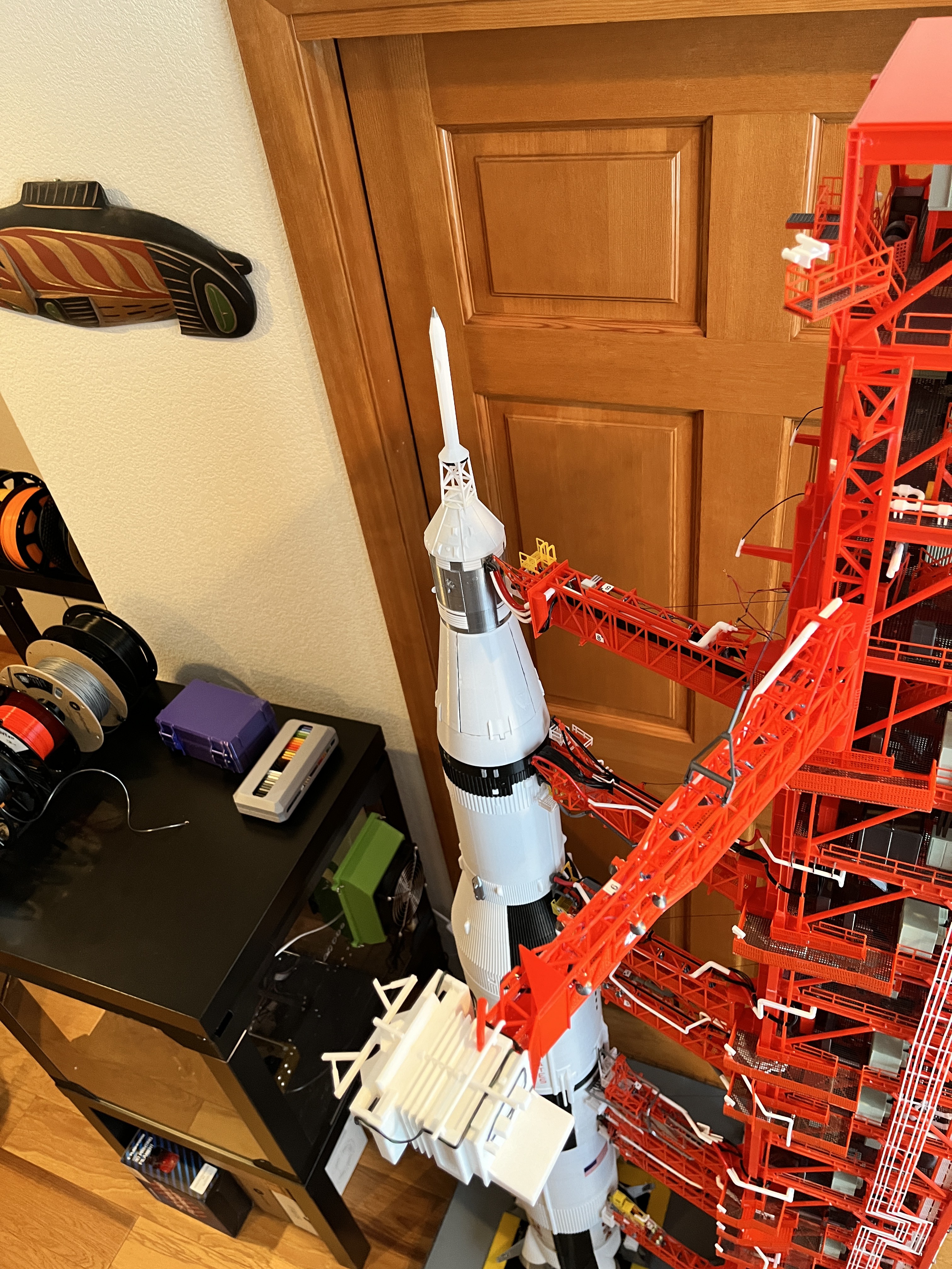
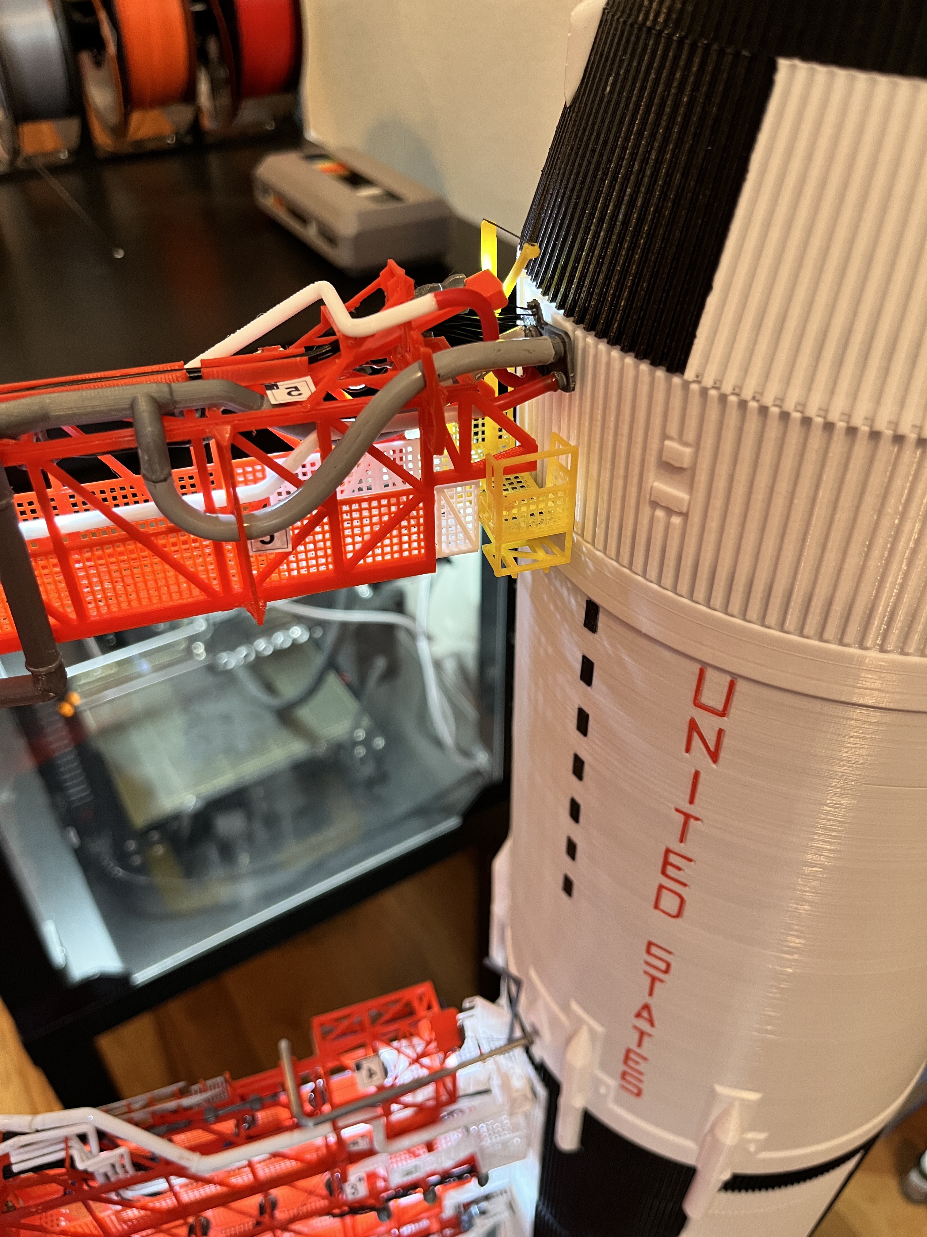
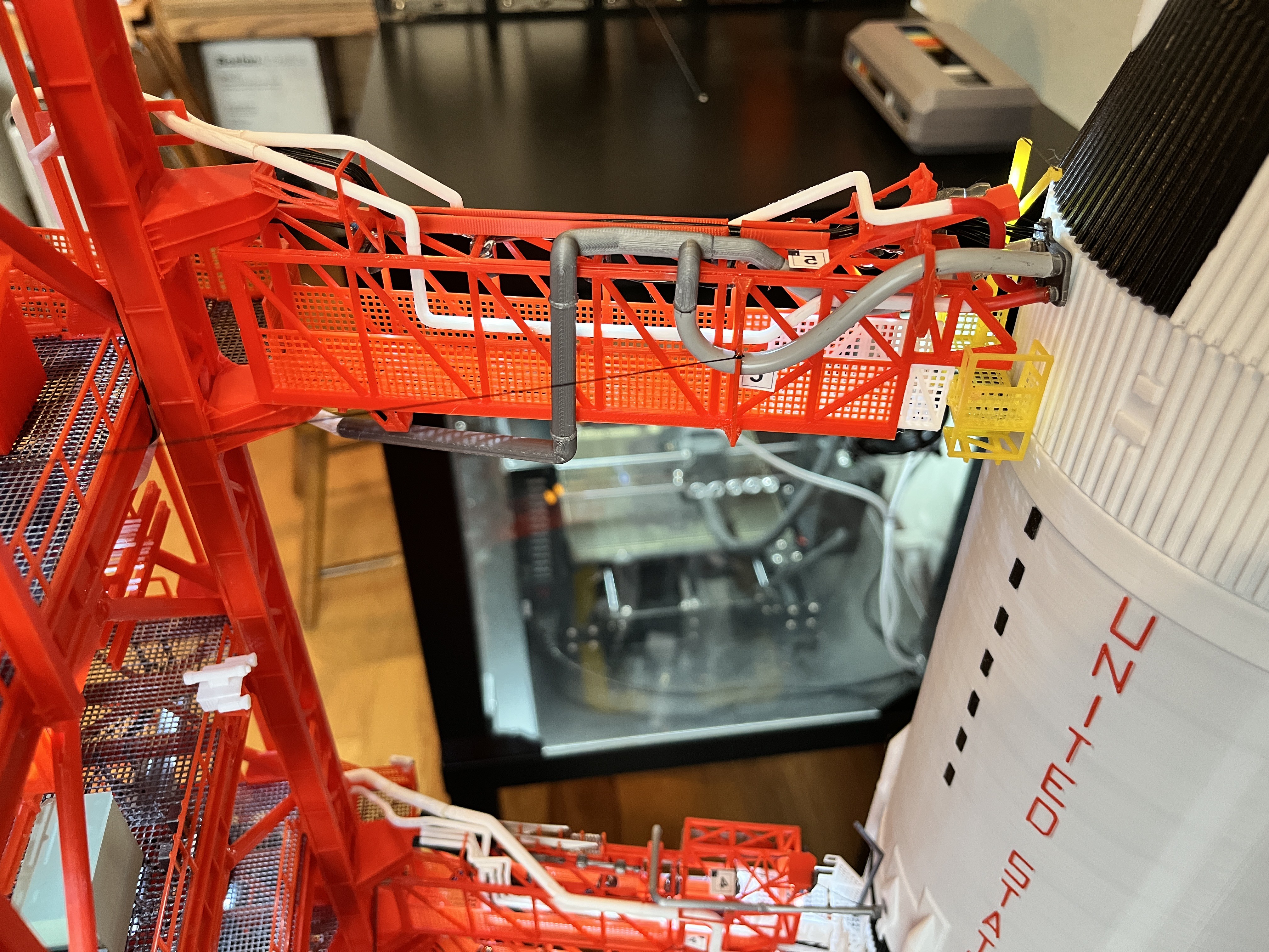
The model you need for the entire model are the Saturn V rocket which can be found at https://www.chronic3d.com/ with the four model parts purchased on https://cults3d.com/en/3d-model/various/apollo-15-saturn-5-pack-1-4-etage-s1c.
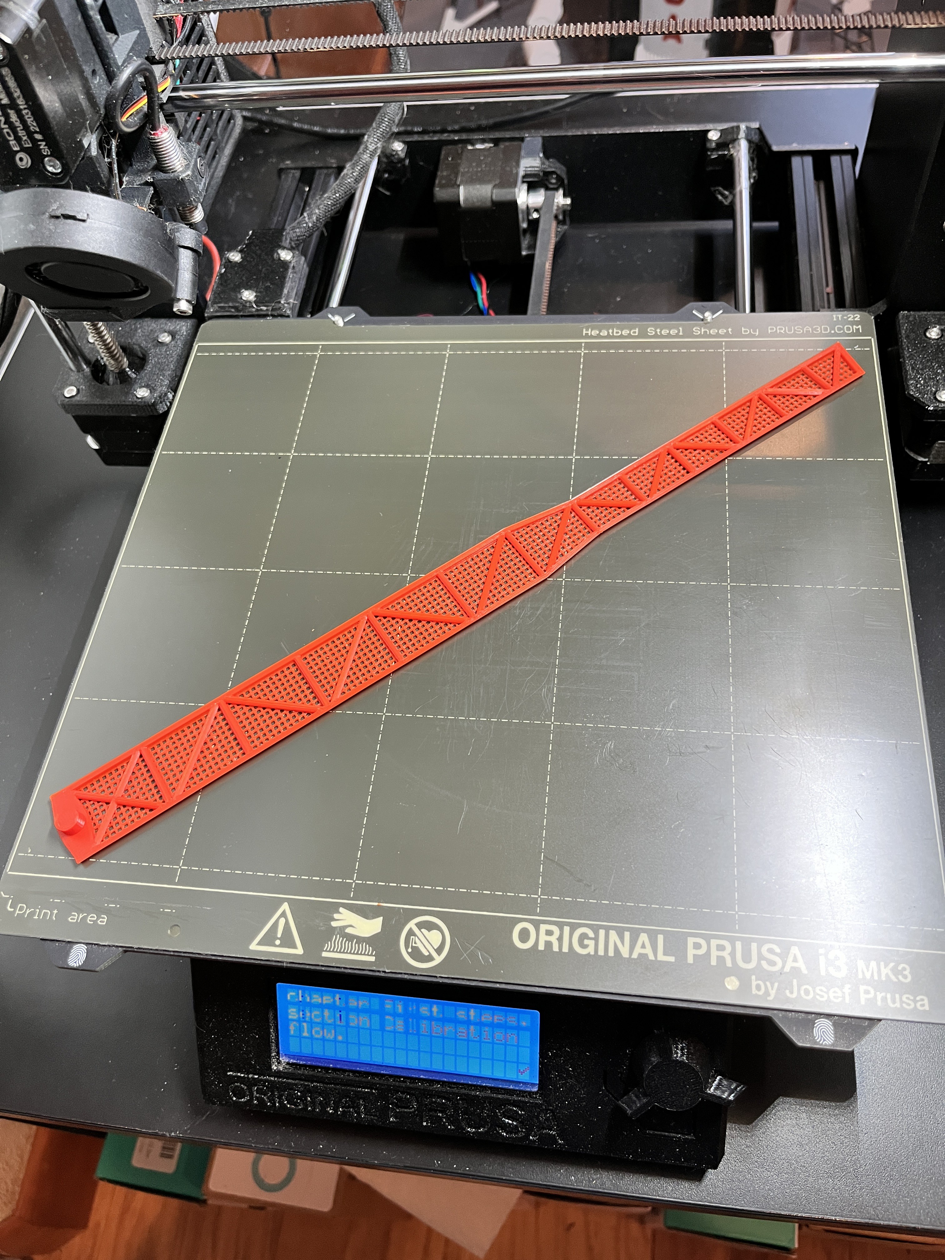
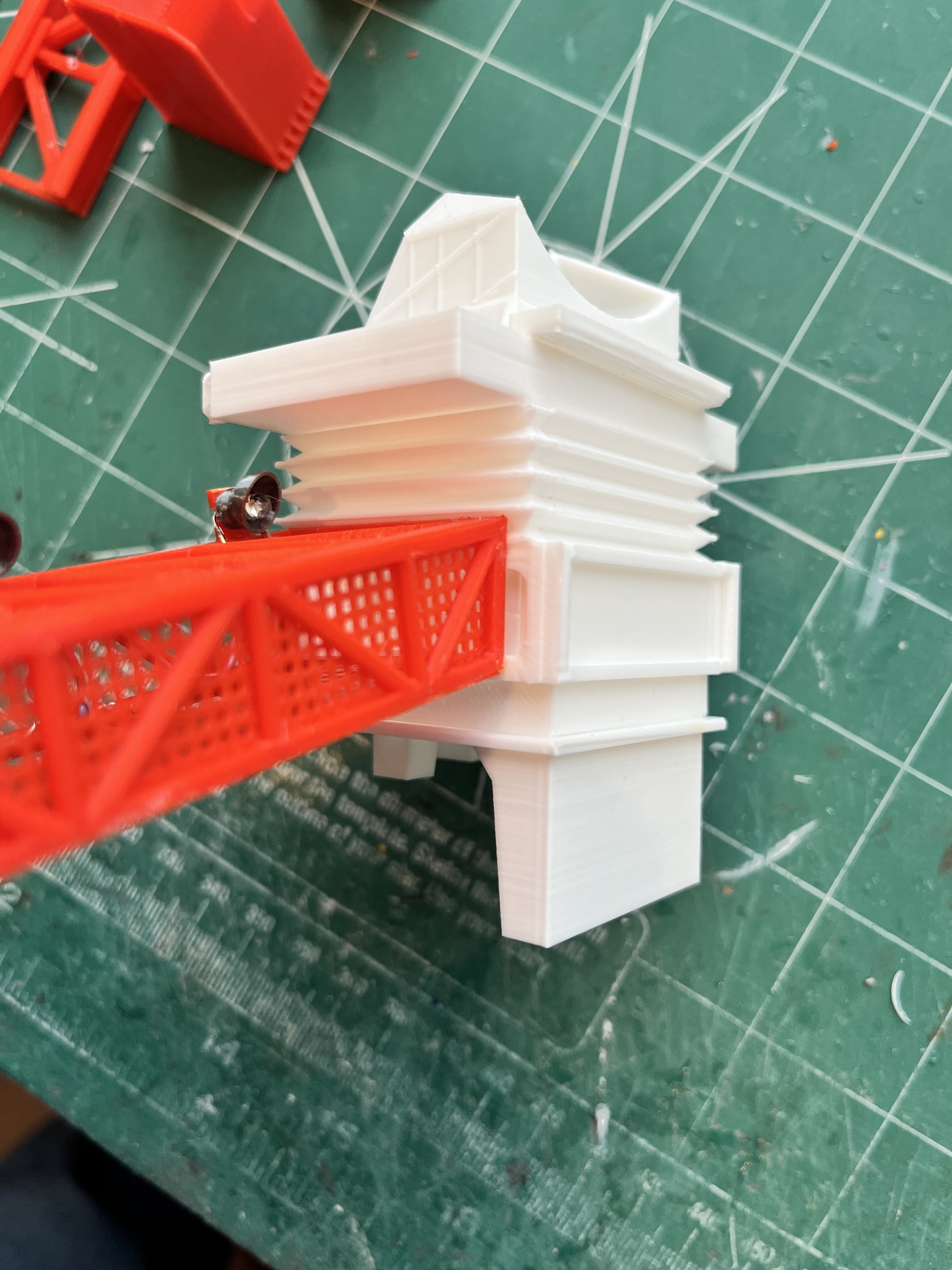
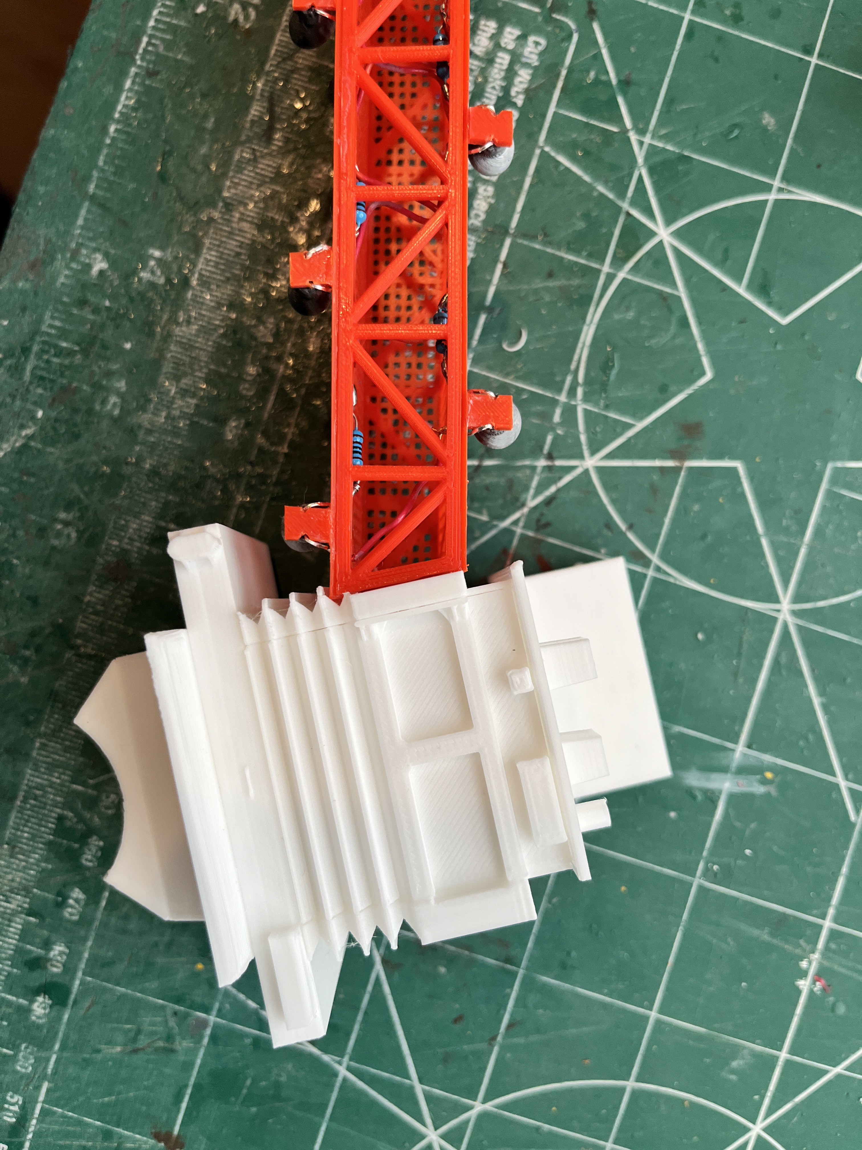
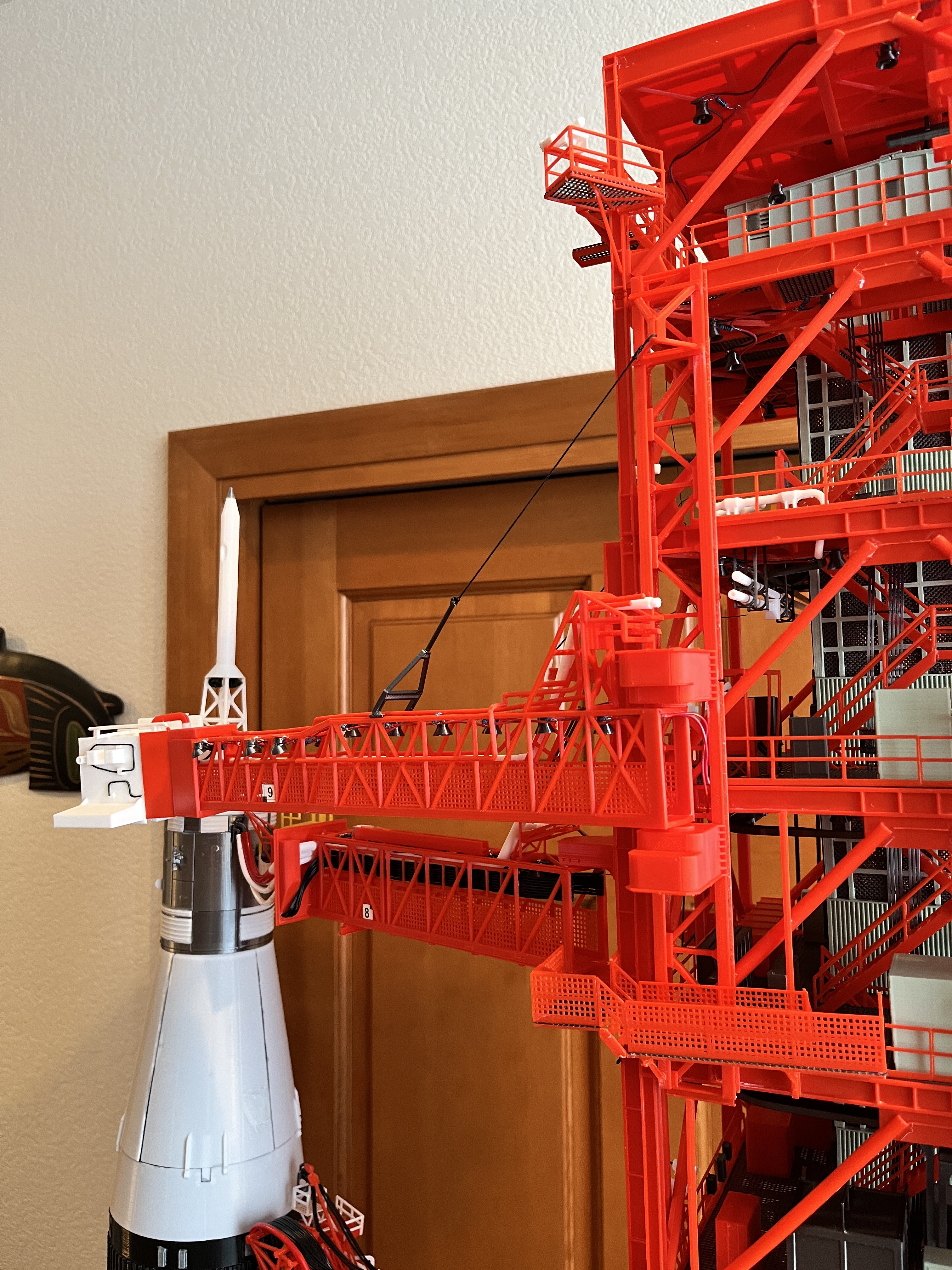
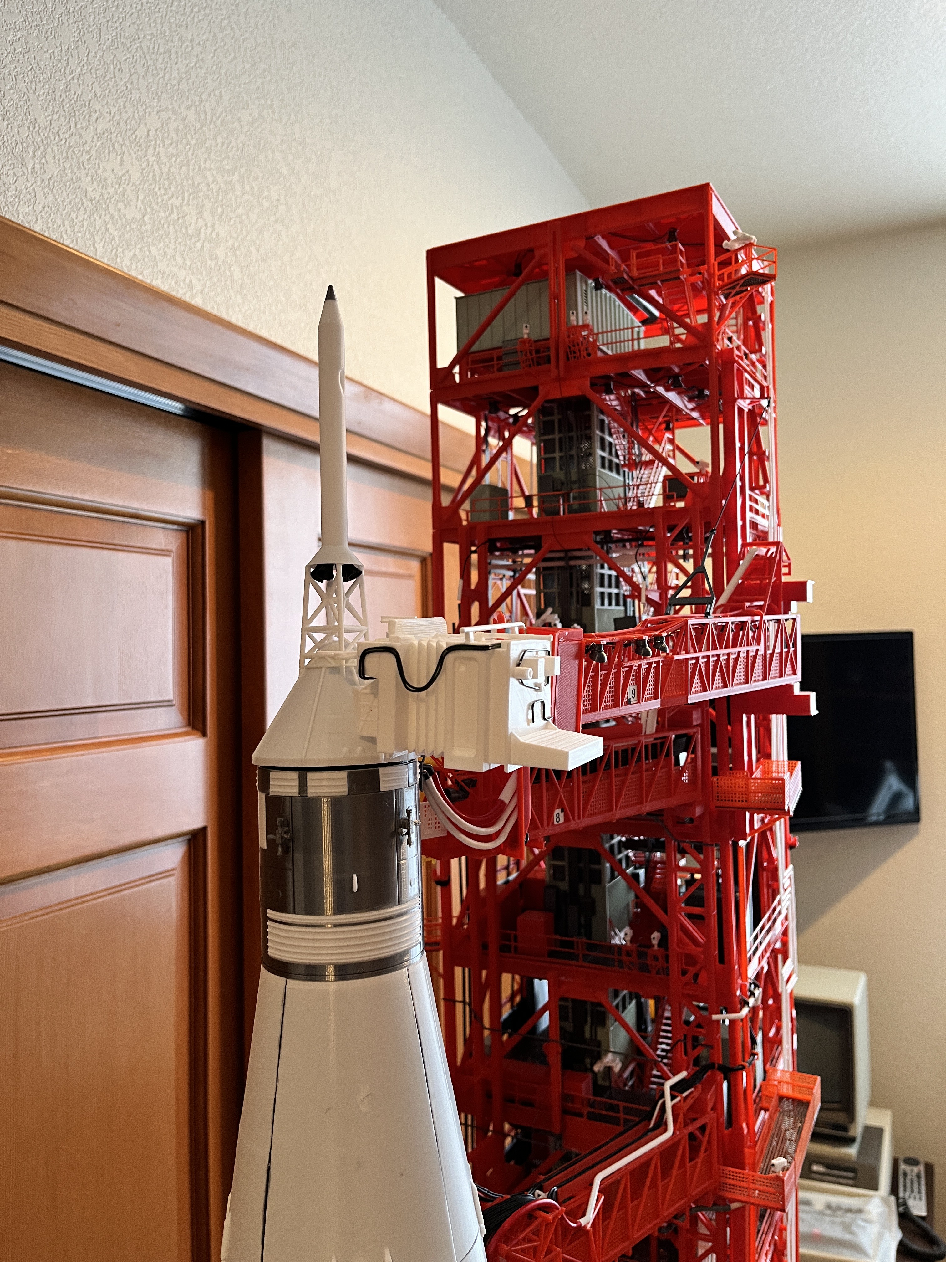
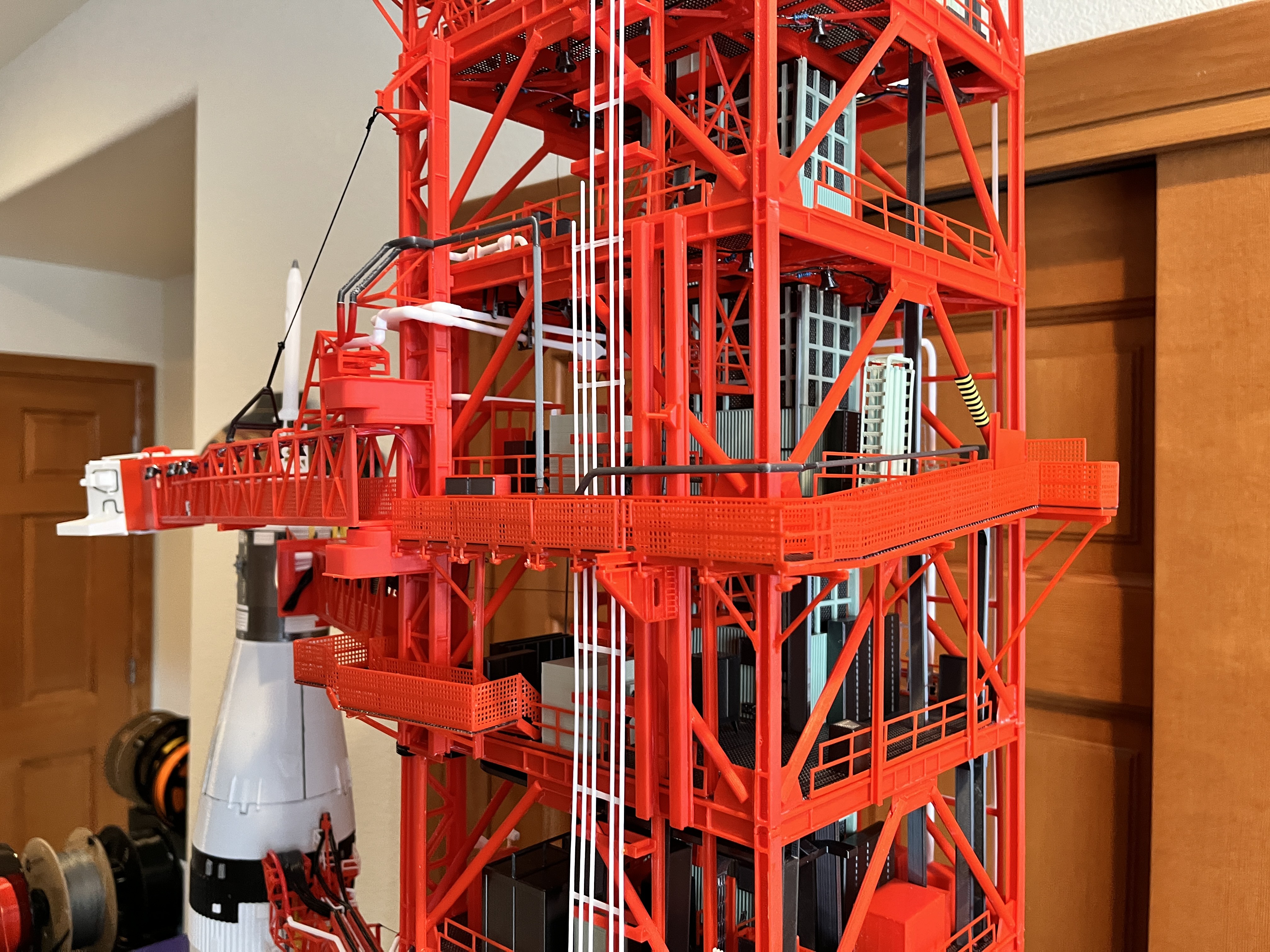
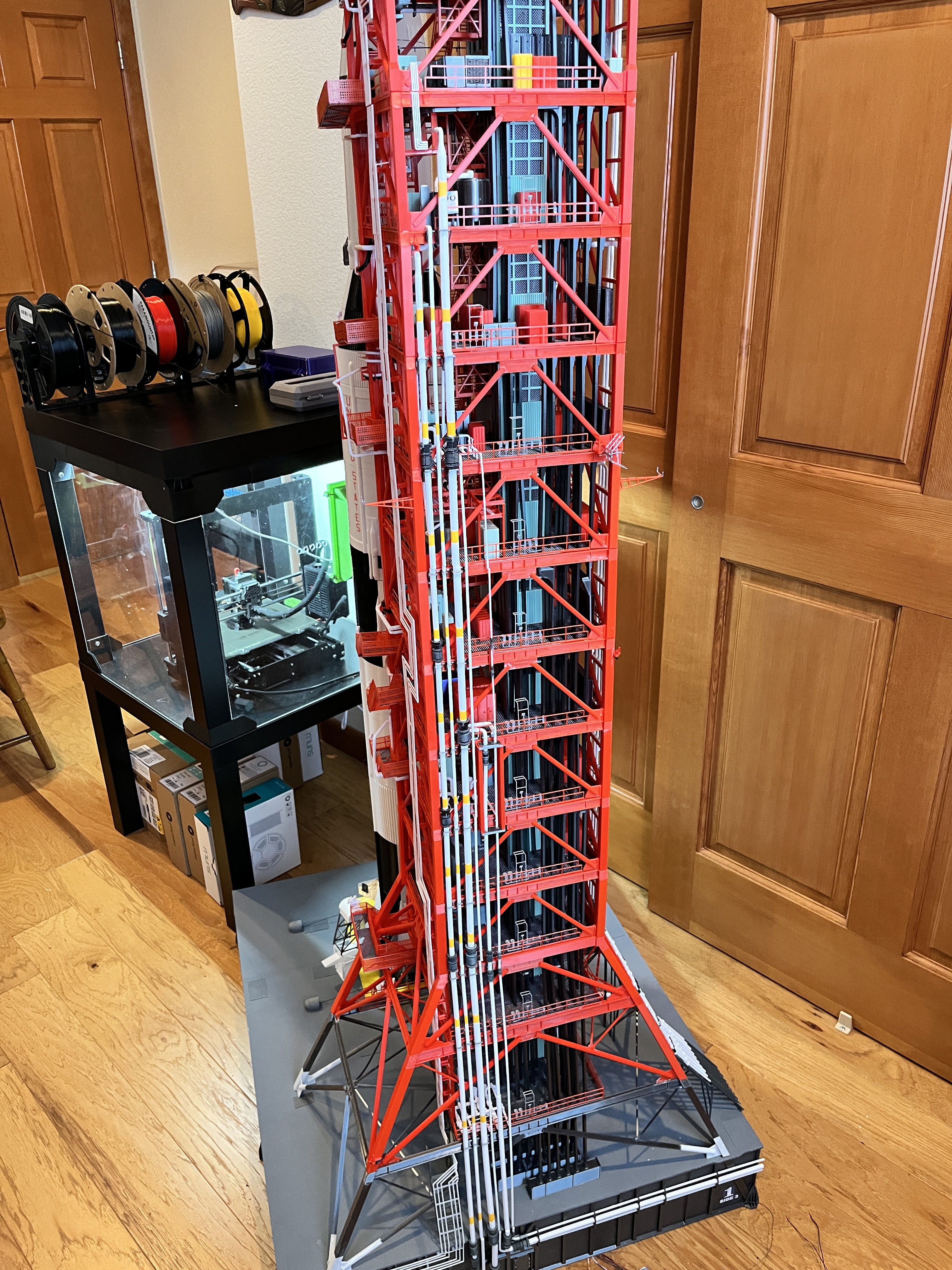
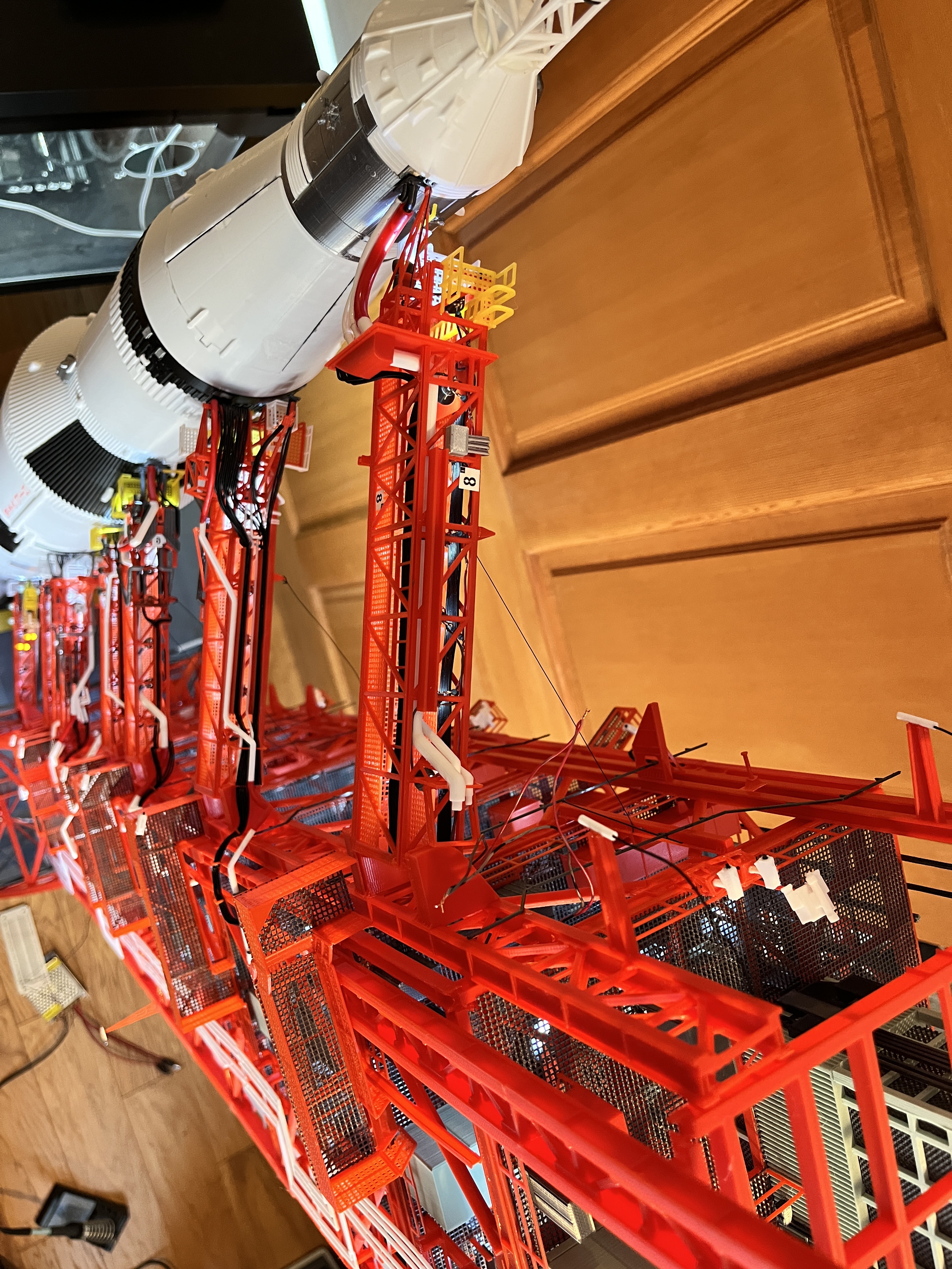
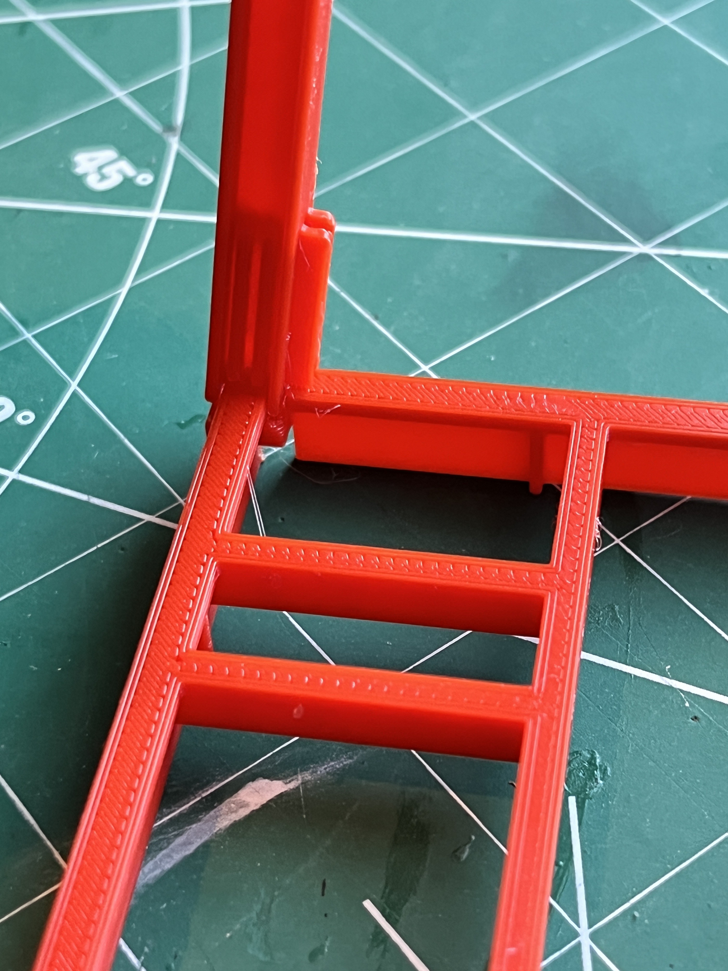
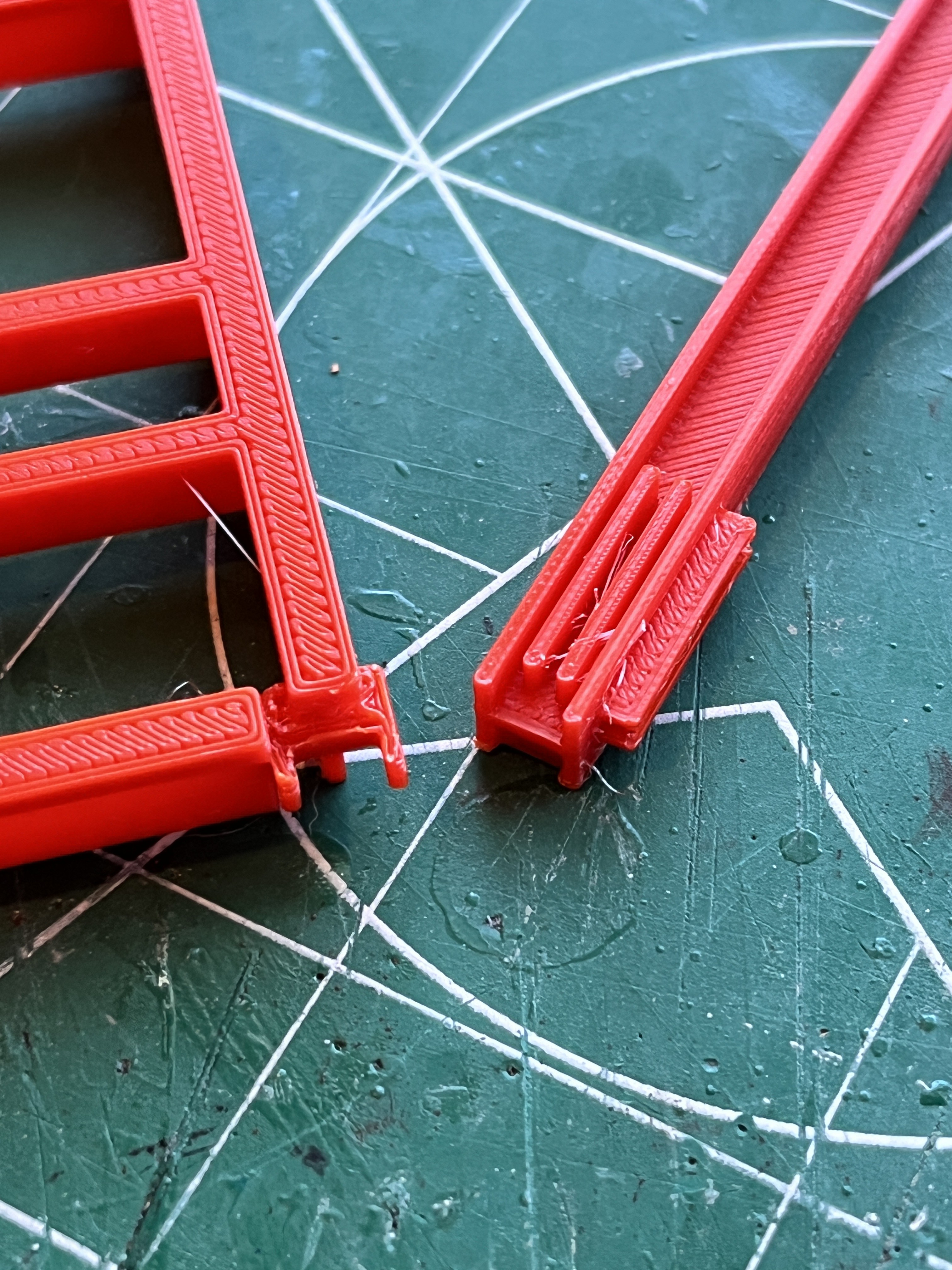
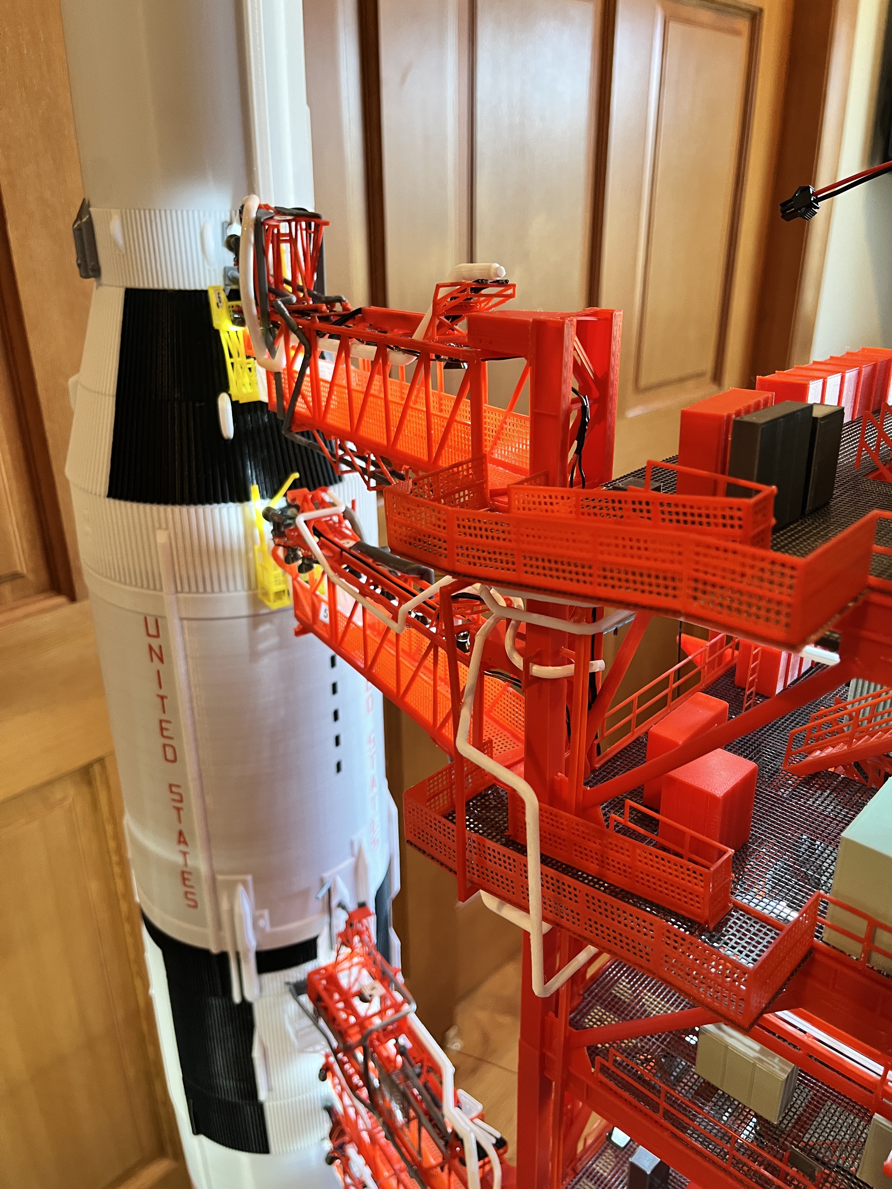
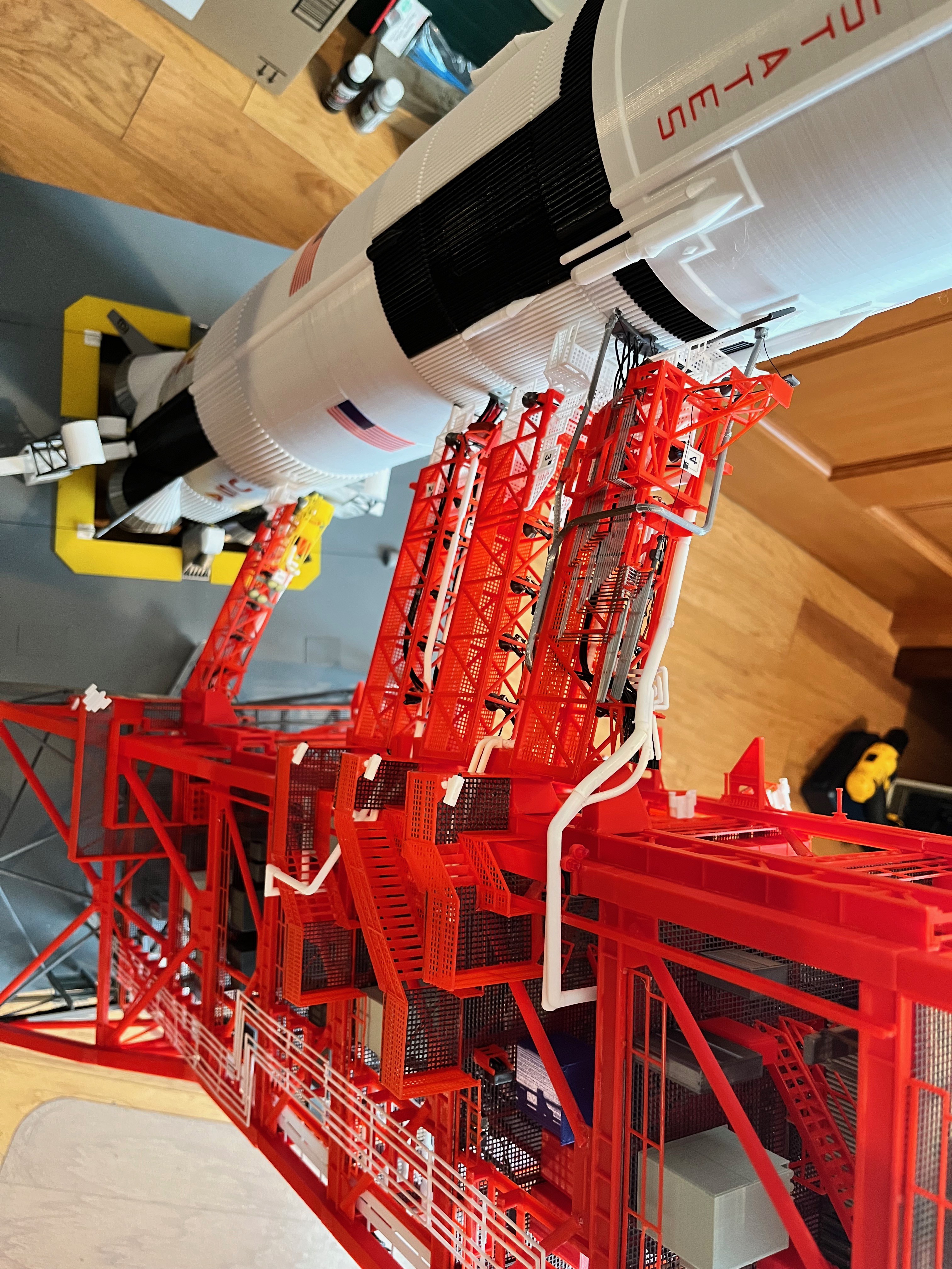
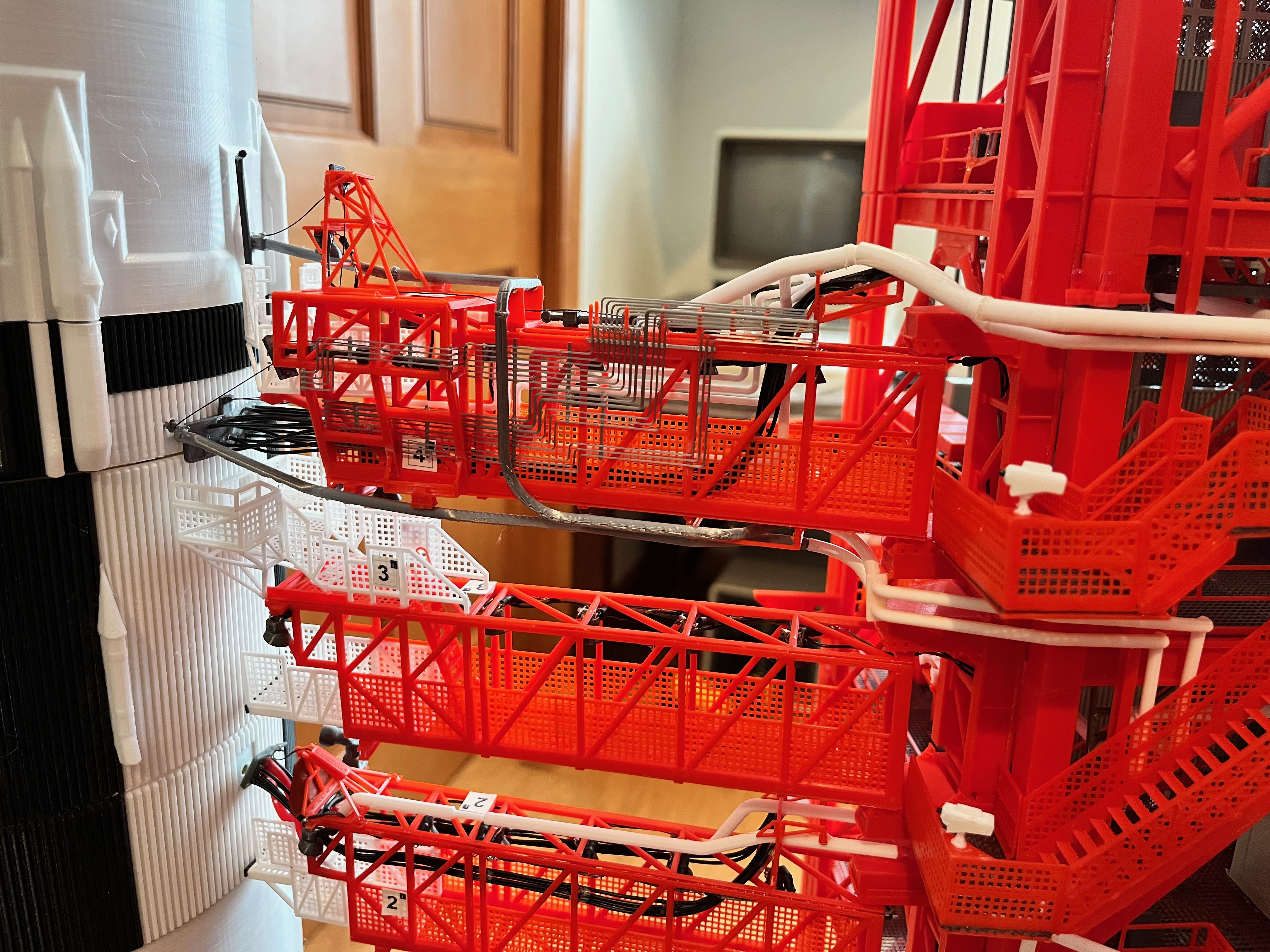
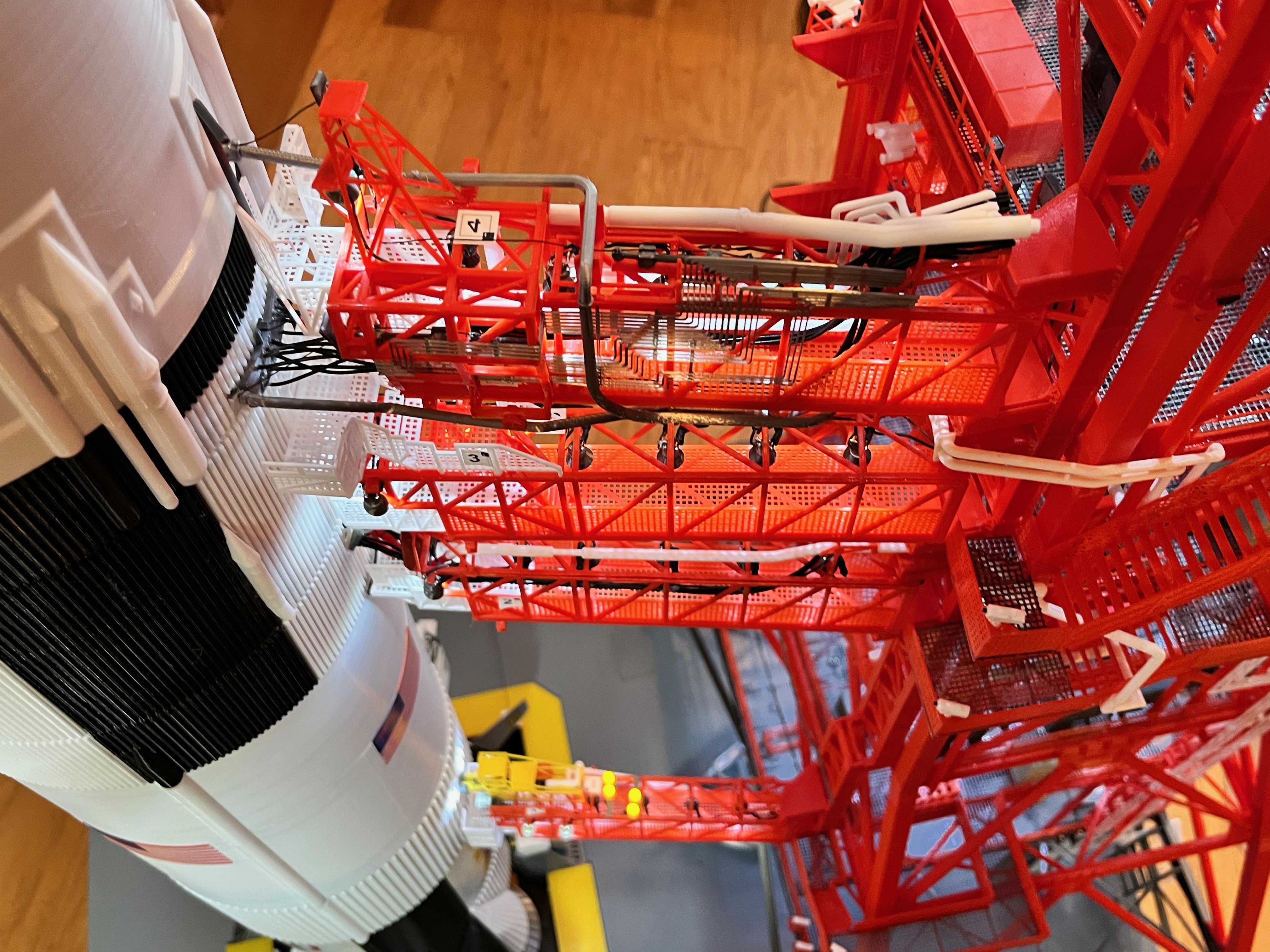
The next part you need is the launcher which can be found at https://www.printables.com/model/621901-apollo-umbilical-tower-new. The launcher is made by skinning a wooden box. There are other various models referenced in the build. This has been a collaborative effort.
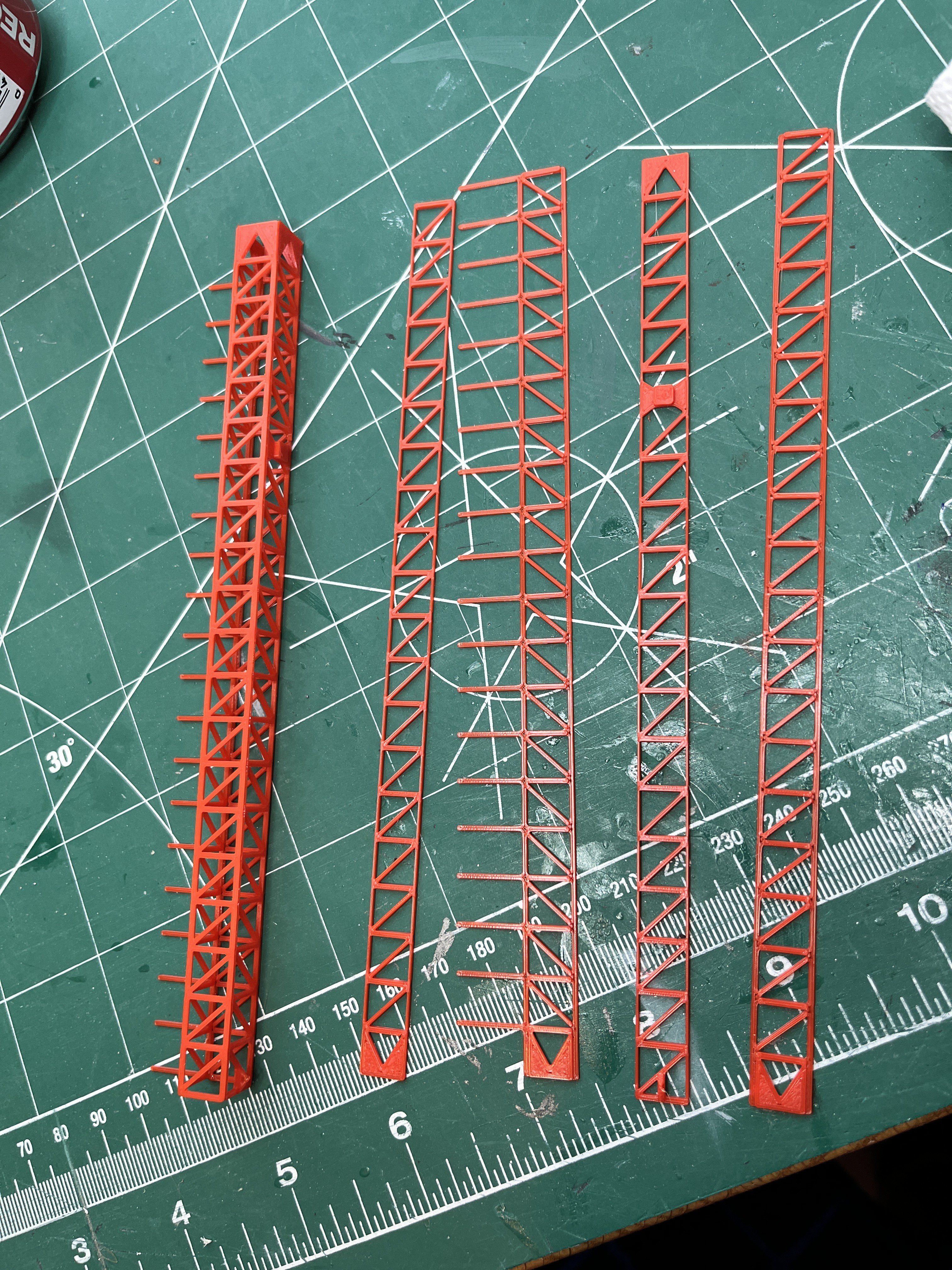
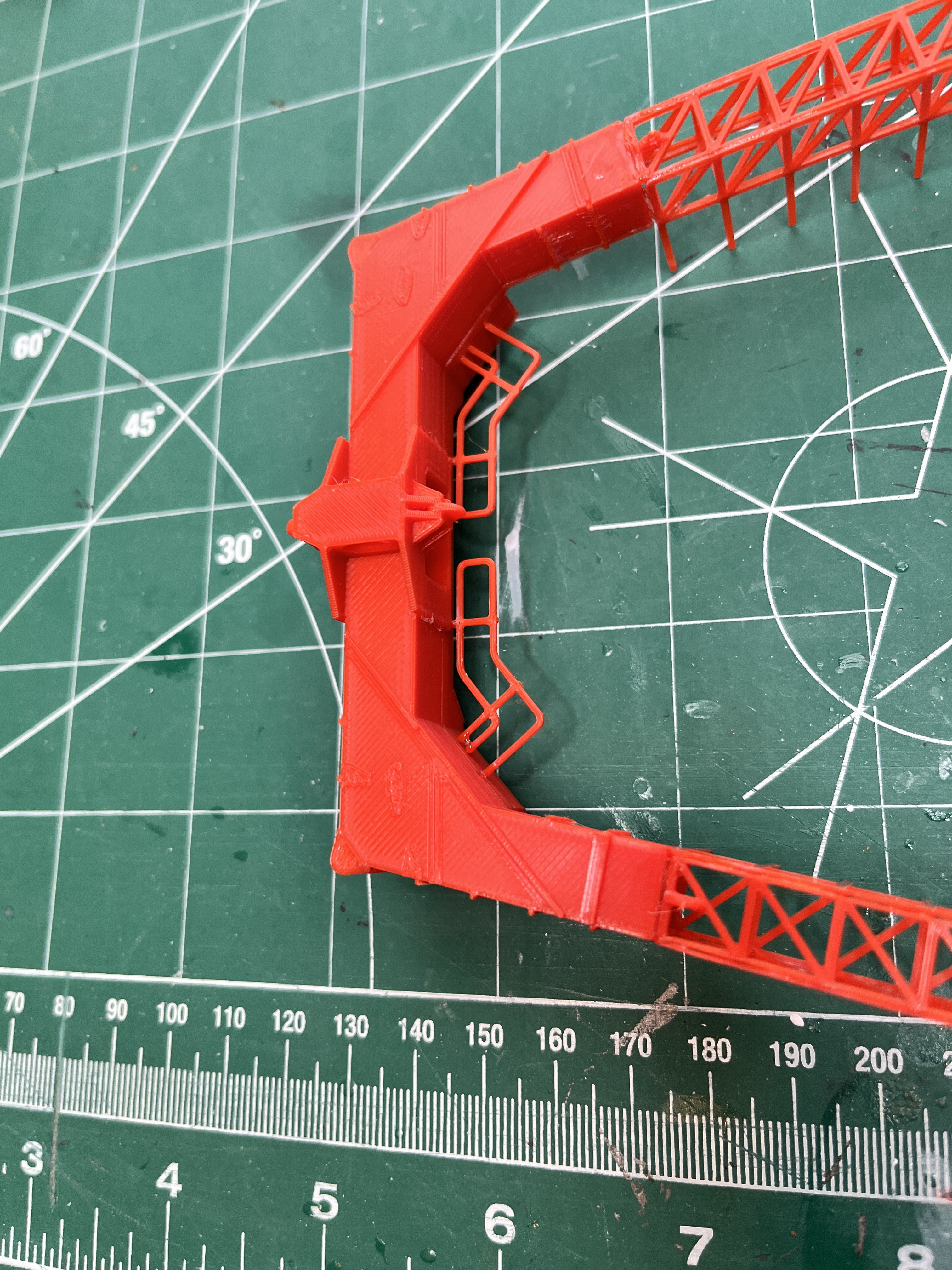
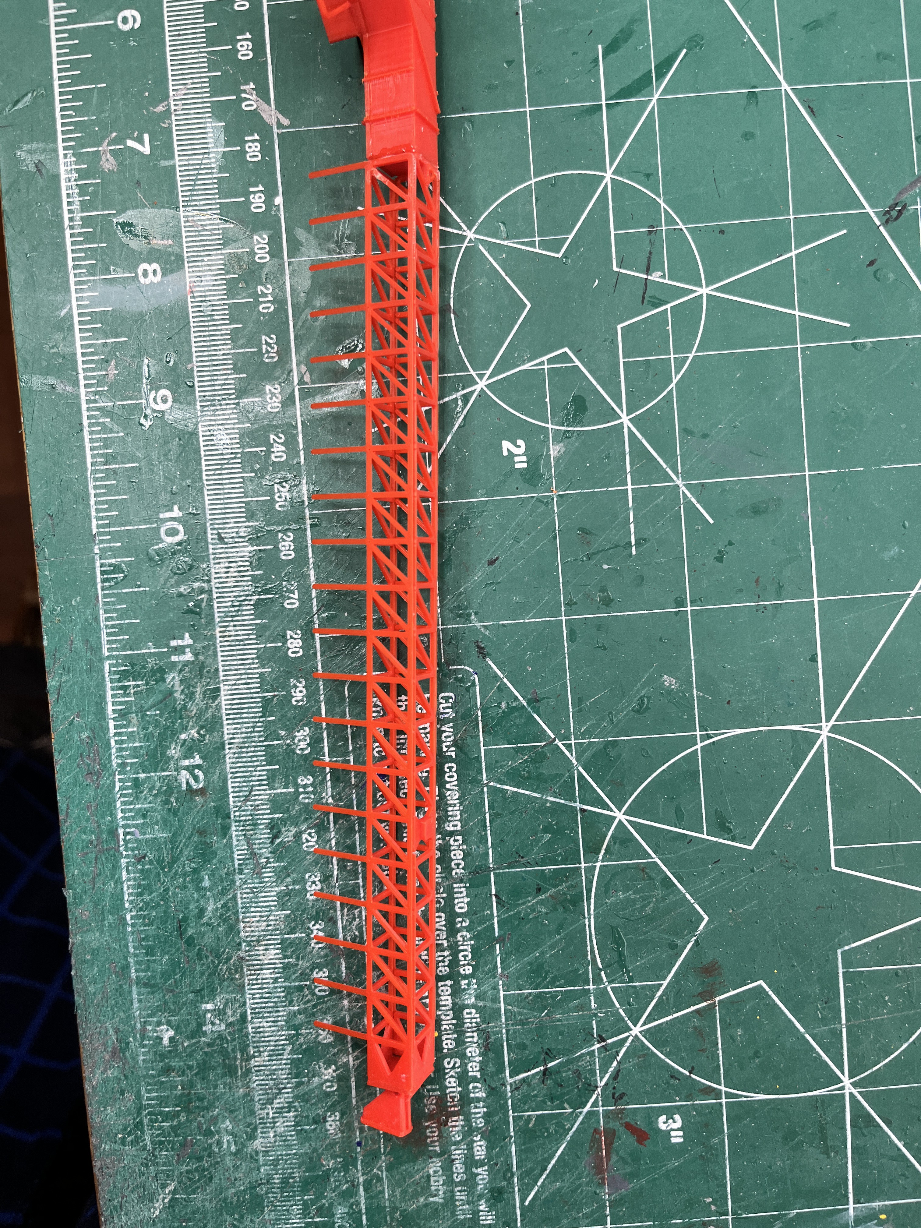
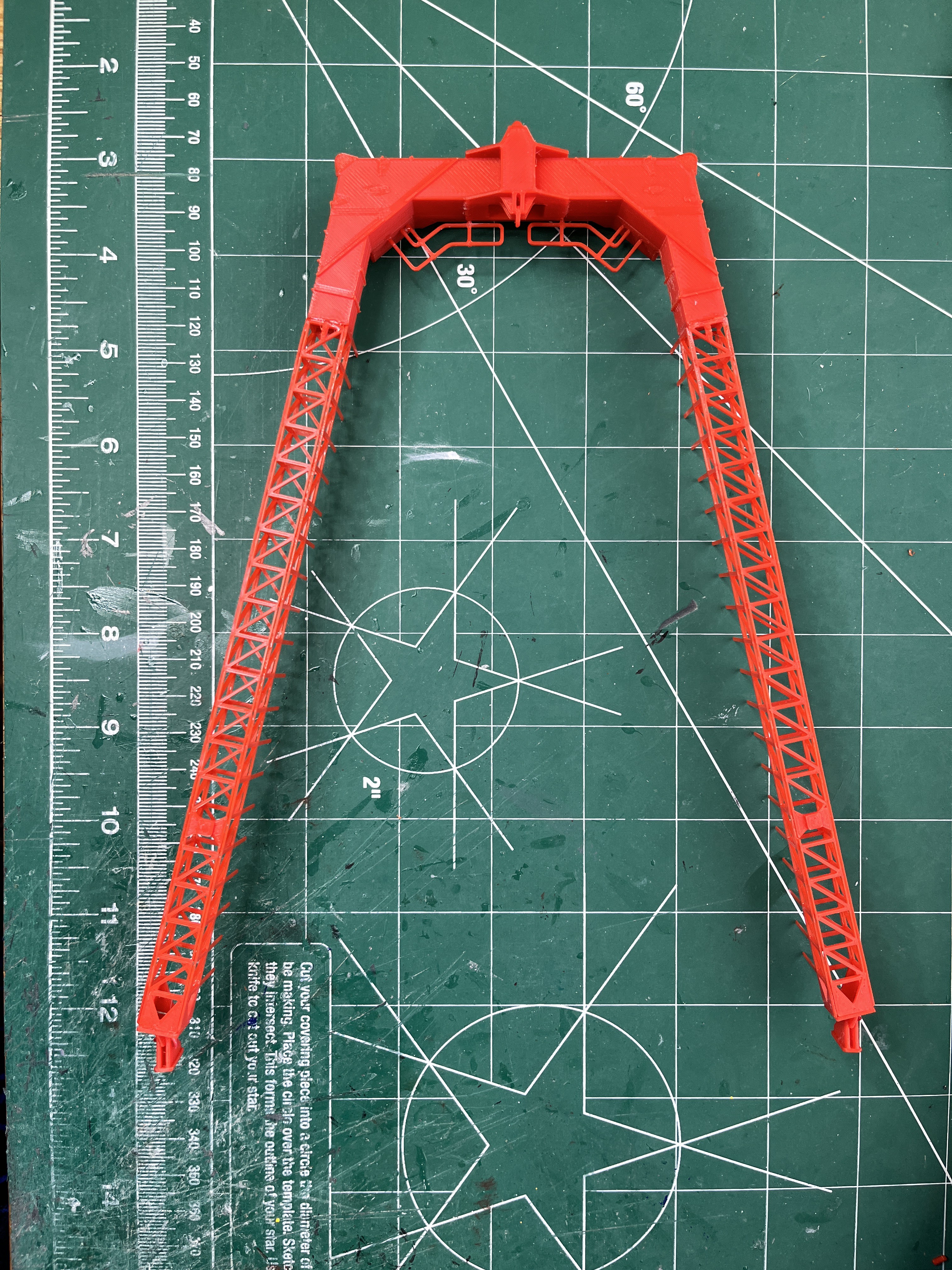
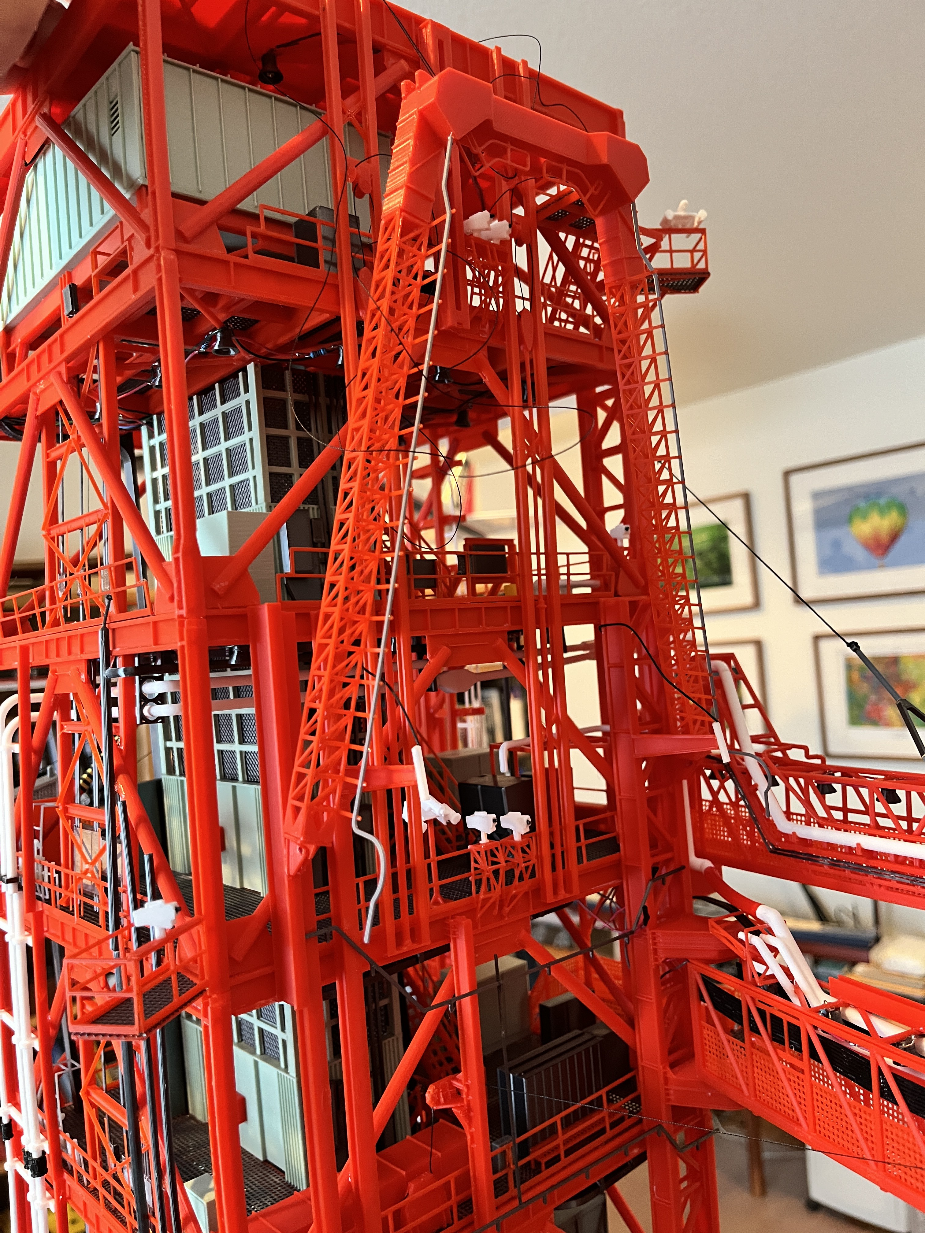
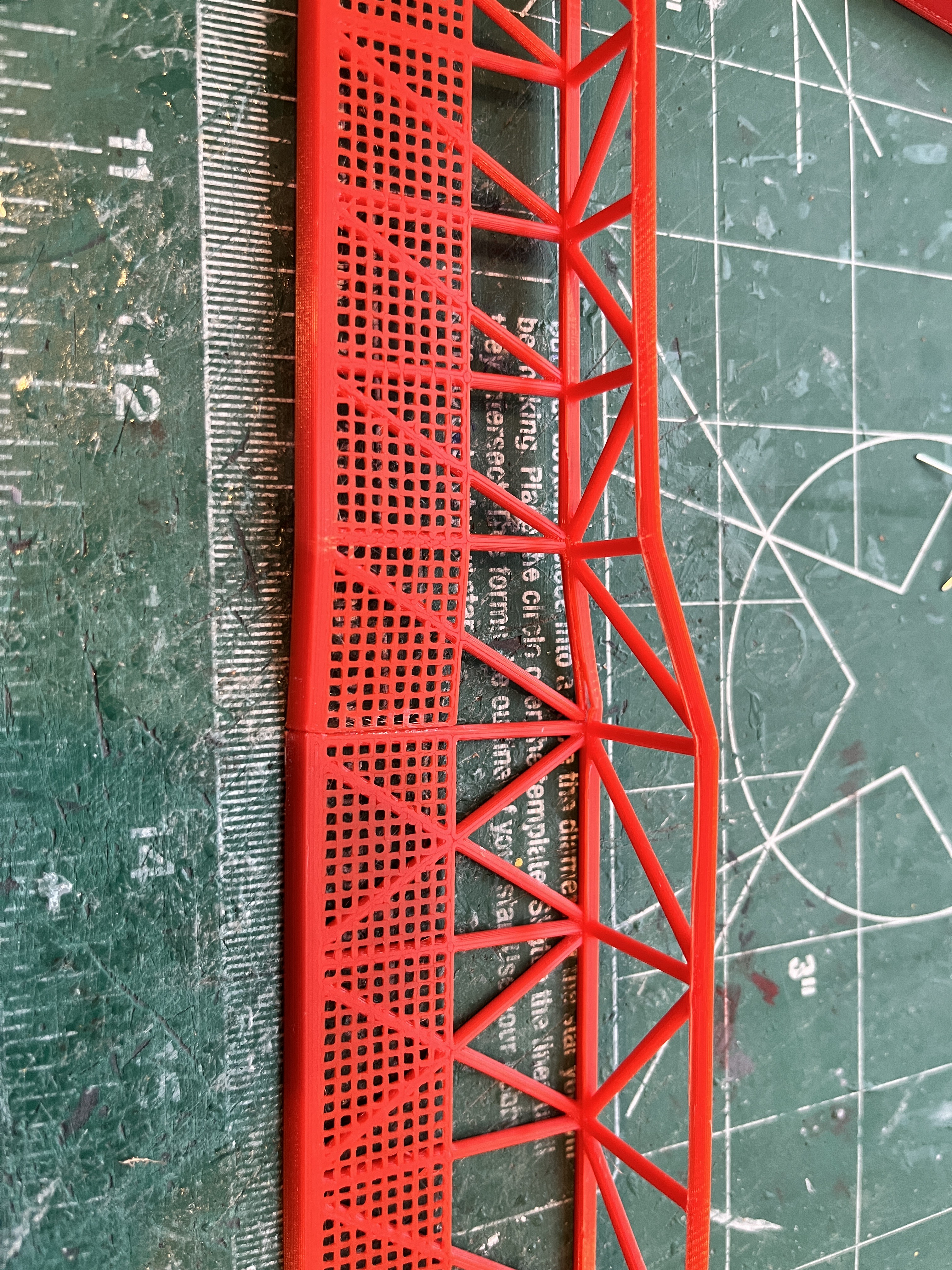
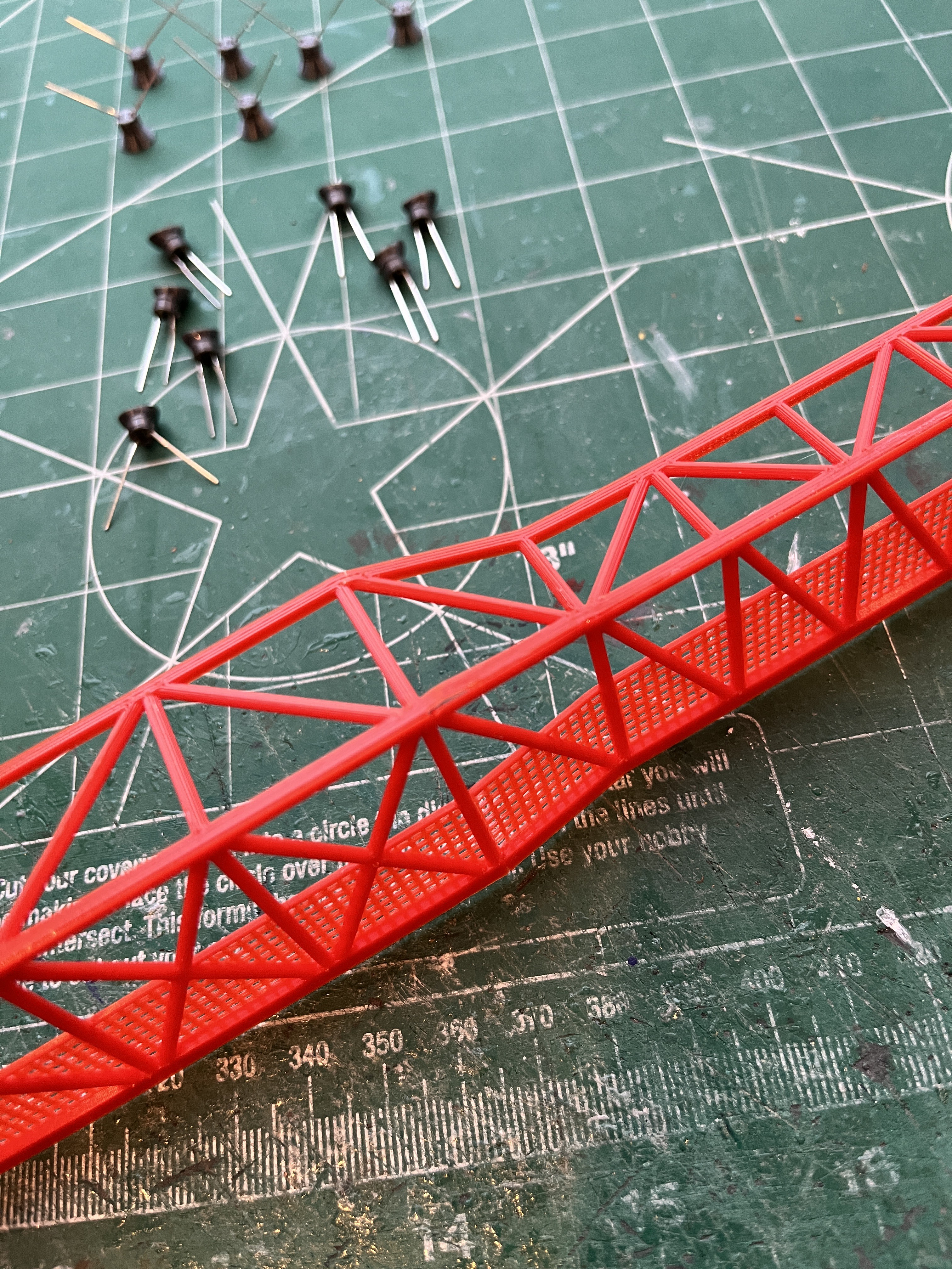
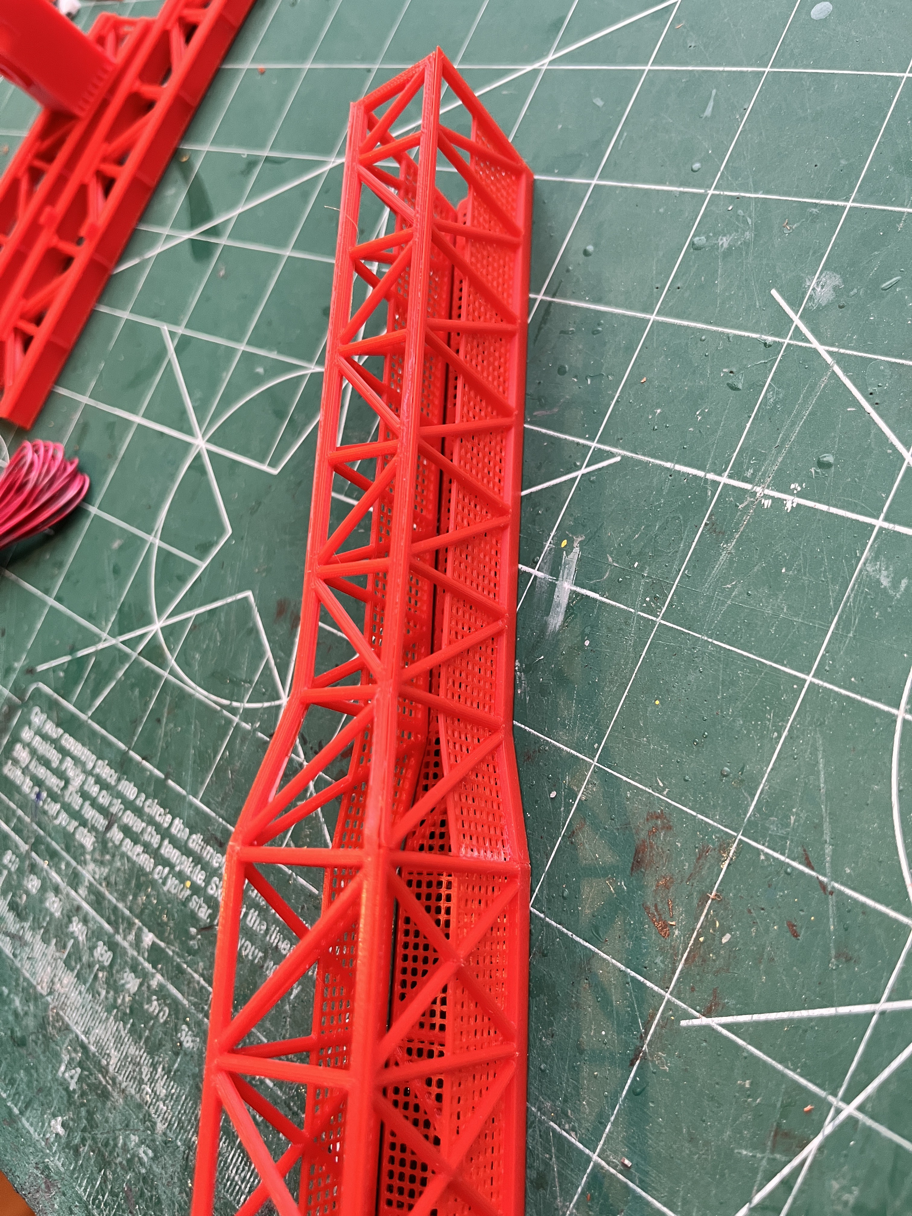
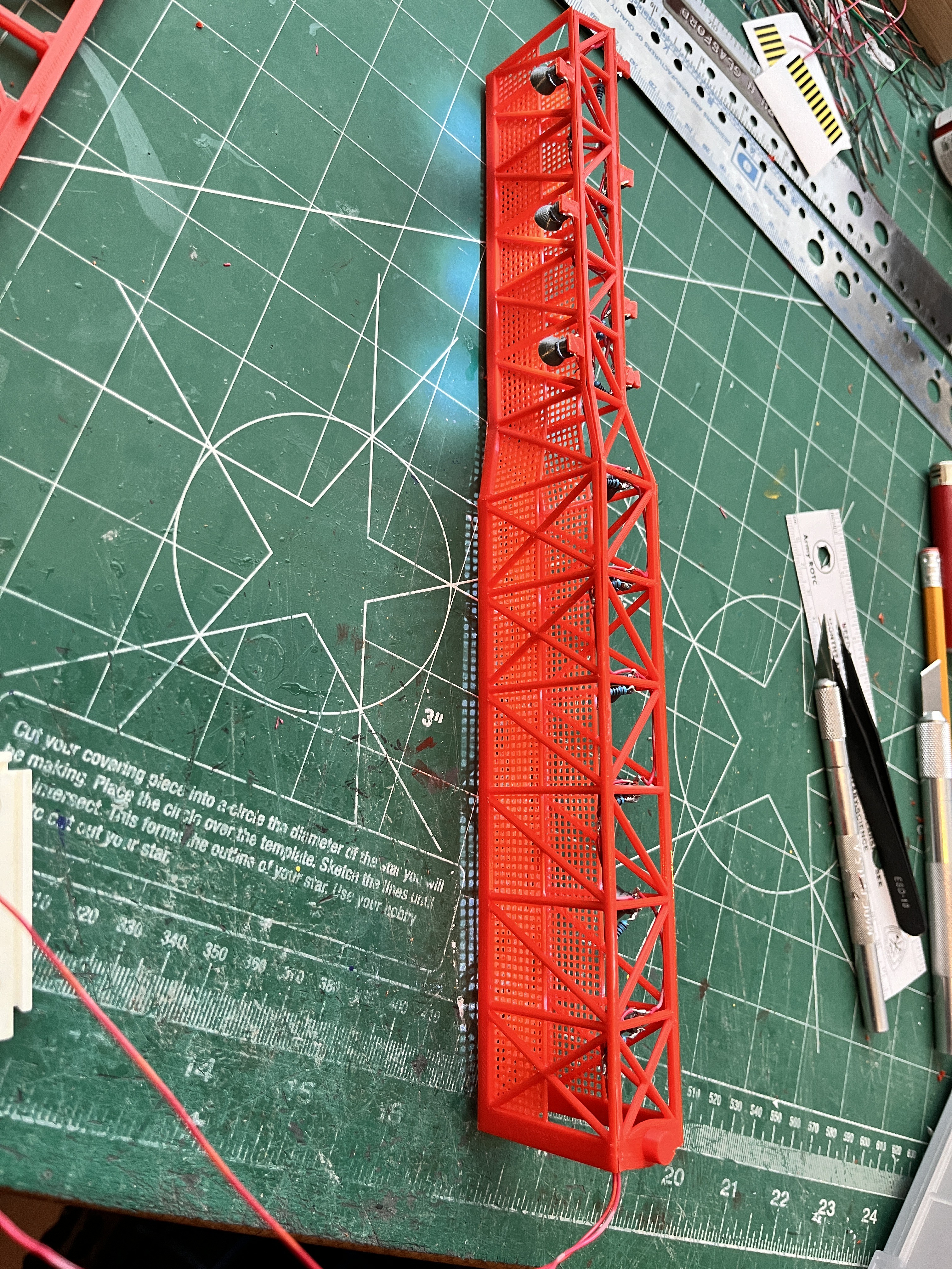
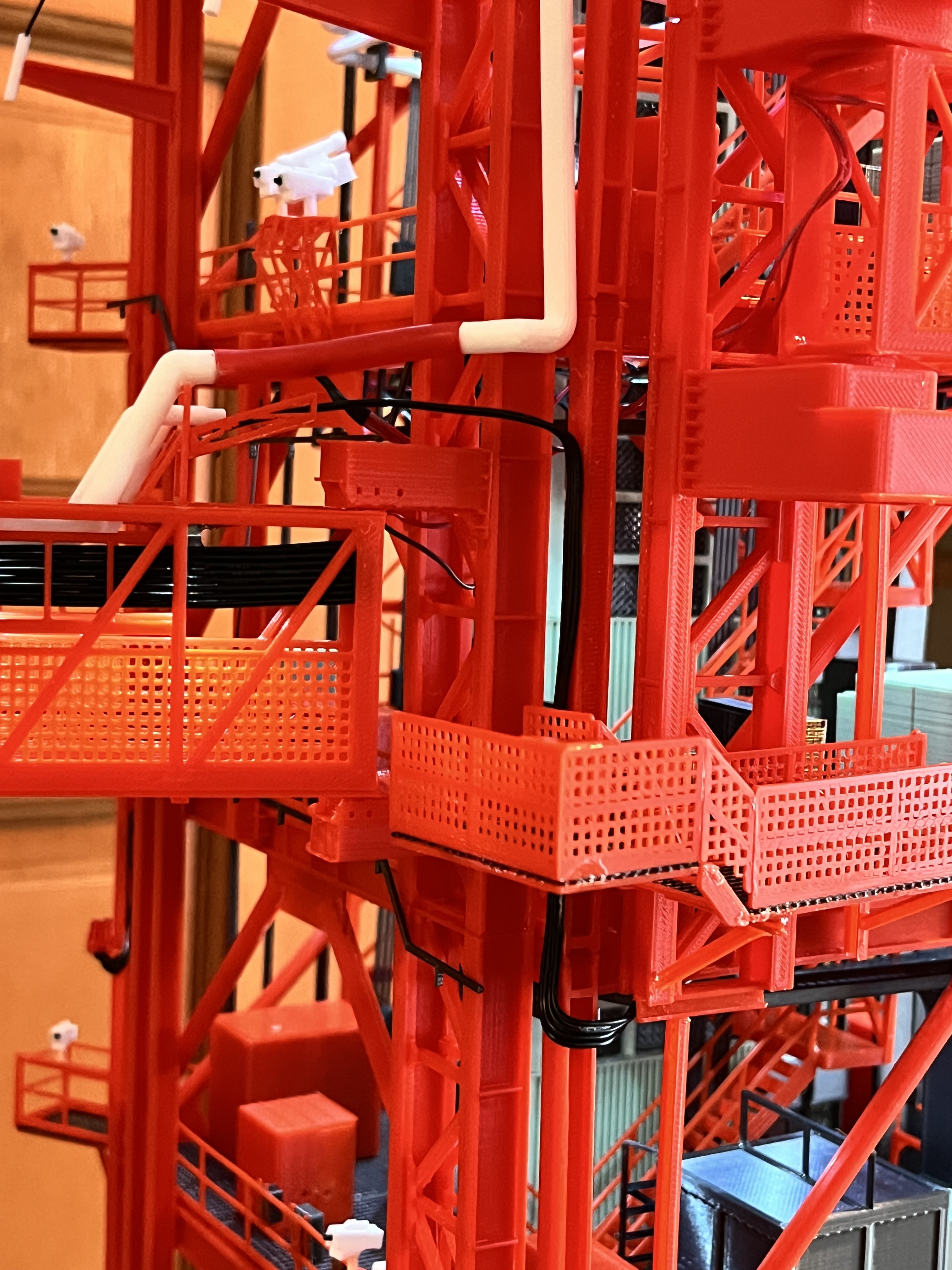
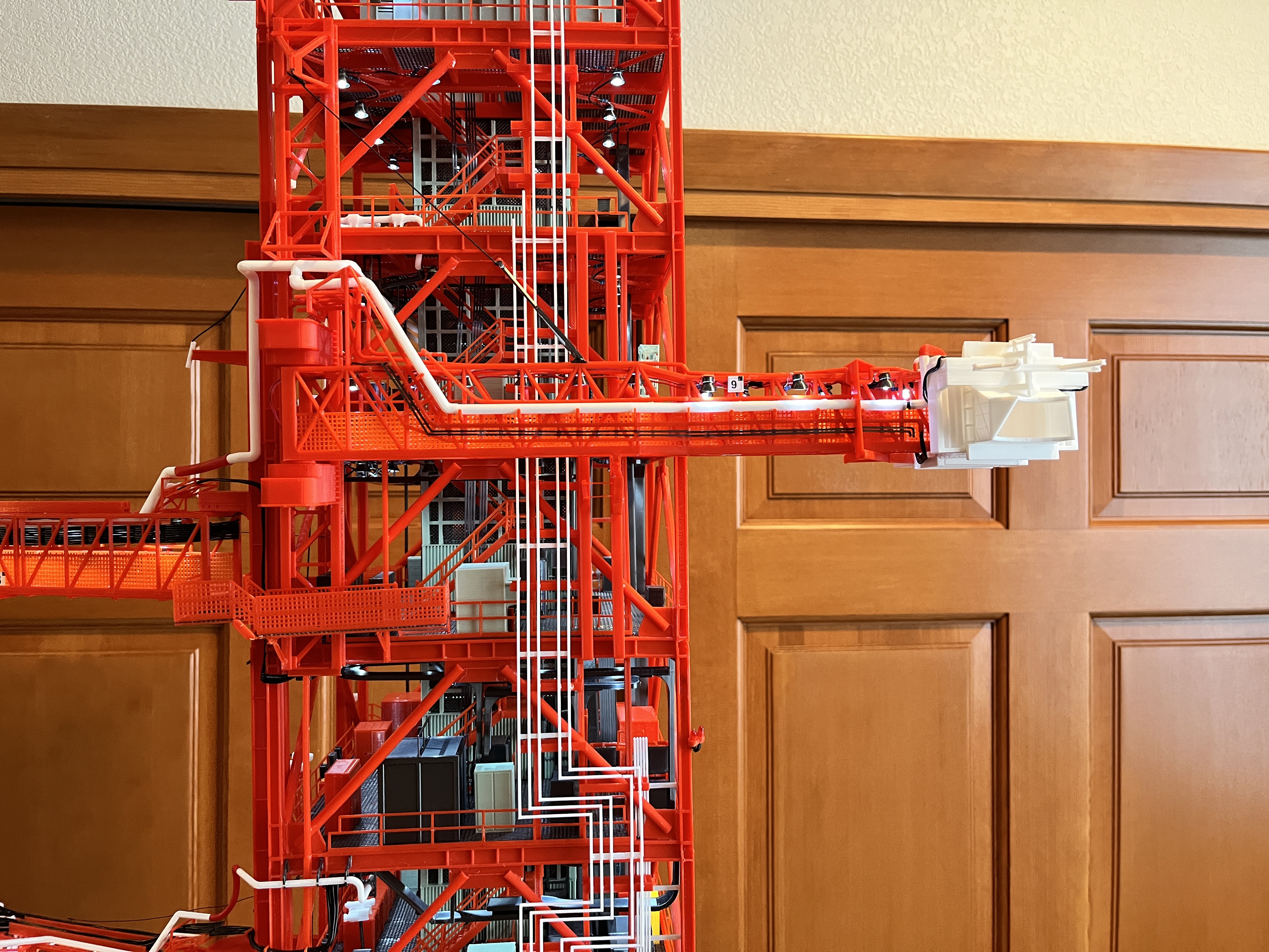
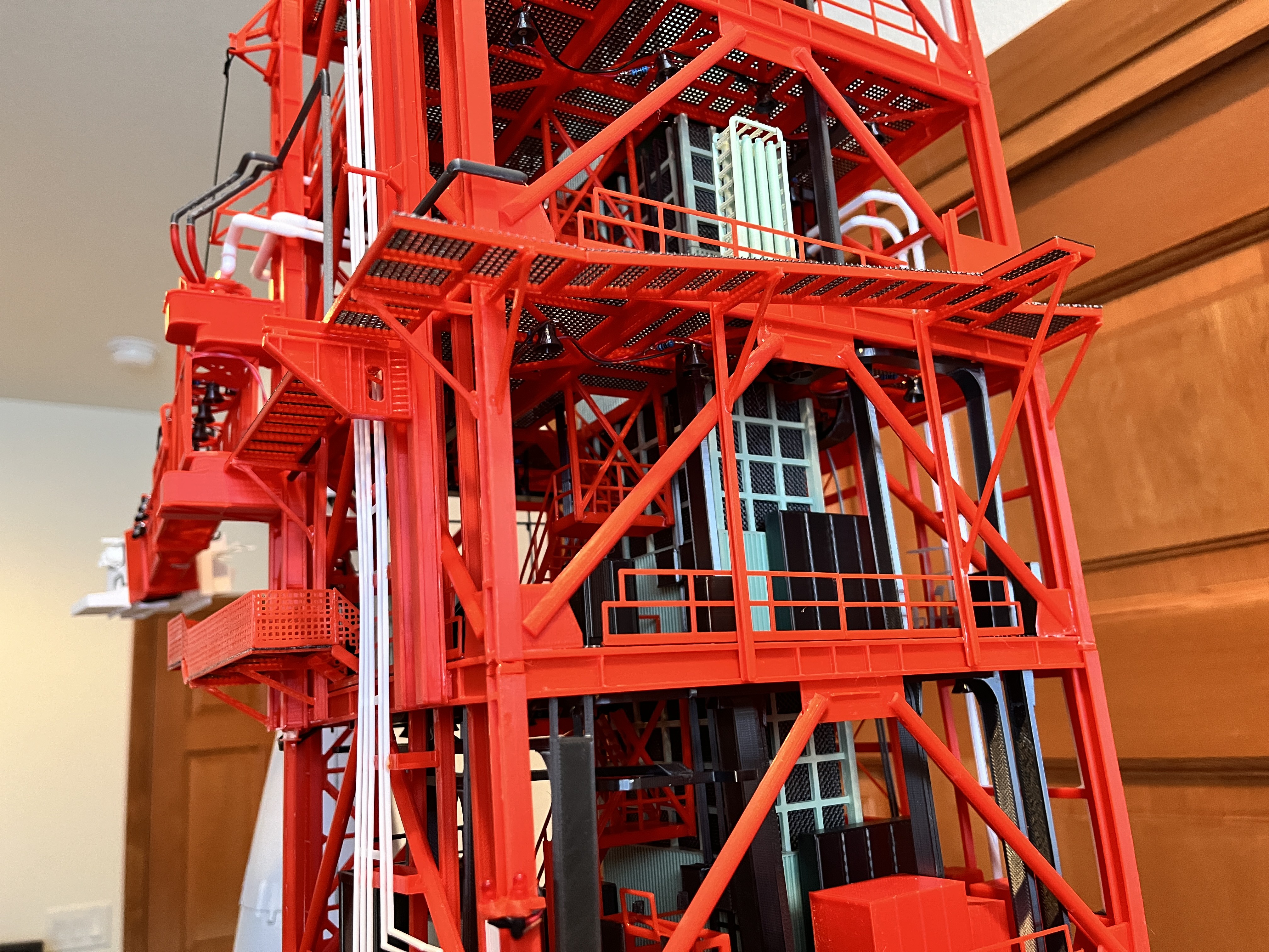
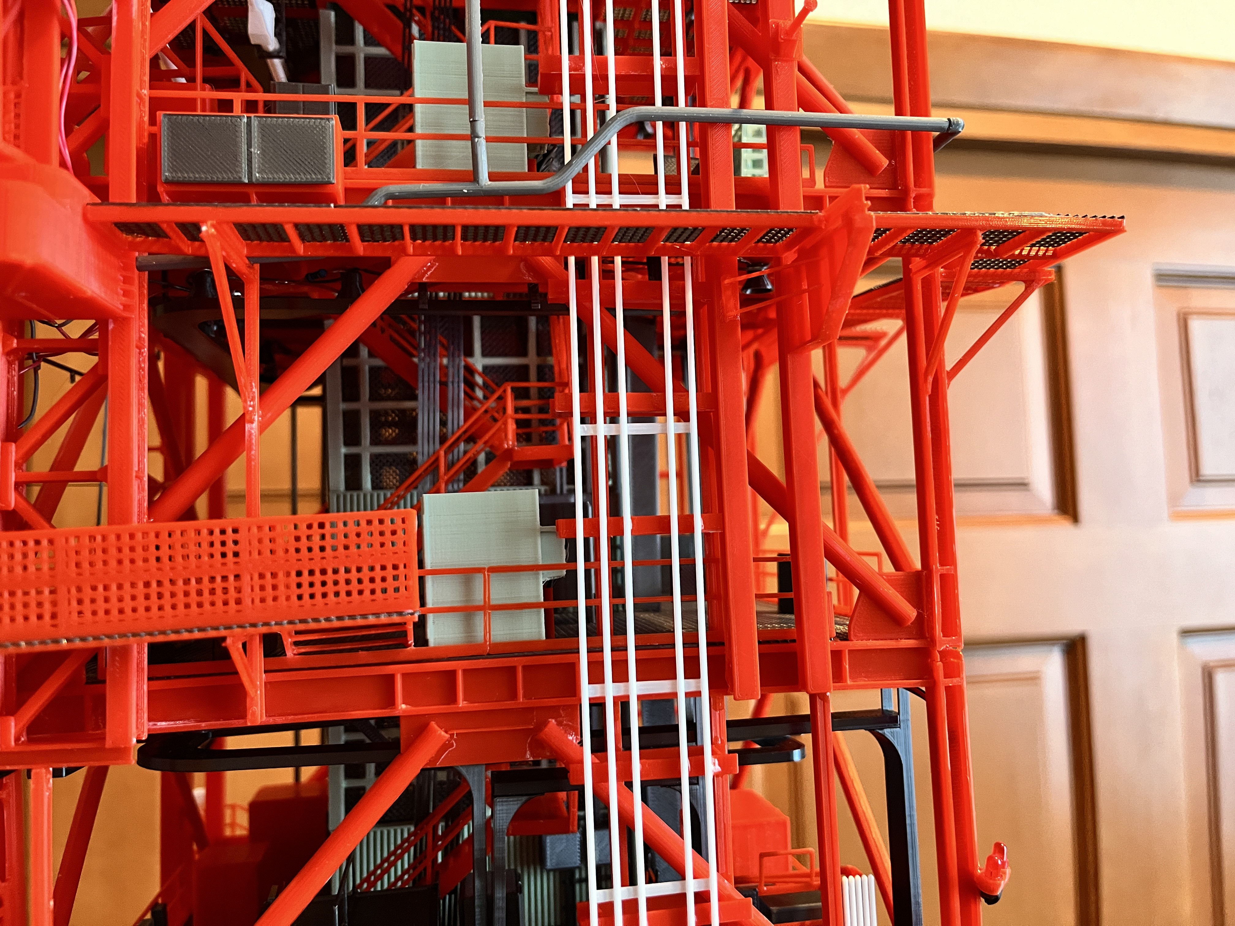
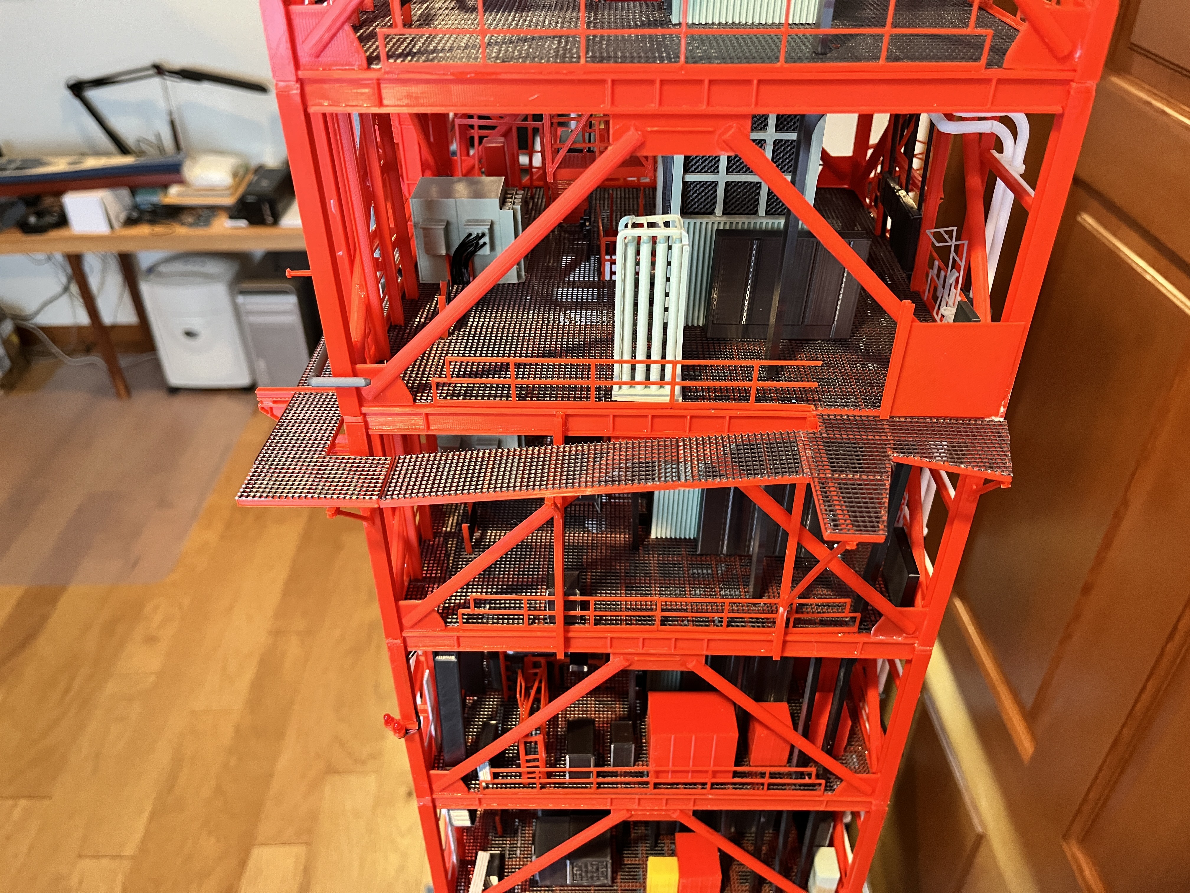
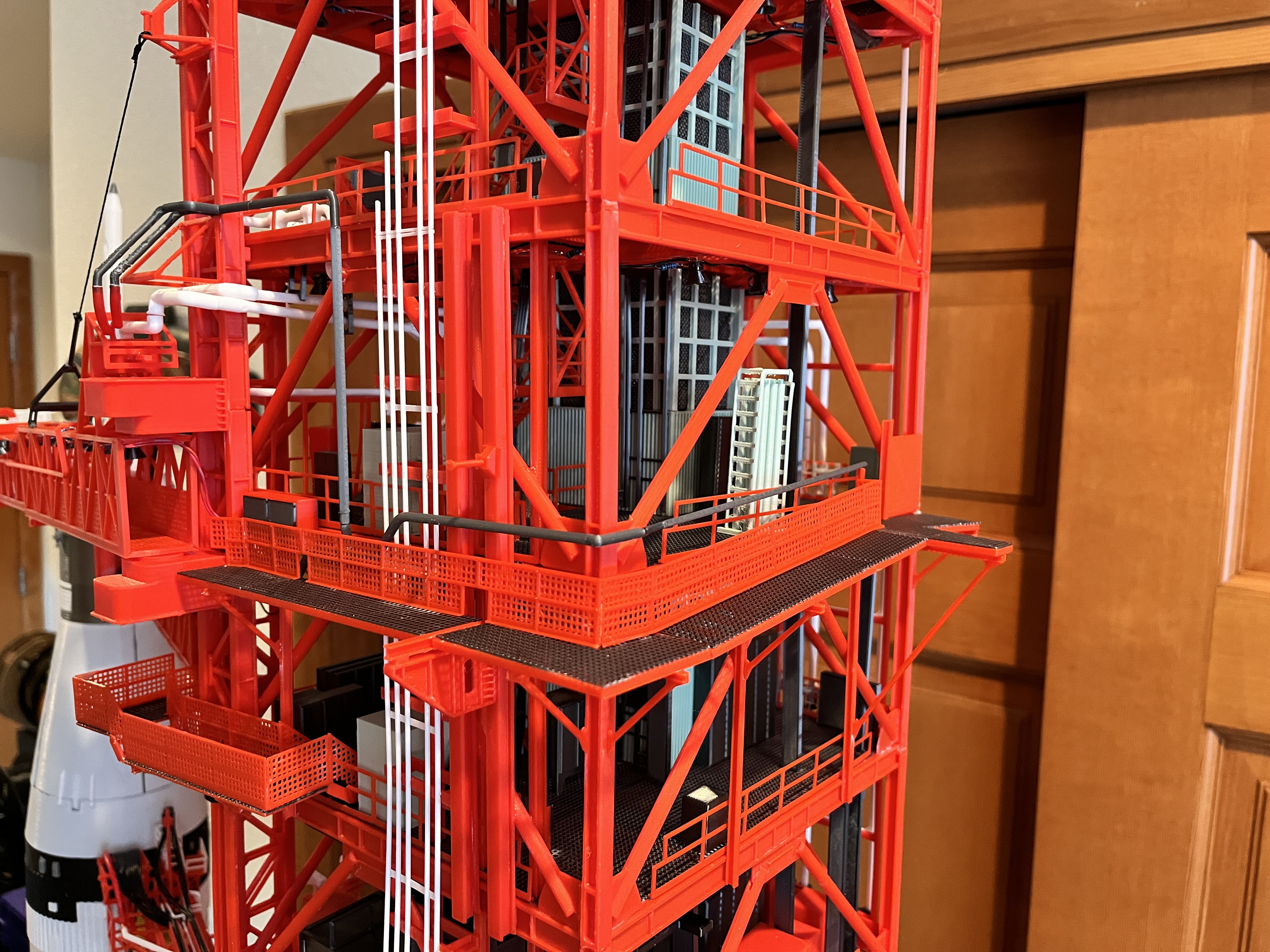
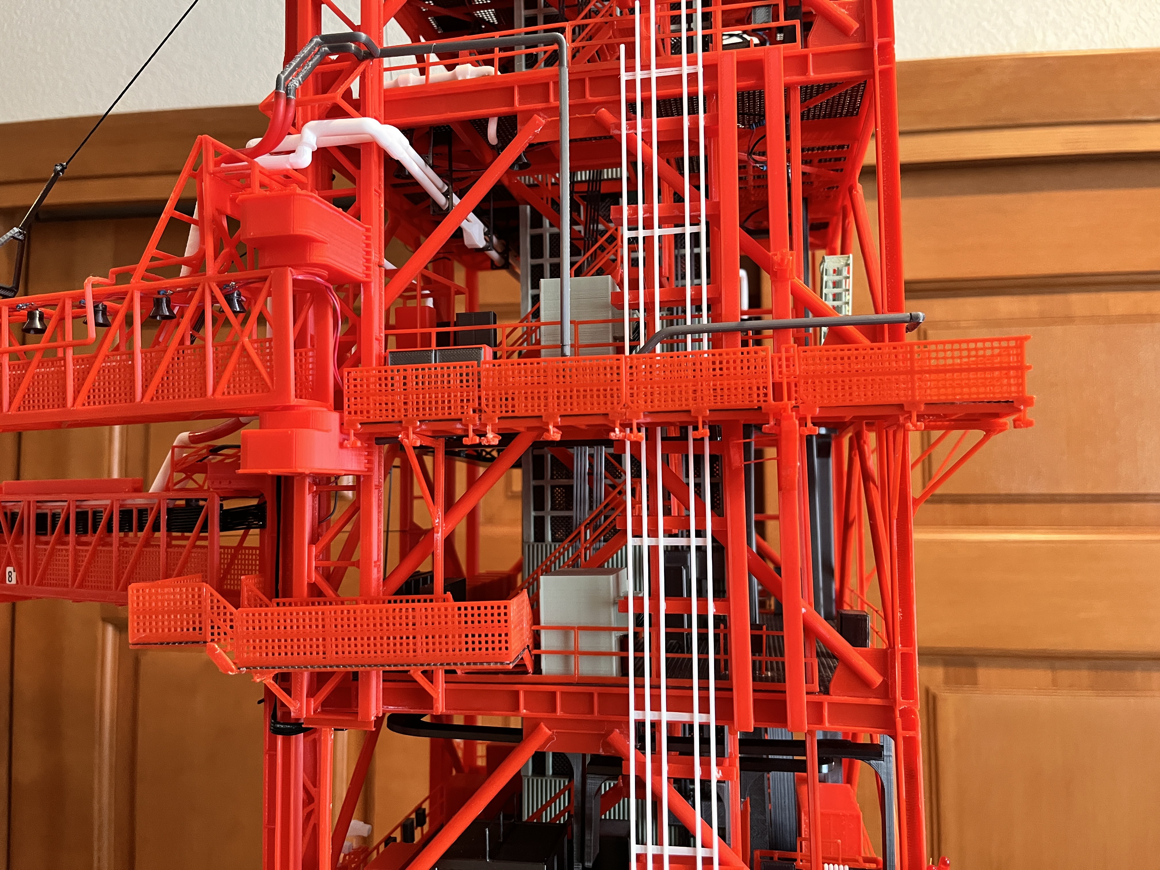
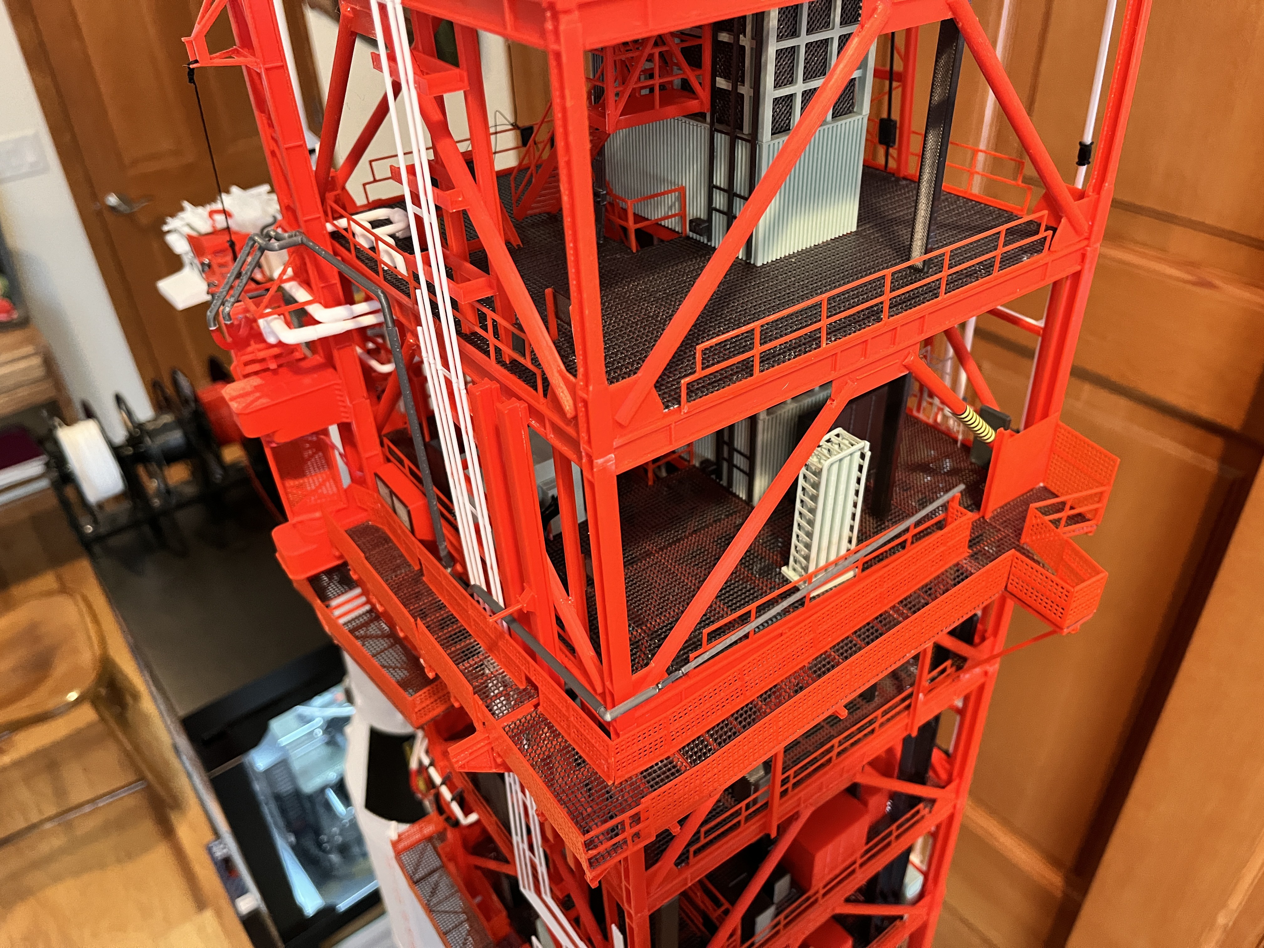
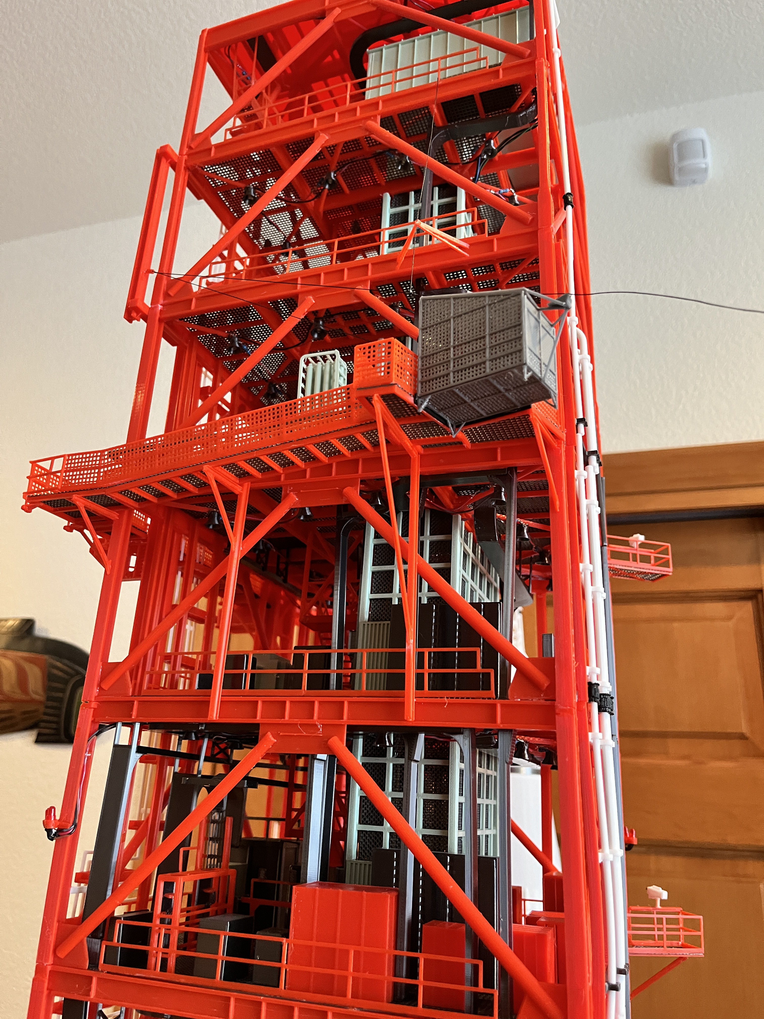
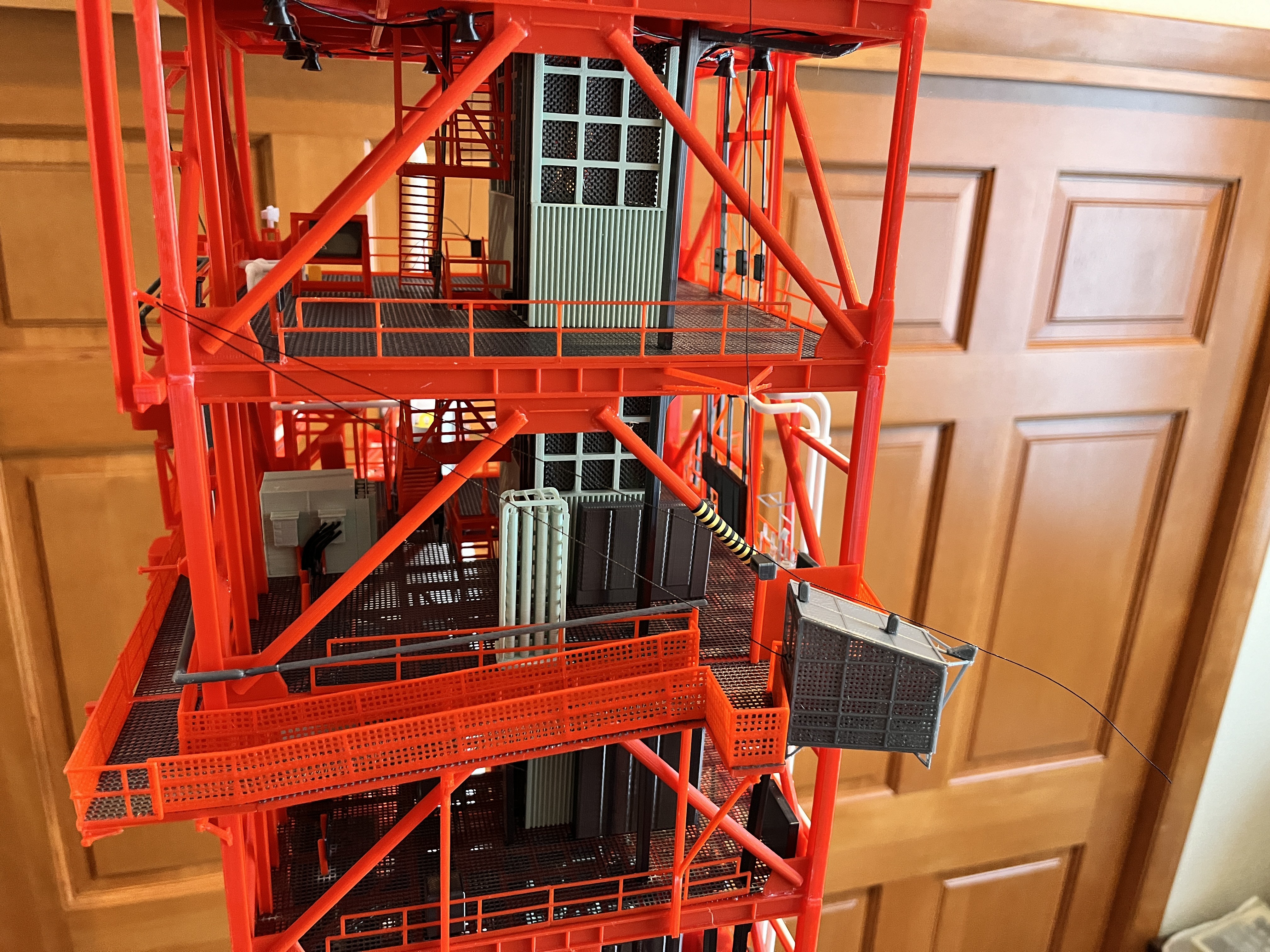
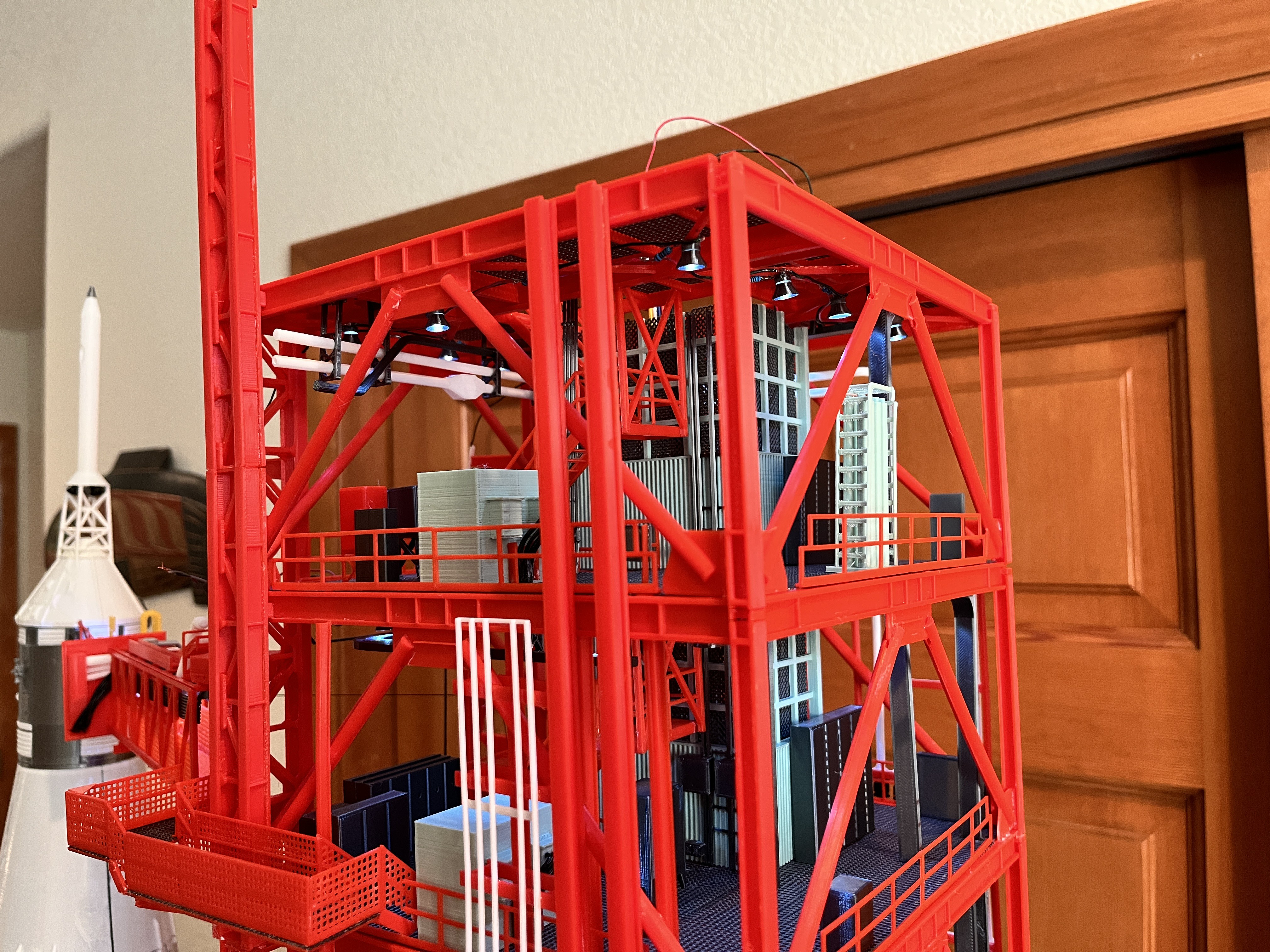
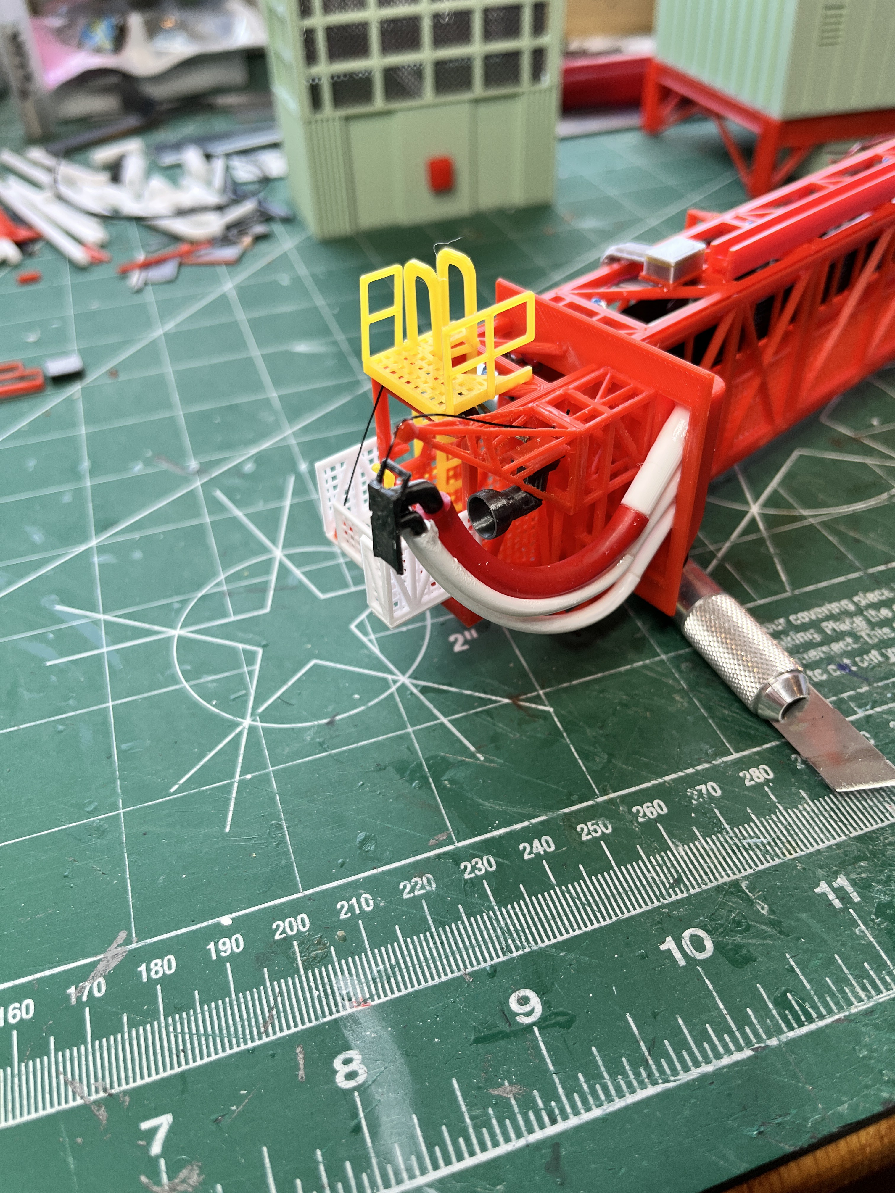
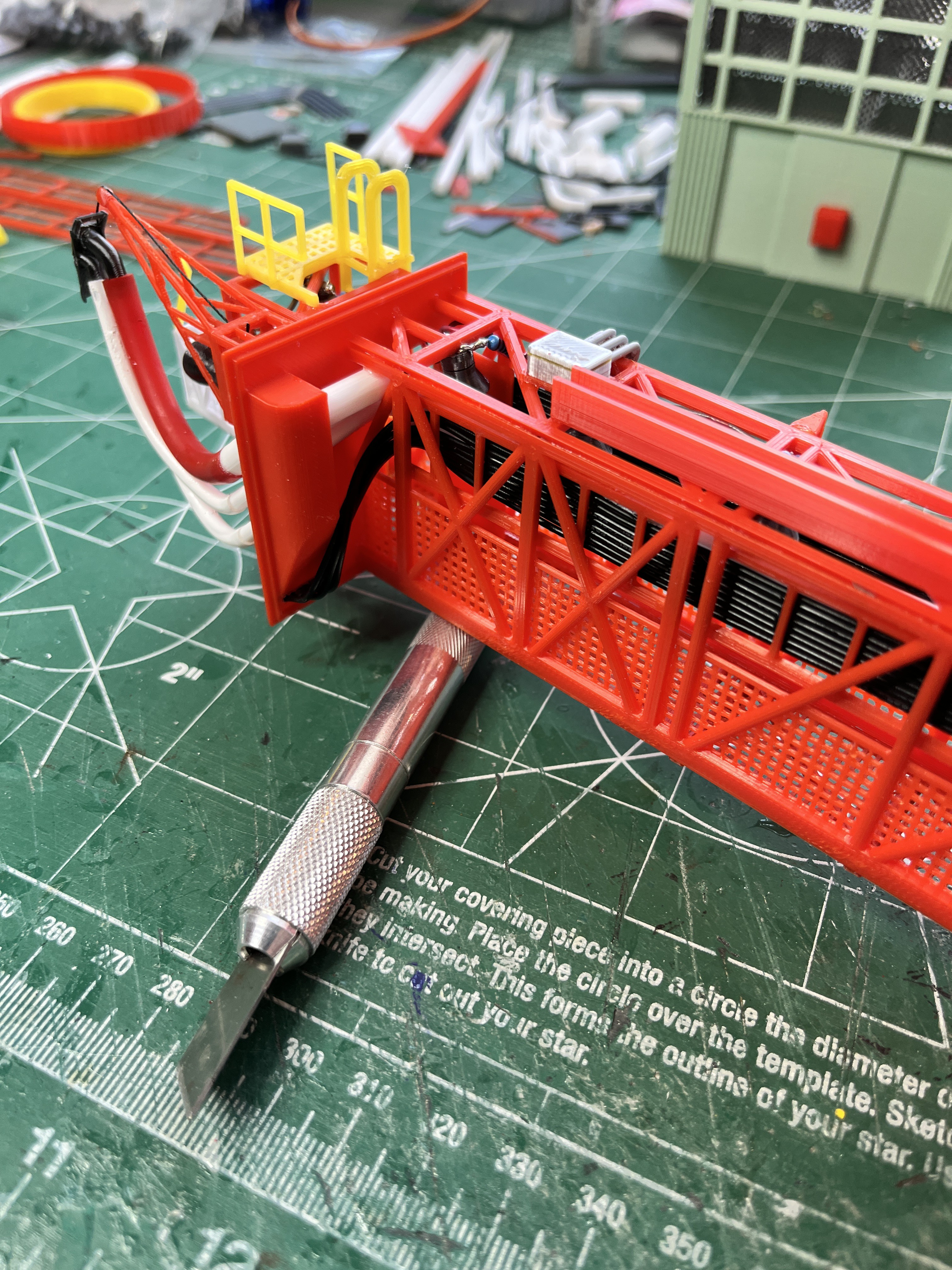
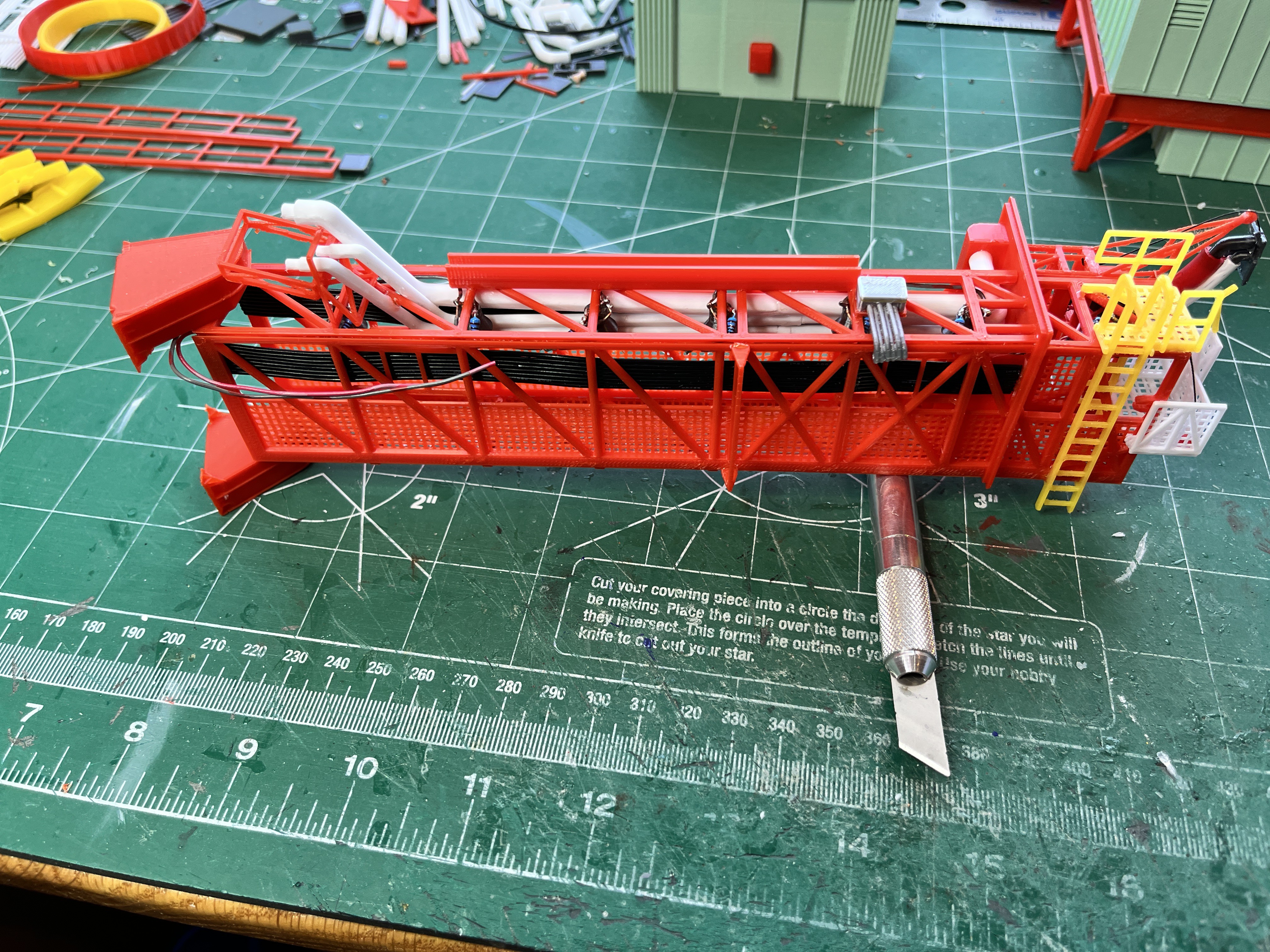
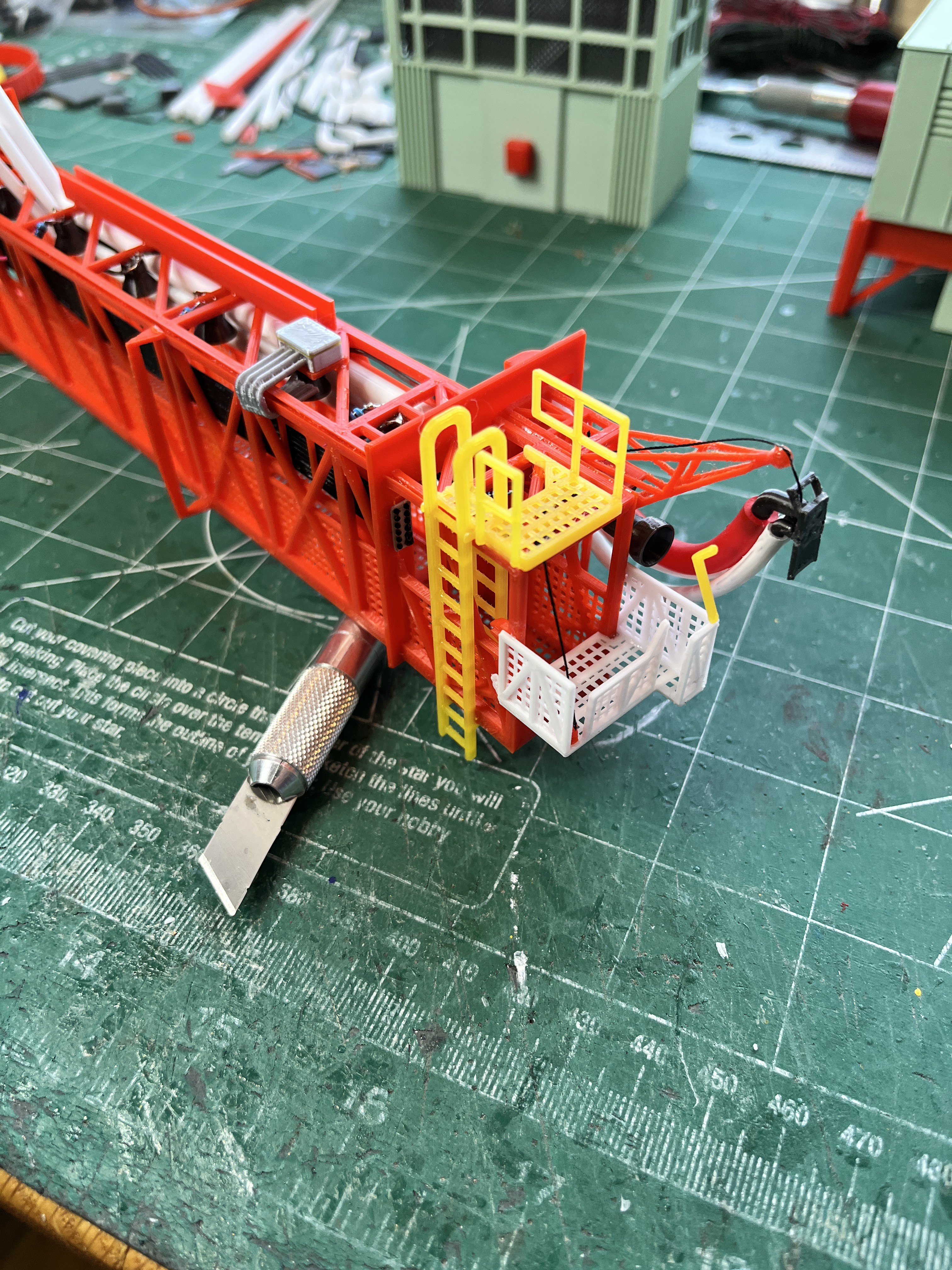
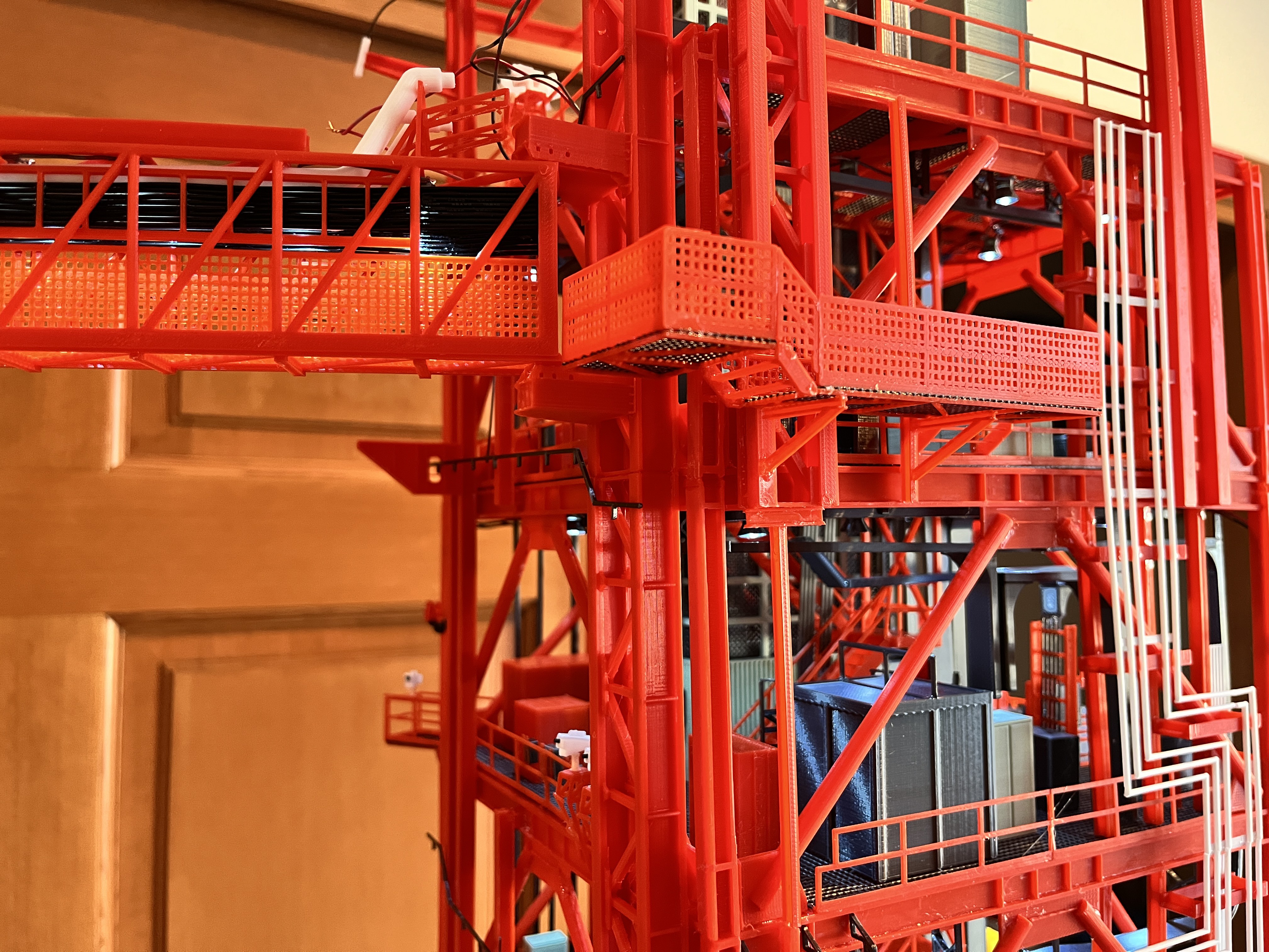
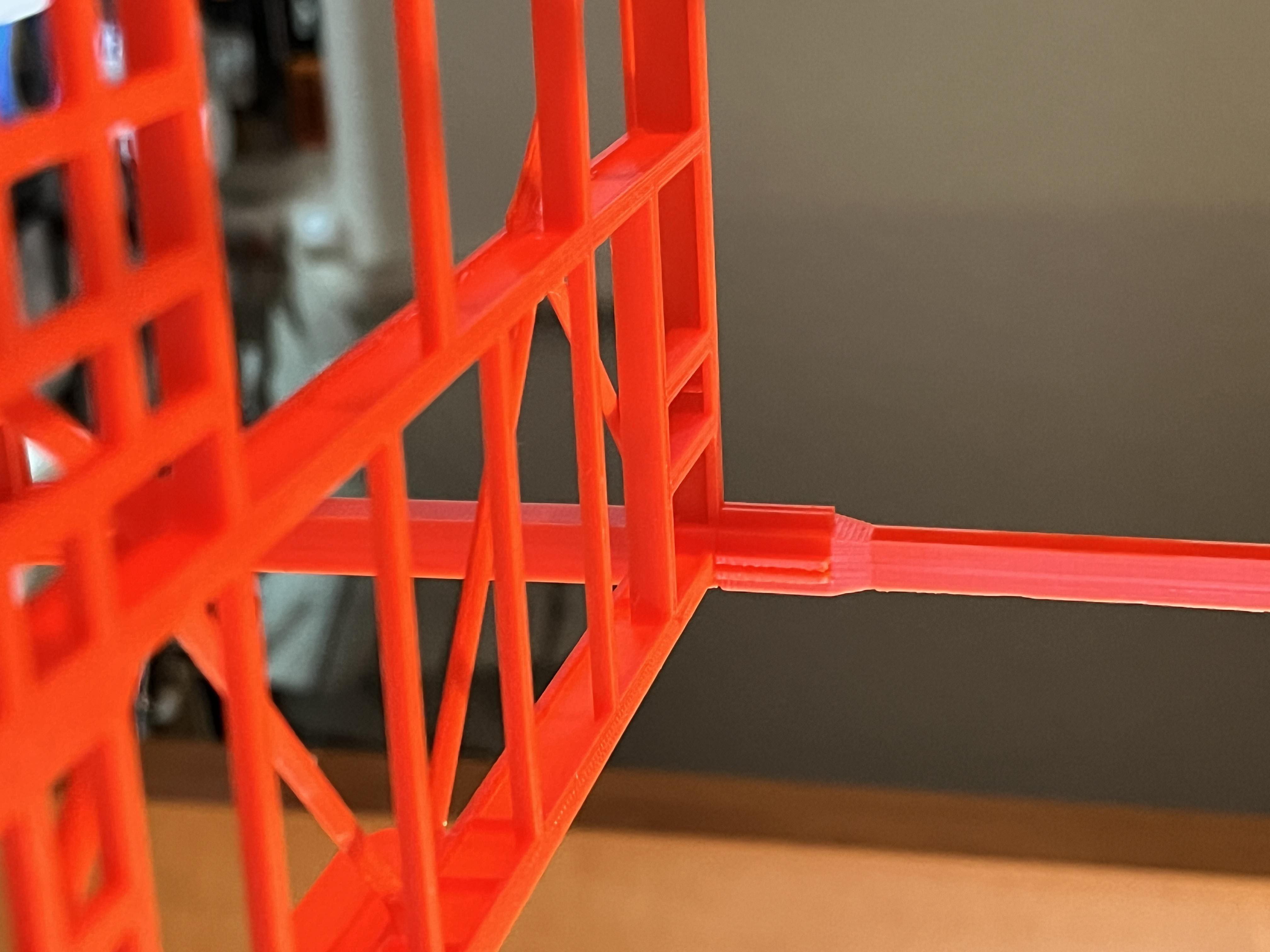
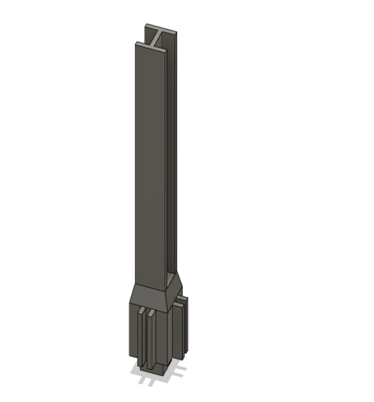
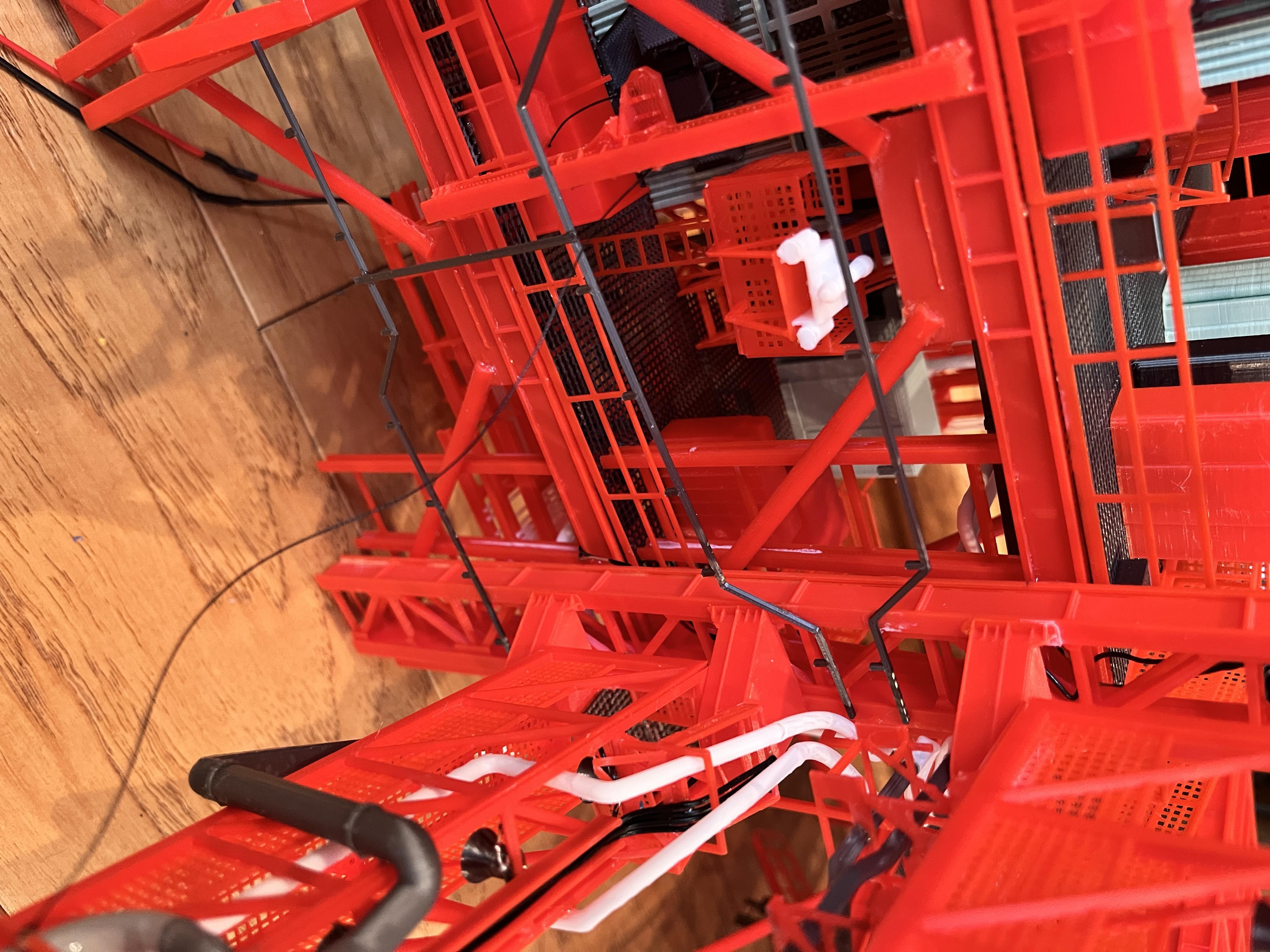
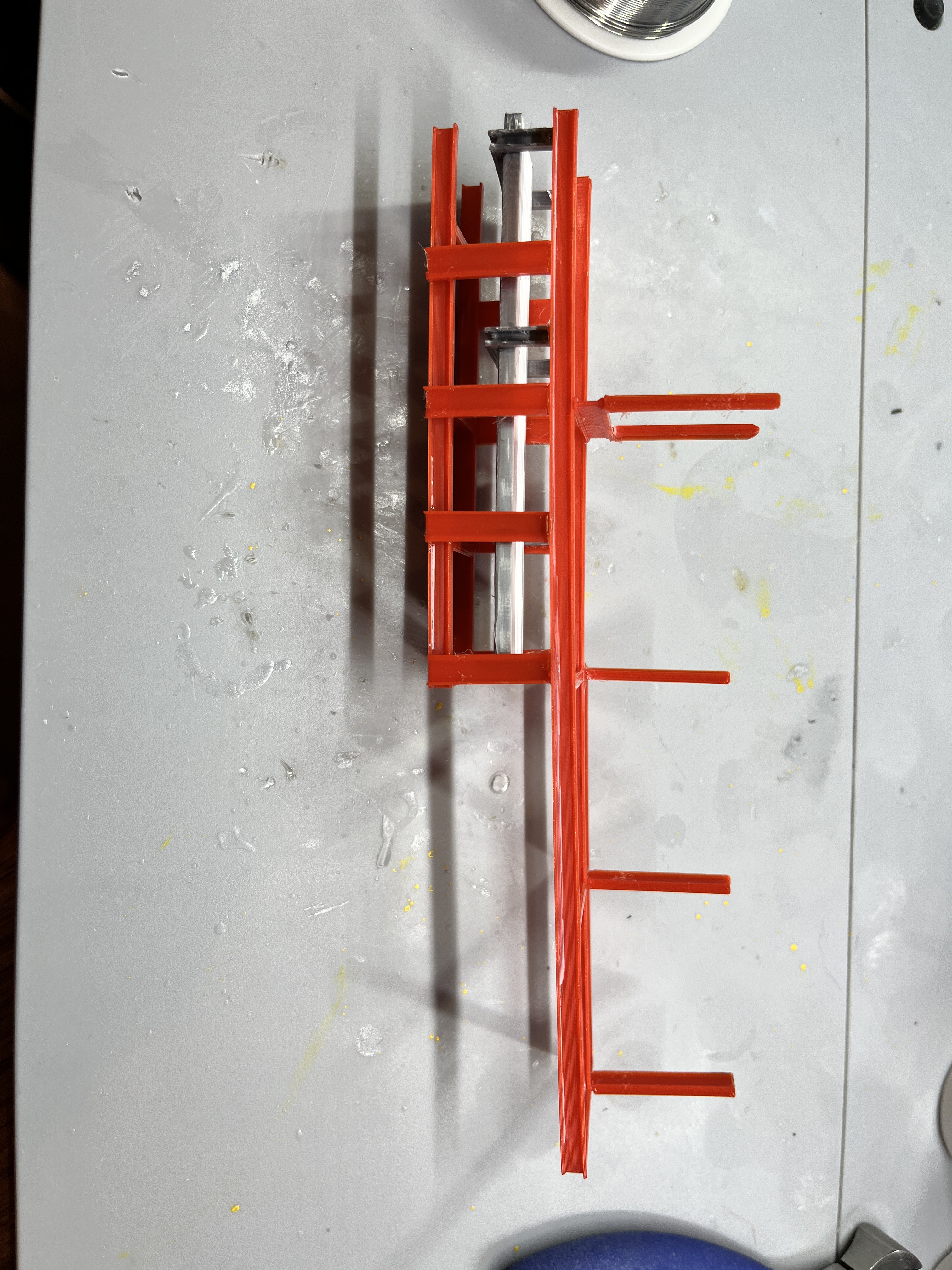
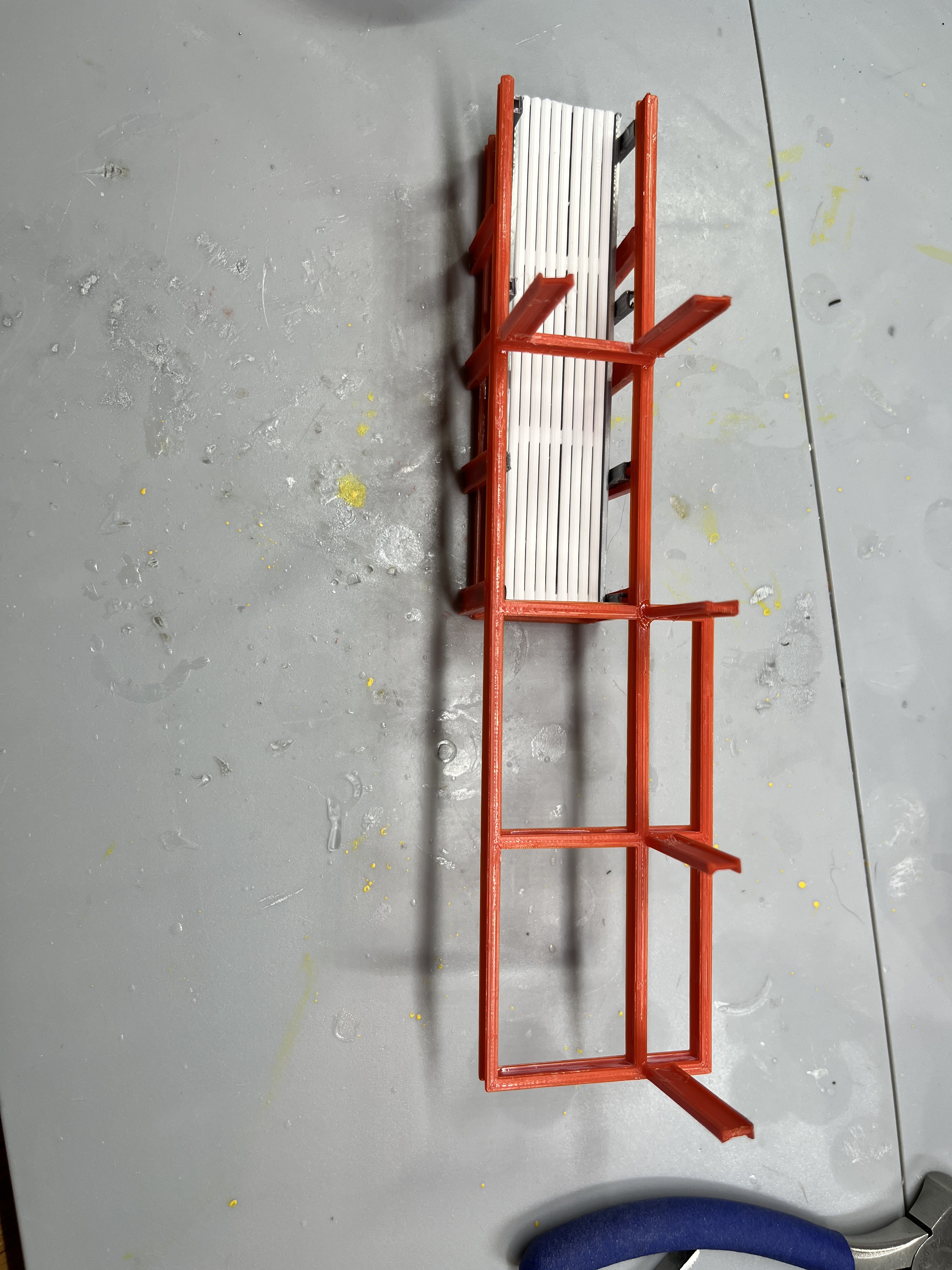
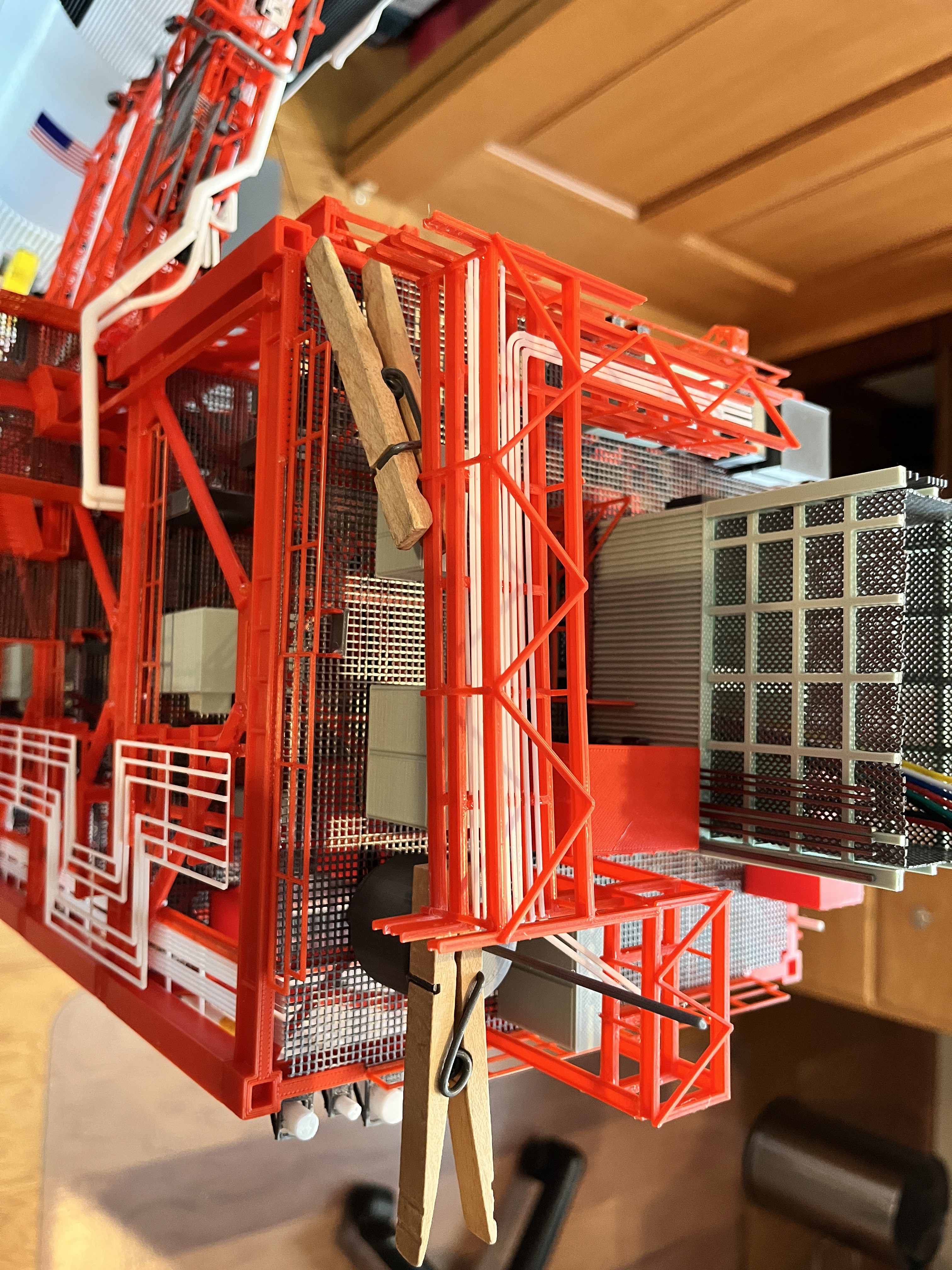
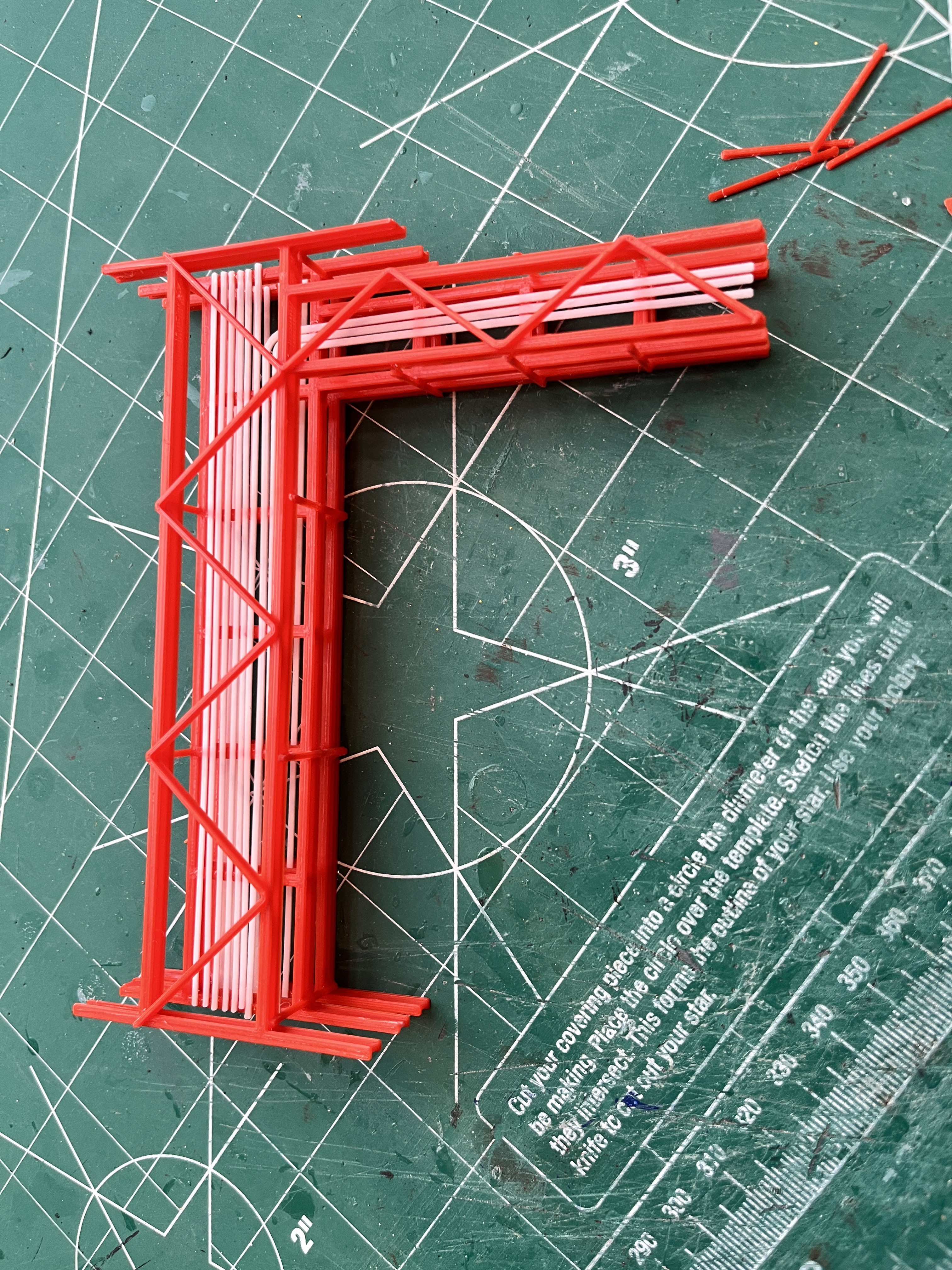
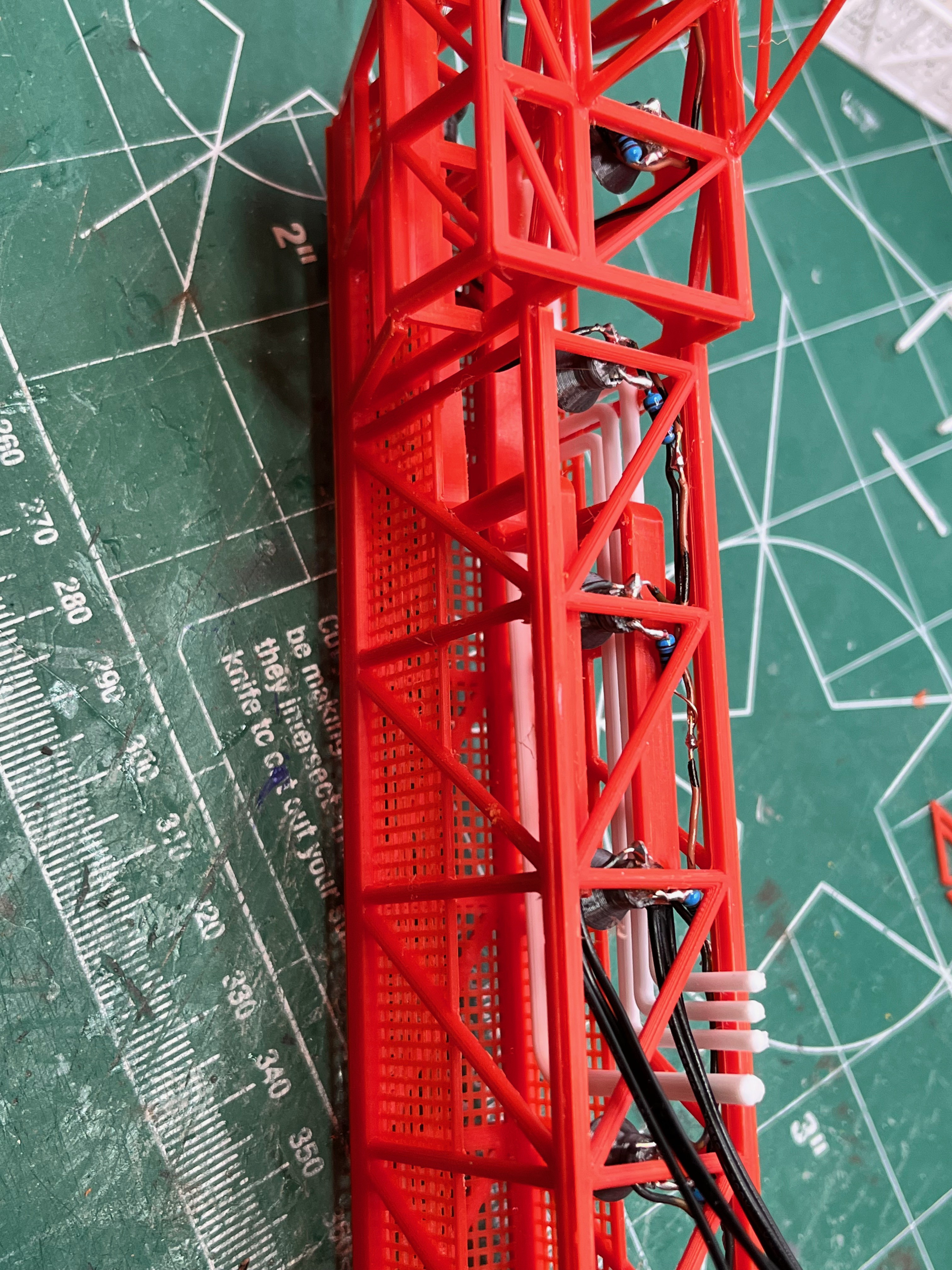
The umbilical tower is the hardest part by far. This consists of the following models.
- Structure Level 0-30 - Complete
- Structure Level 30-60 - Complete
- Structure Levels 60-380 - Complete
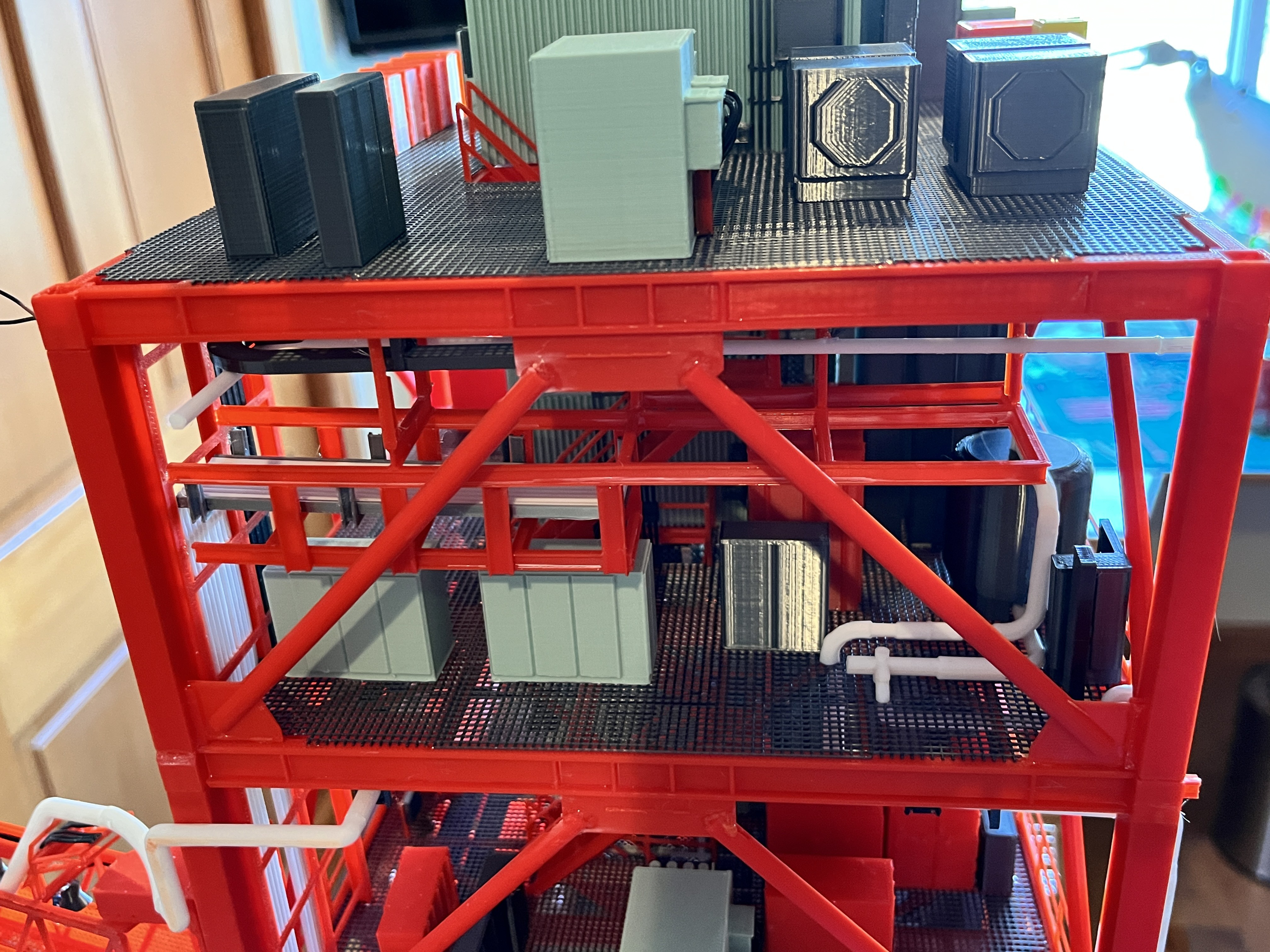
- Mid-Floor Structures - Complete
- Elevator - Complete
- Stairs - Complete
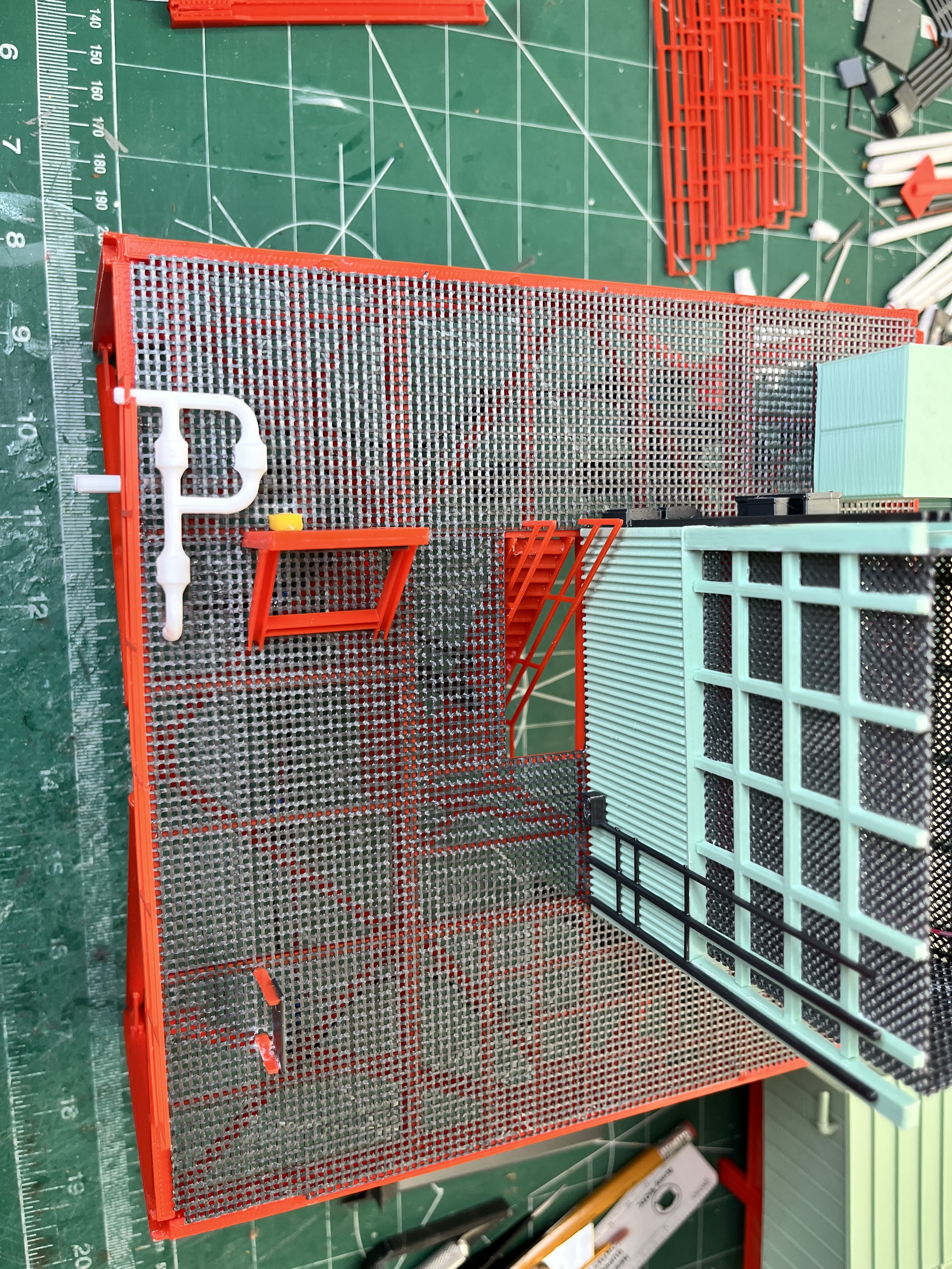
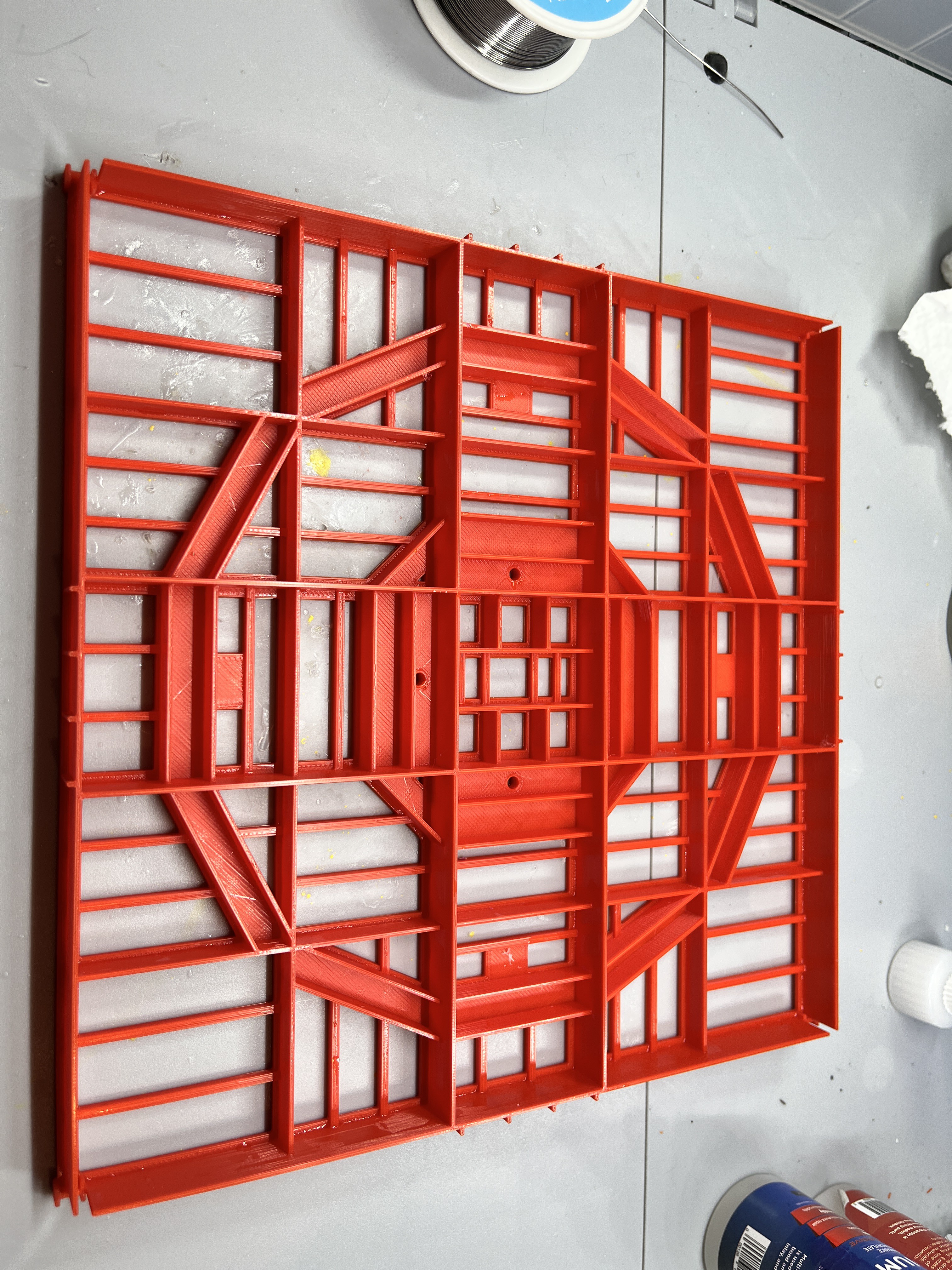
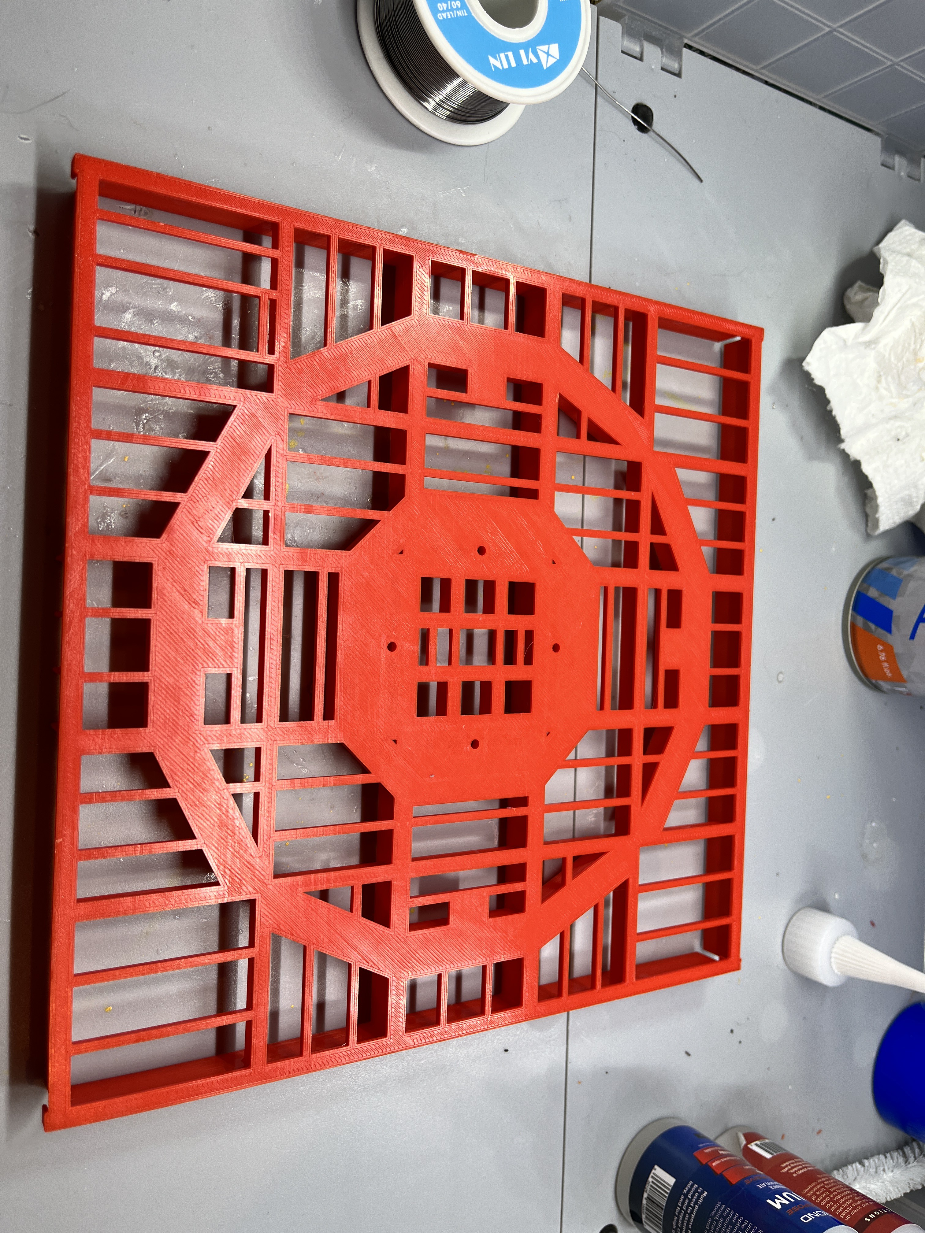
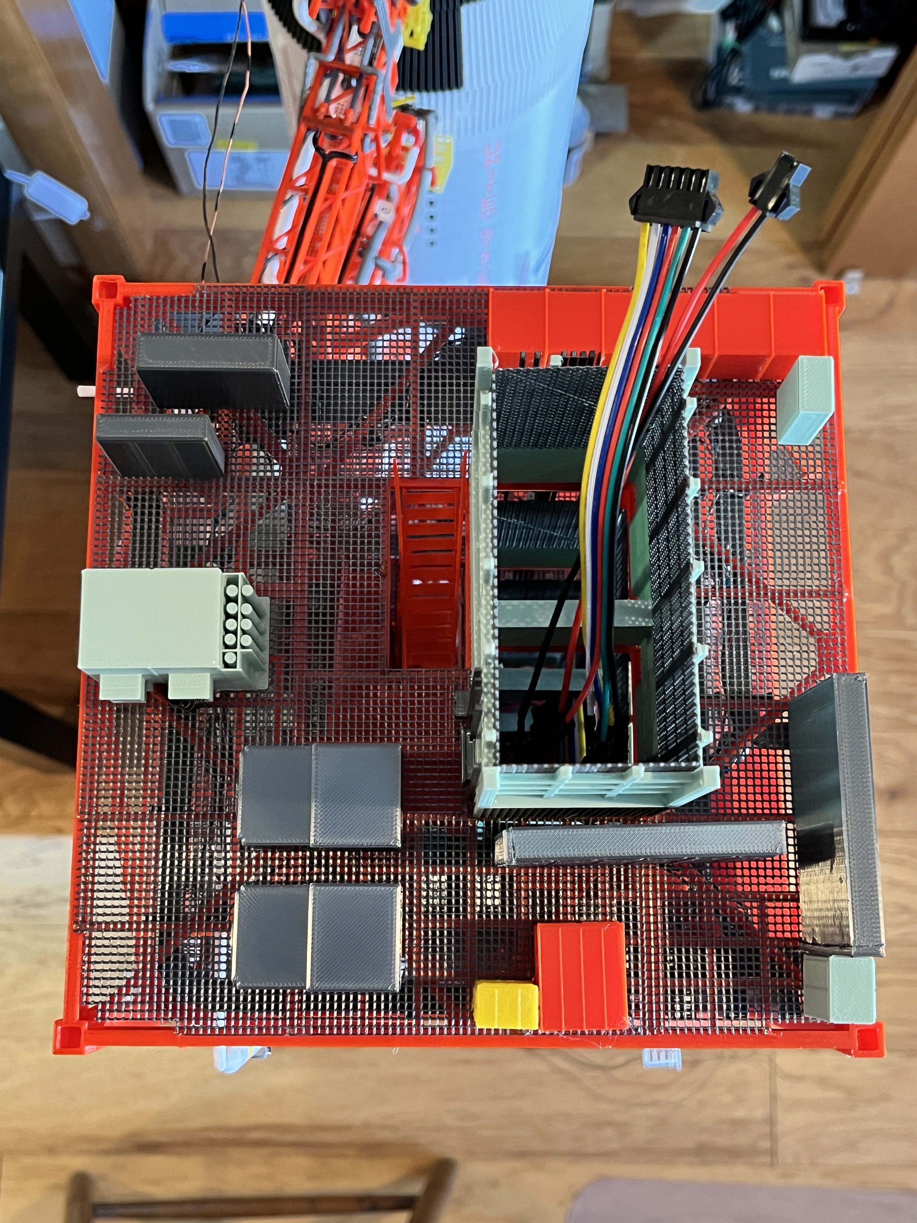
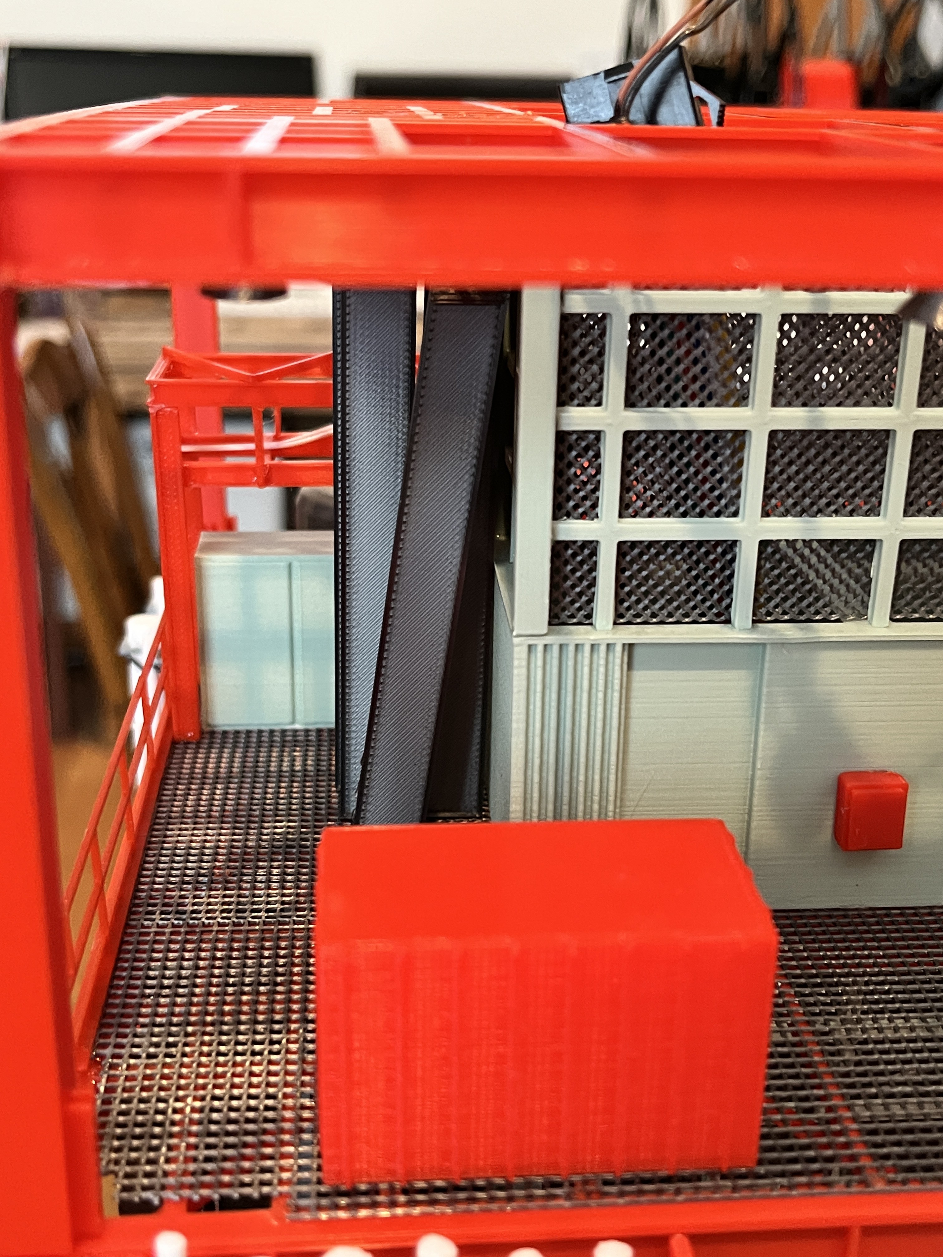
- Flooring - Complete
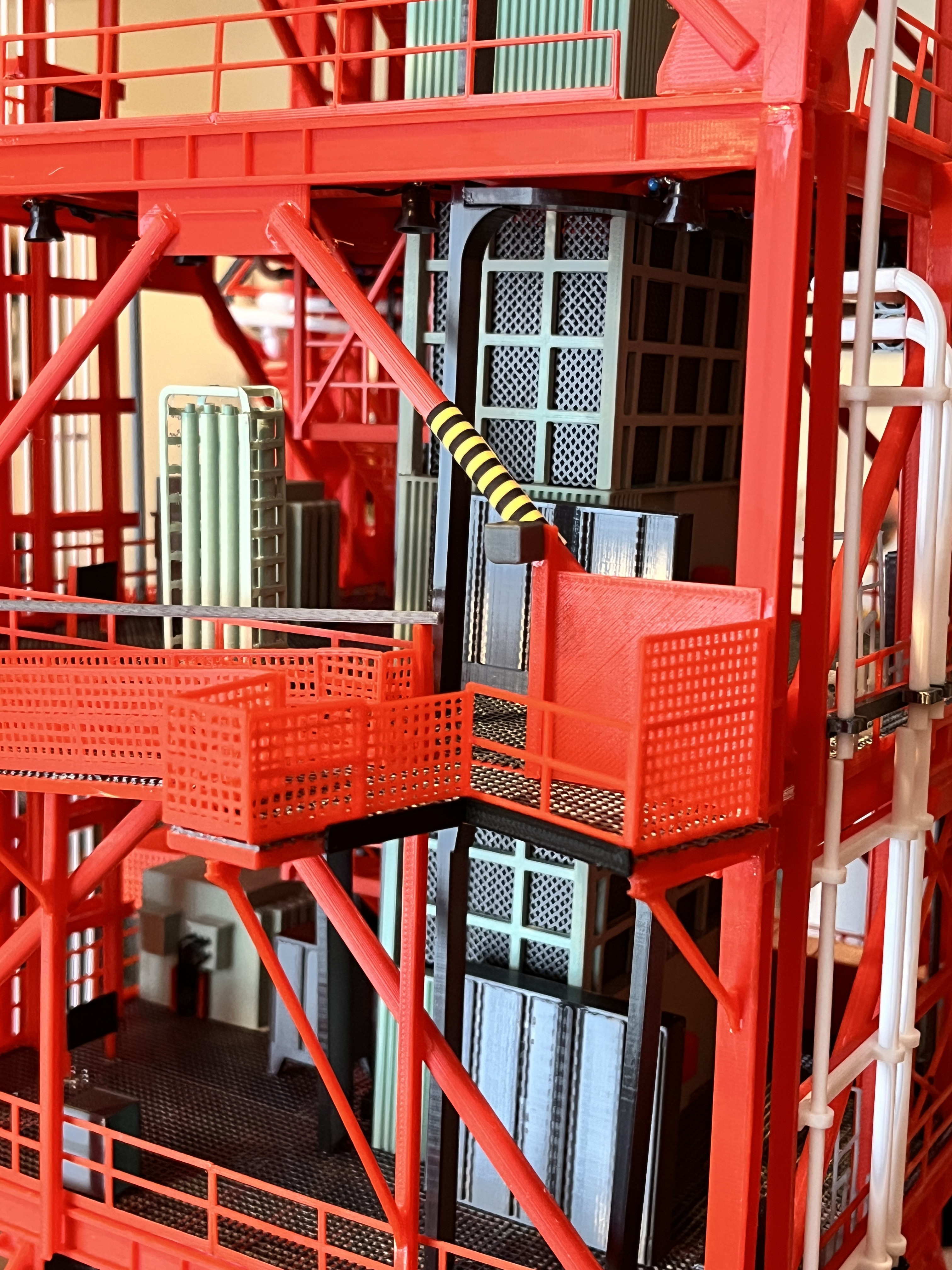
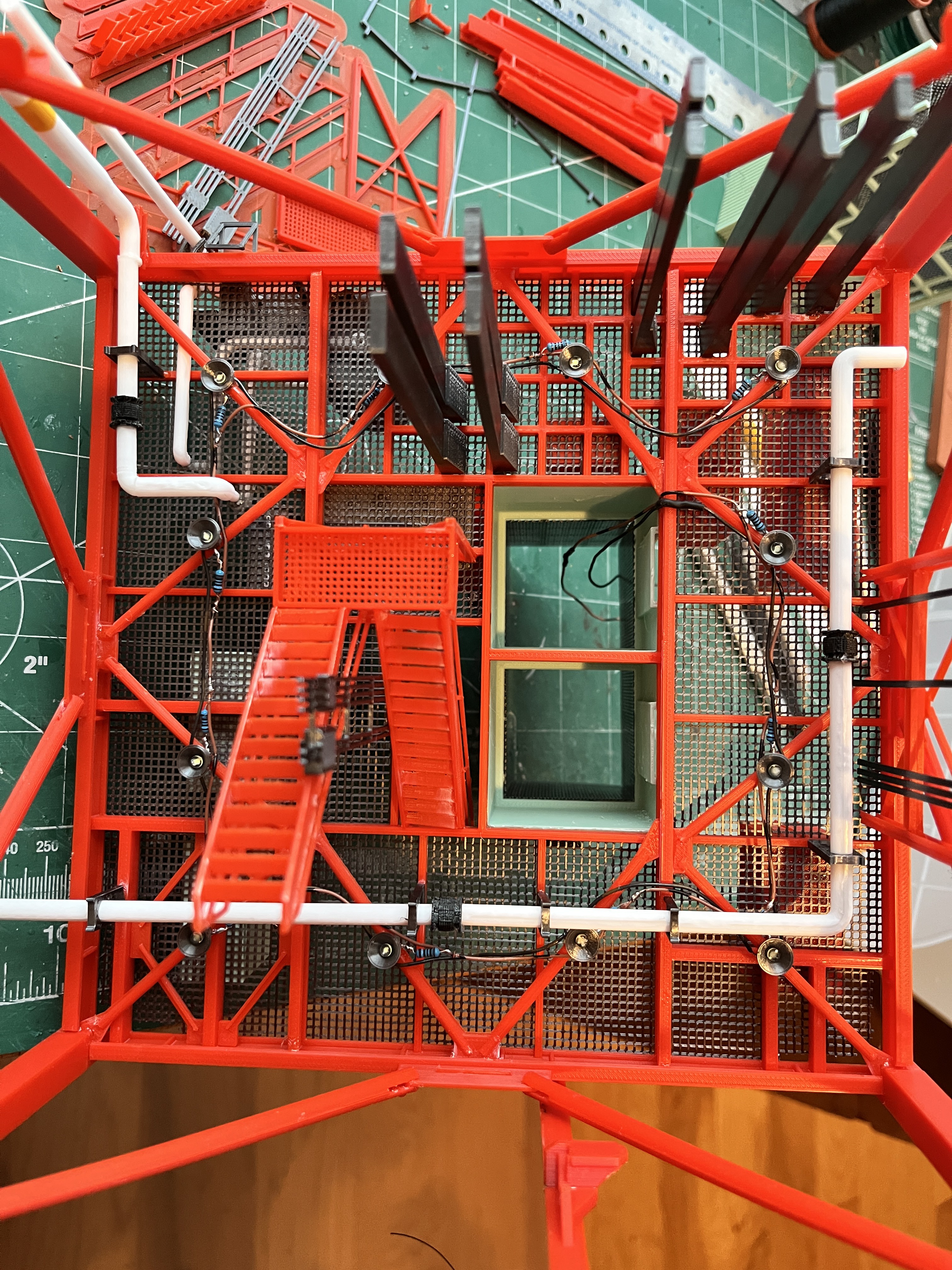
- Railing - Complete
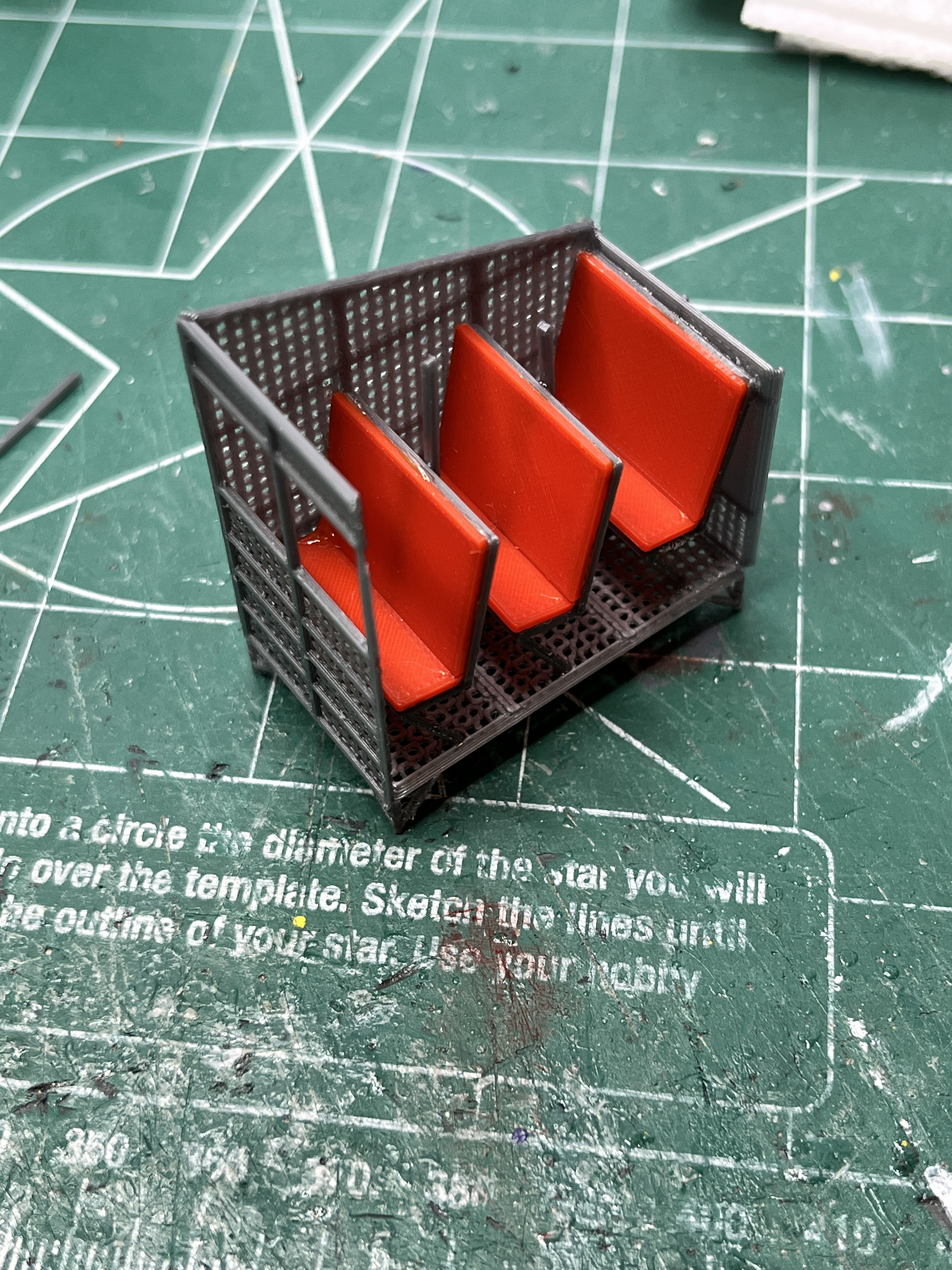
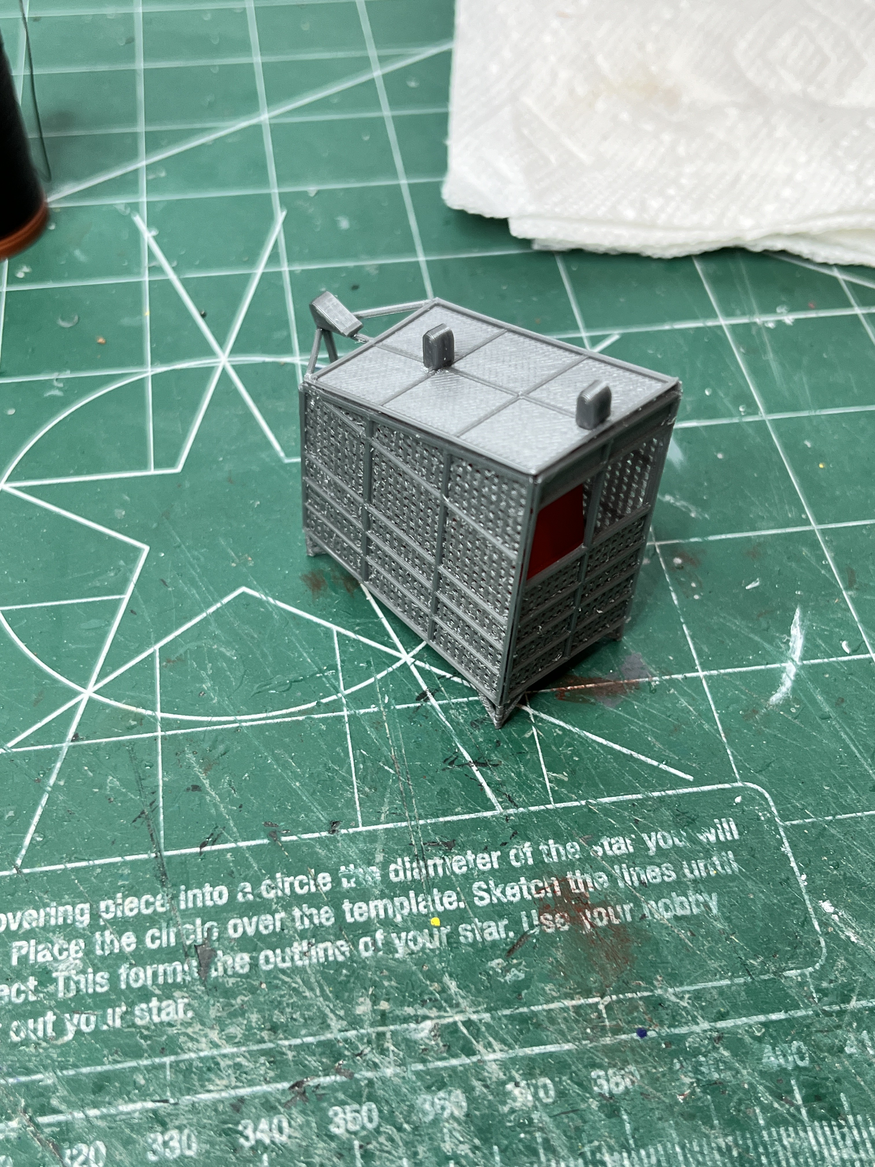
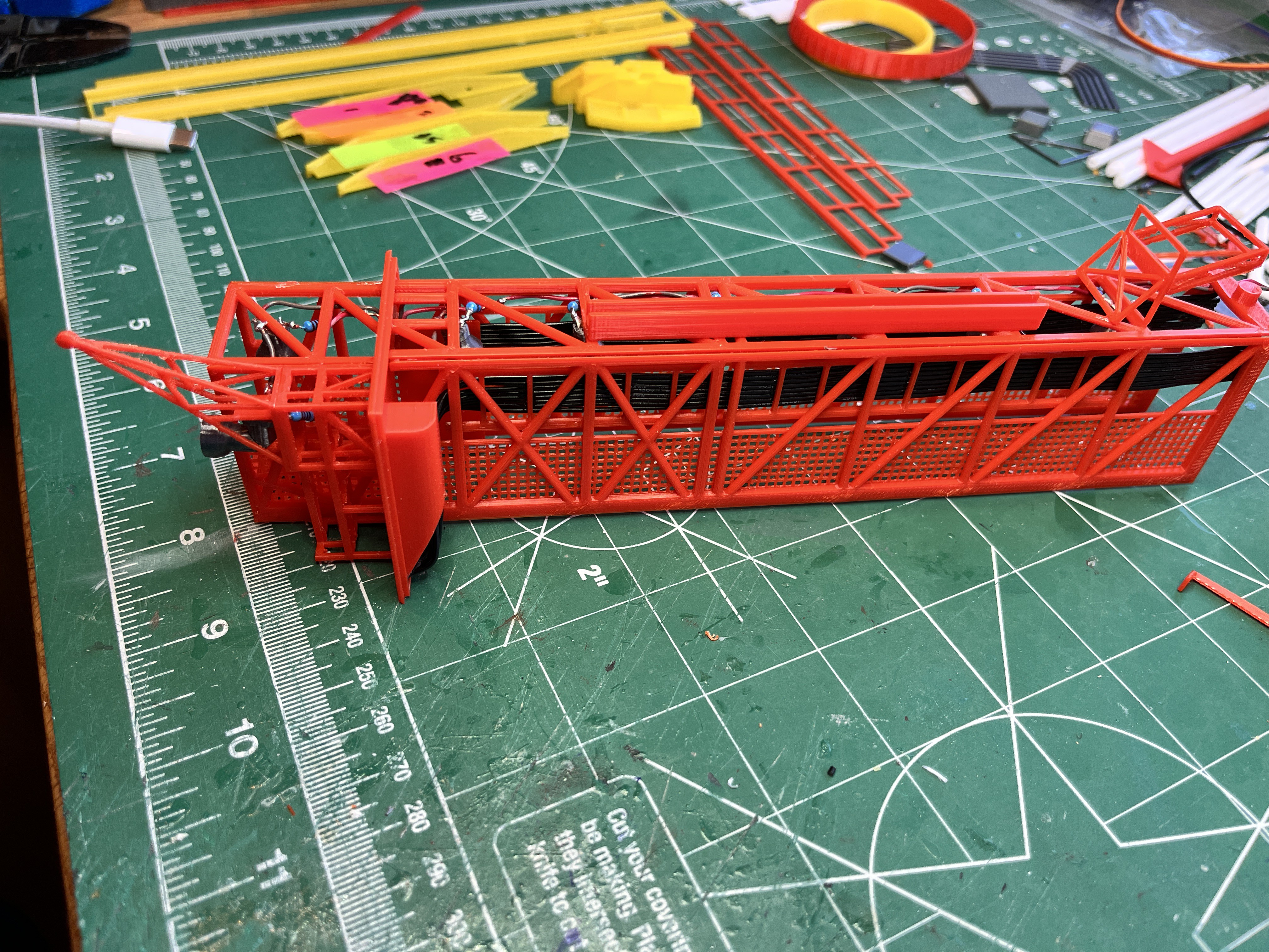
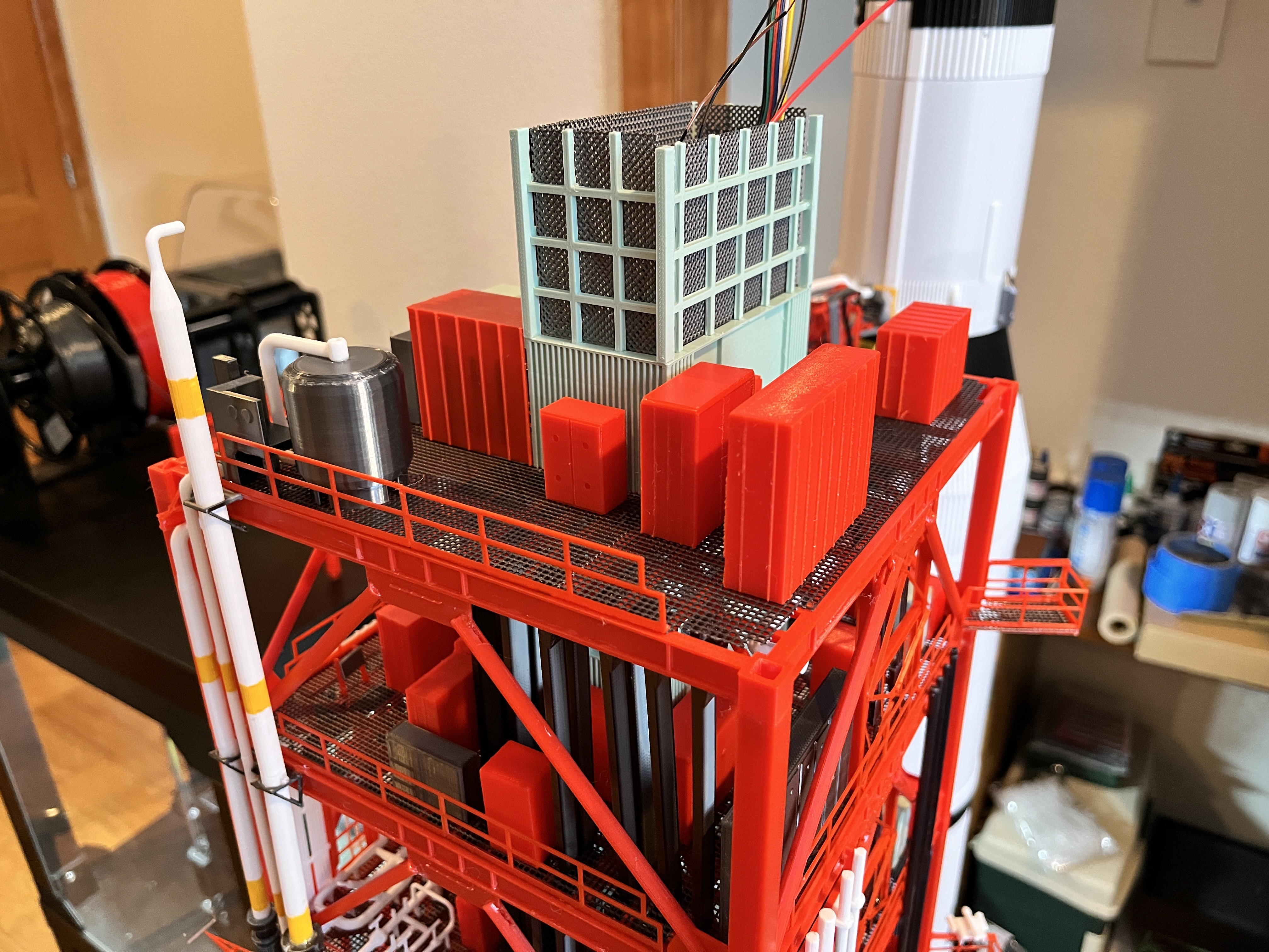
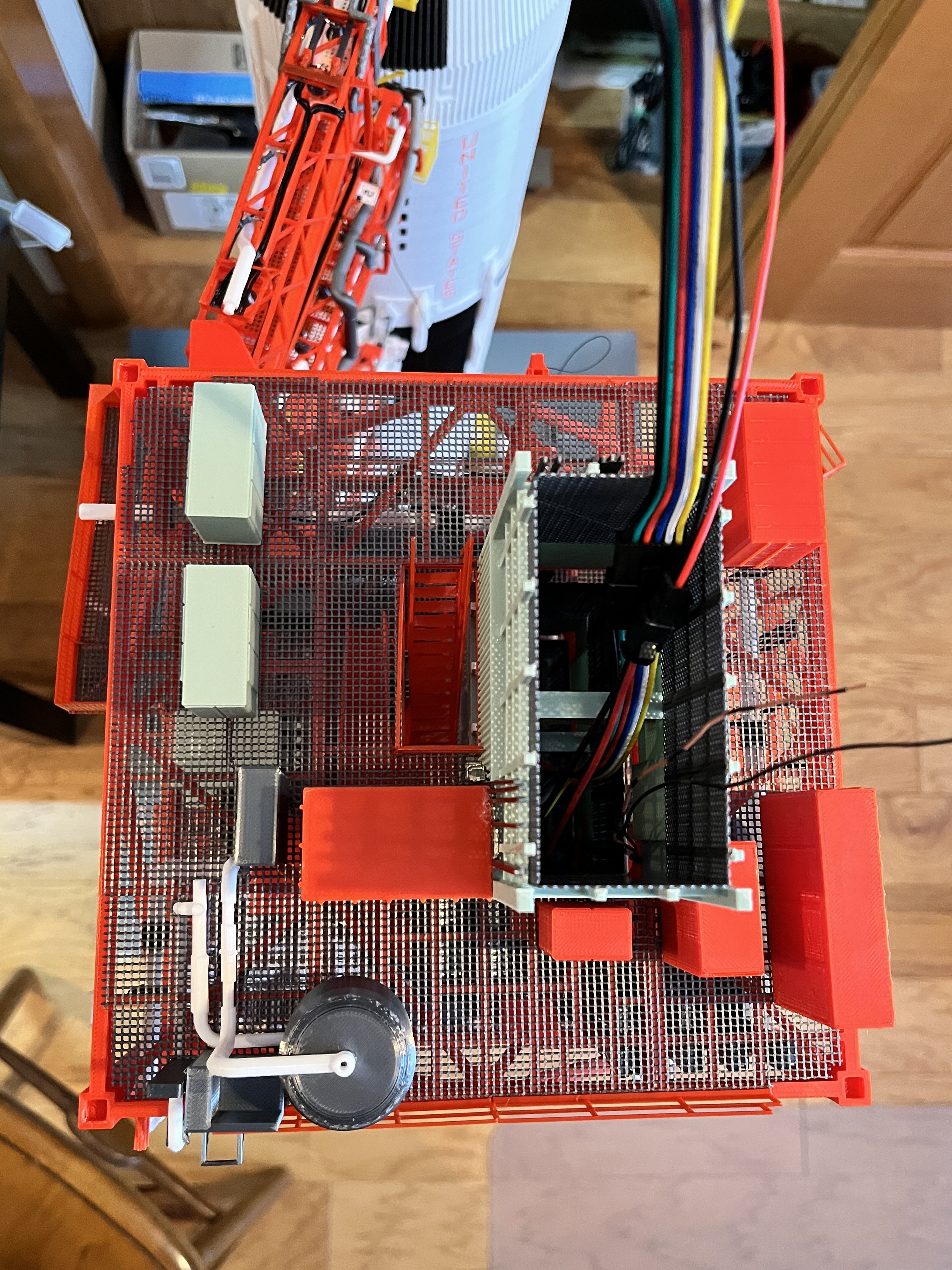
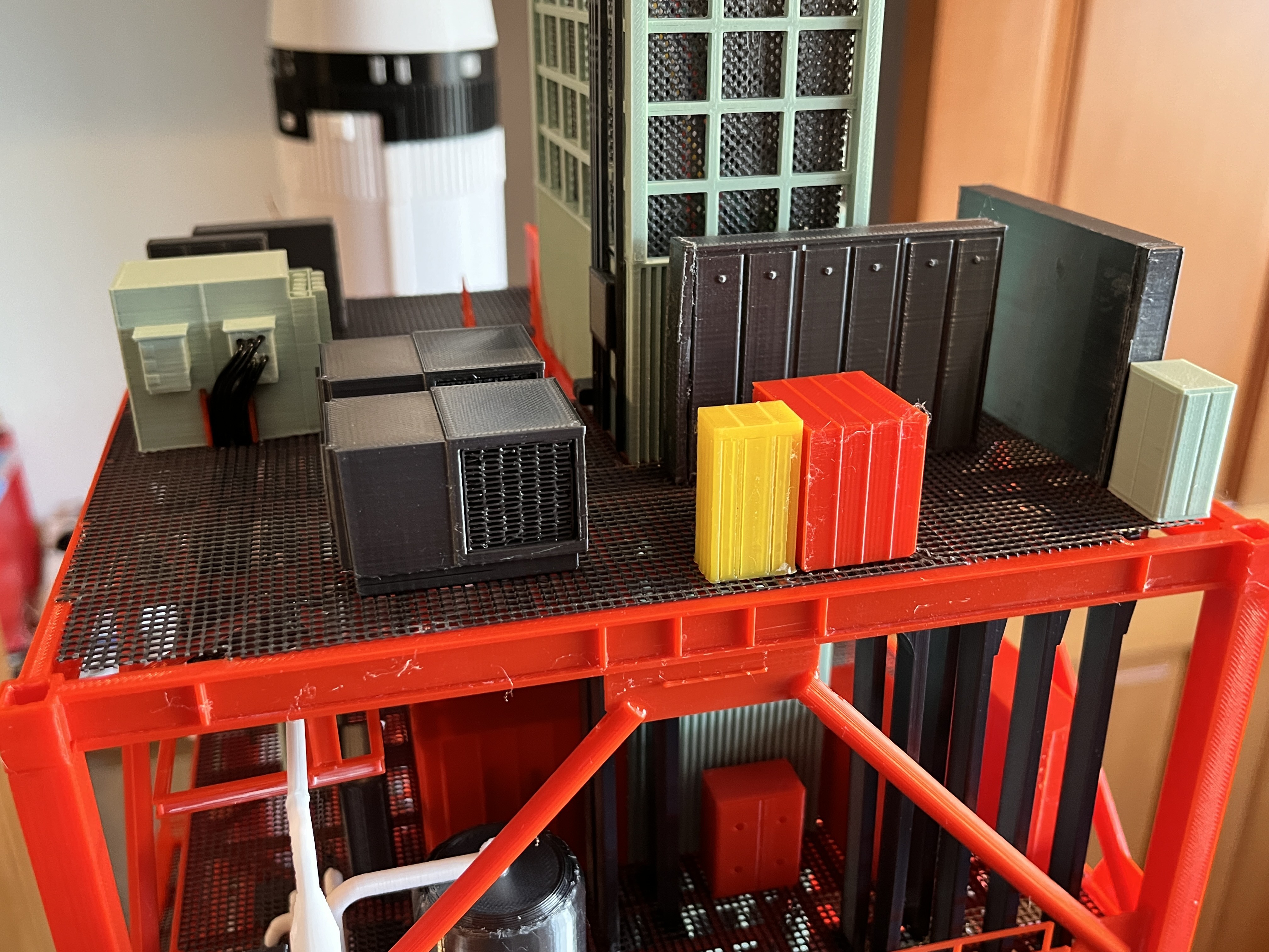
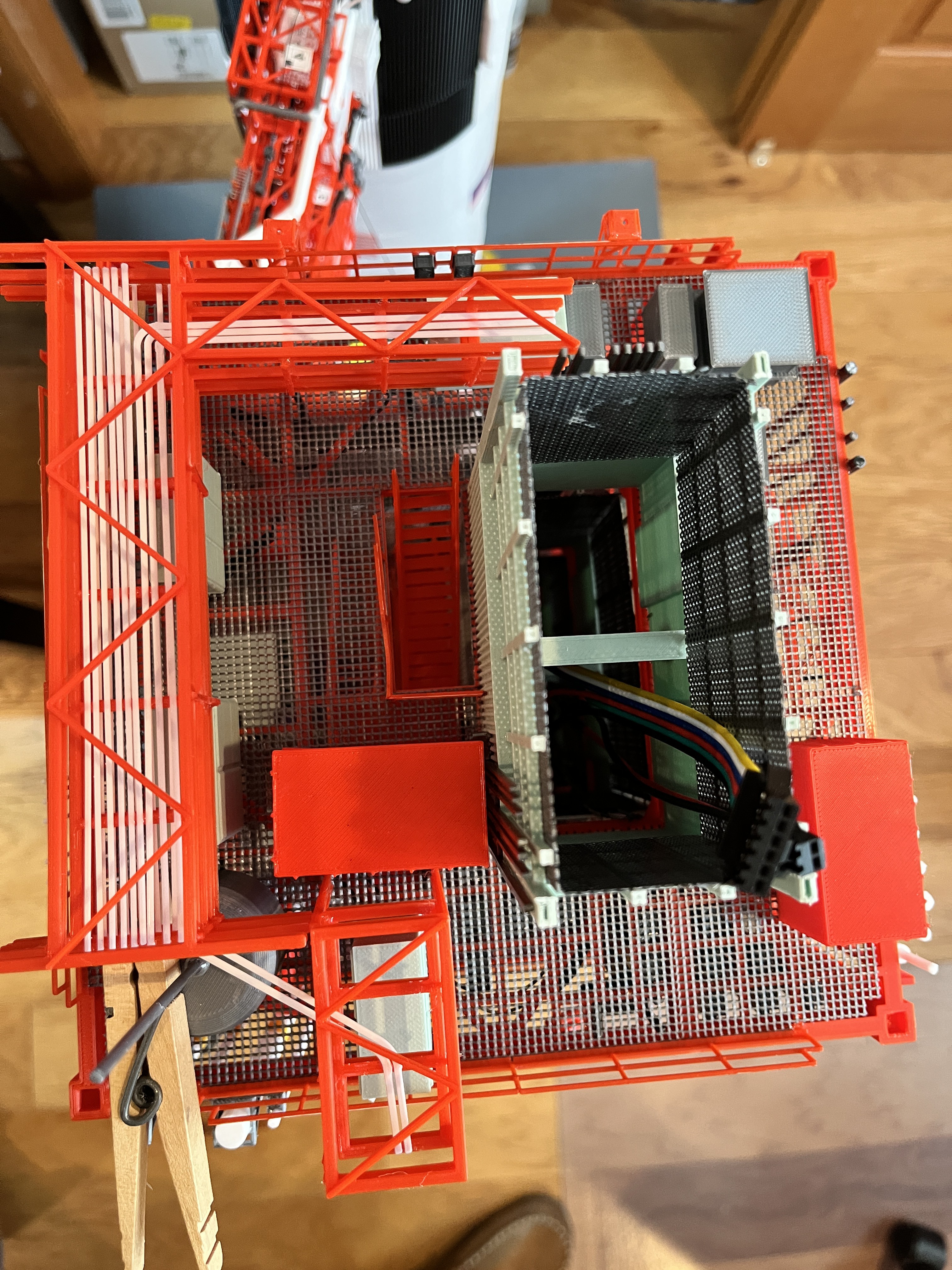
- Equipment - Complete
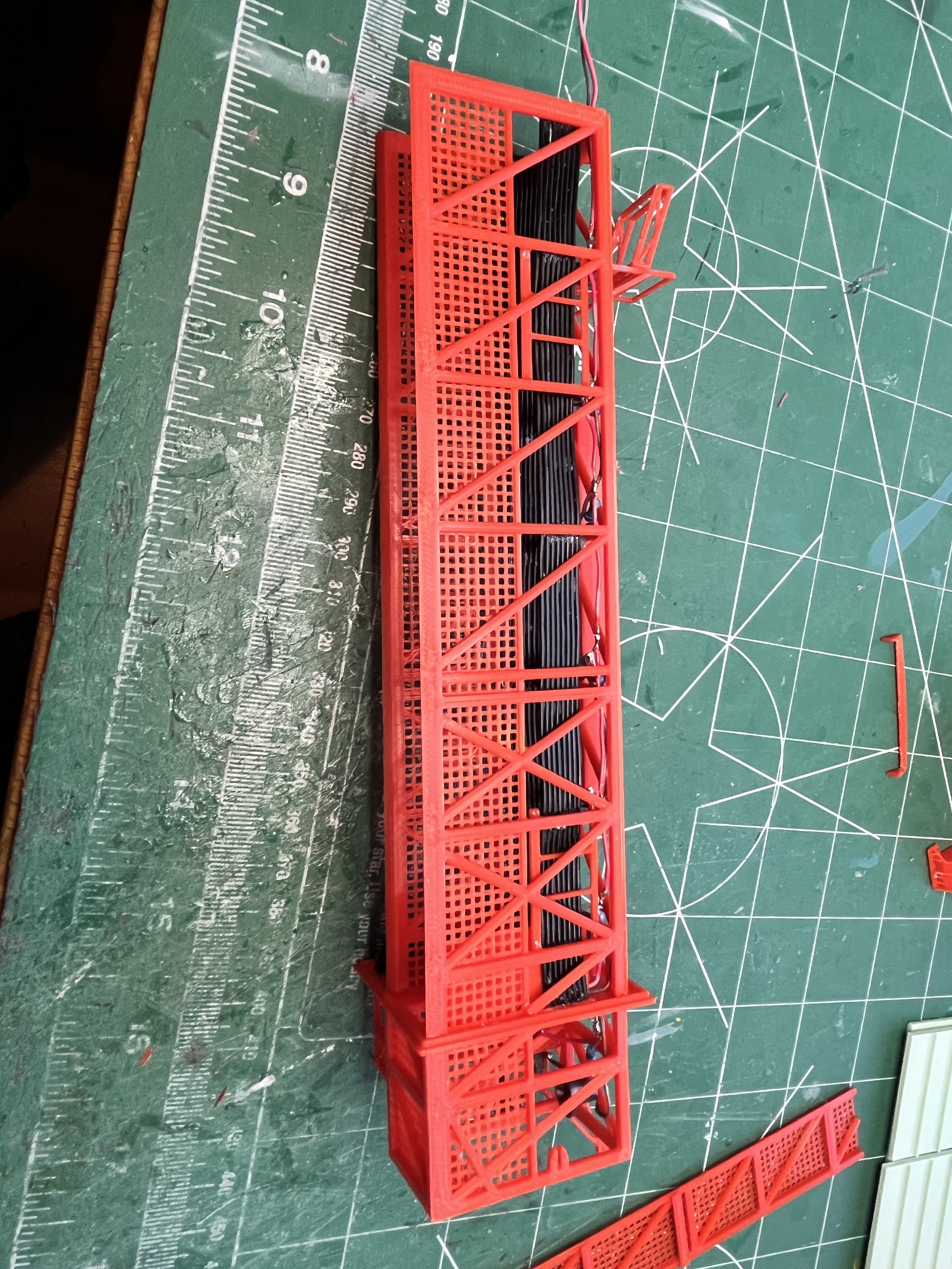
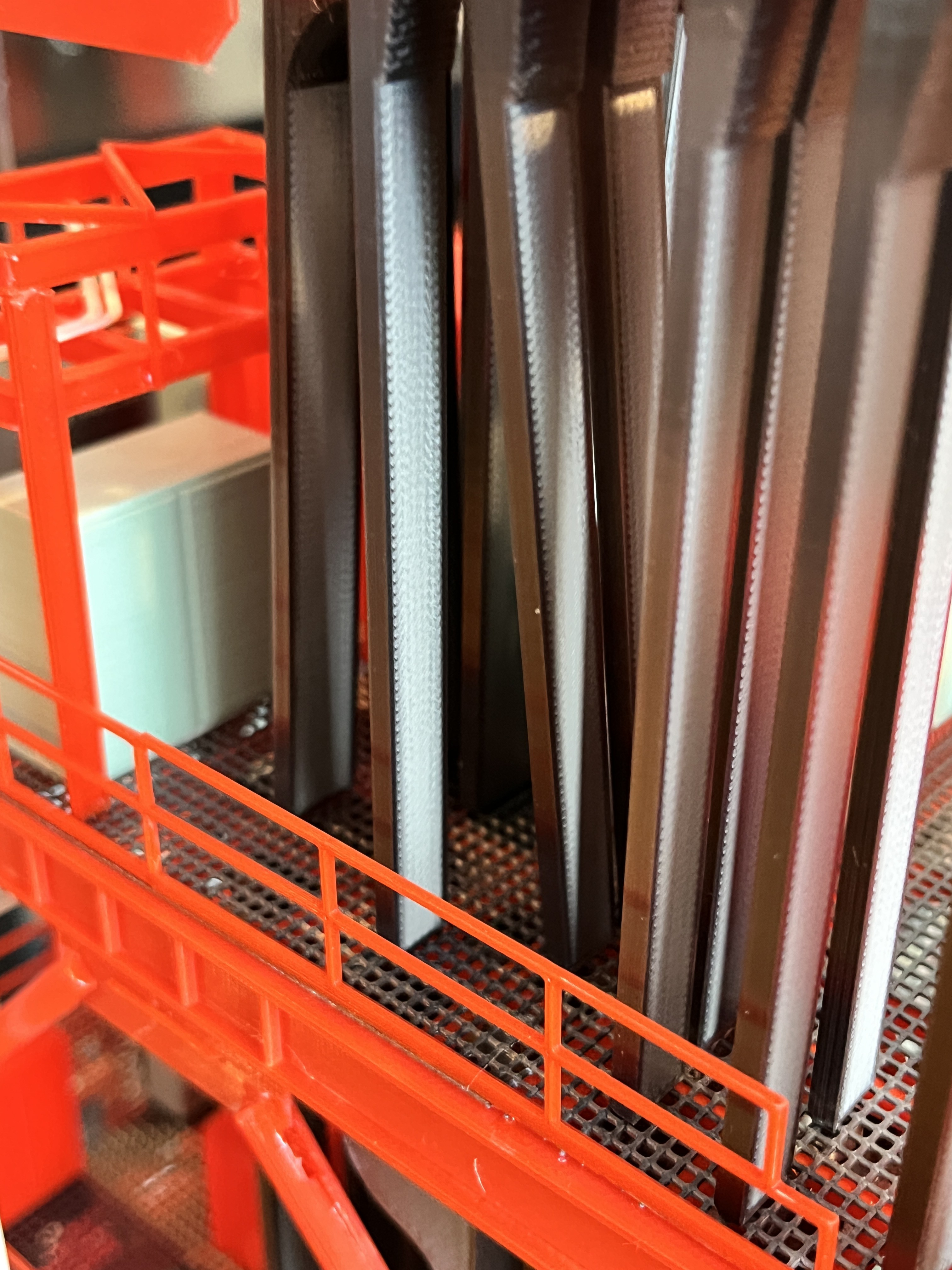
- Cable Trays - Complete
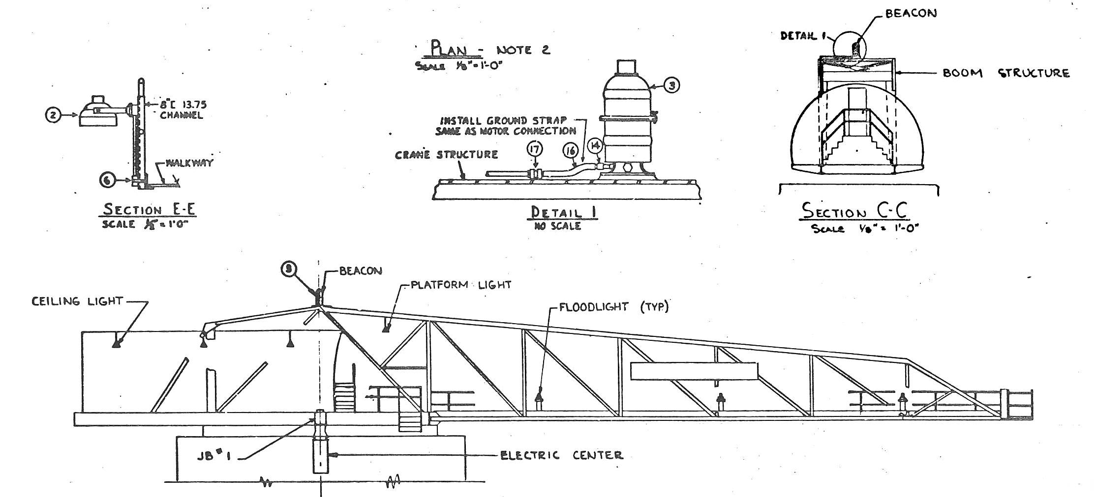
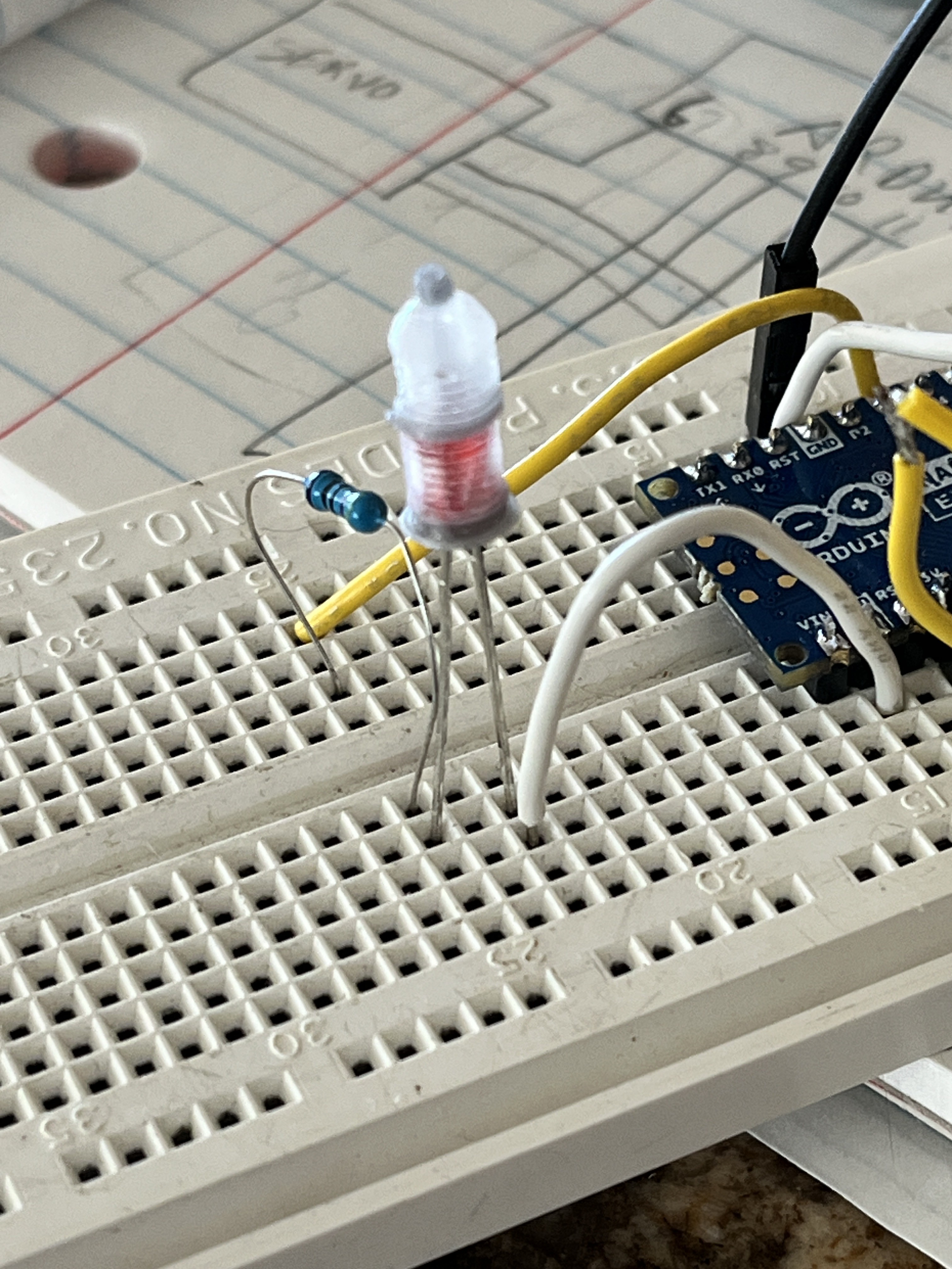
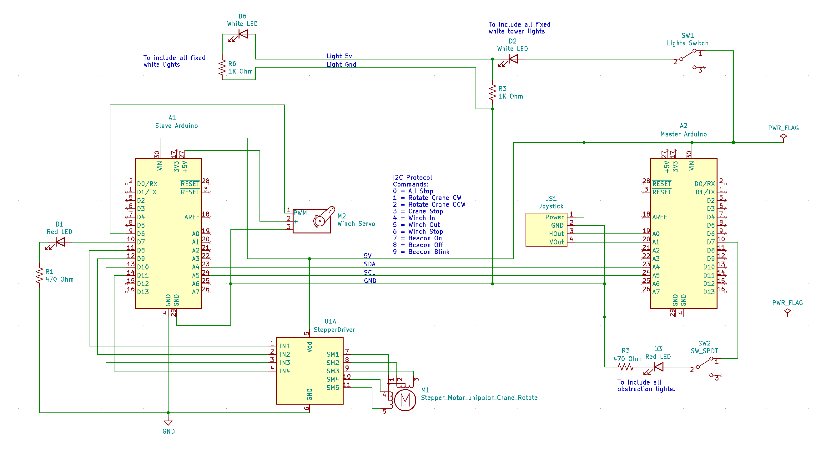
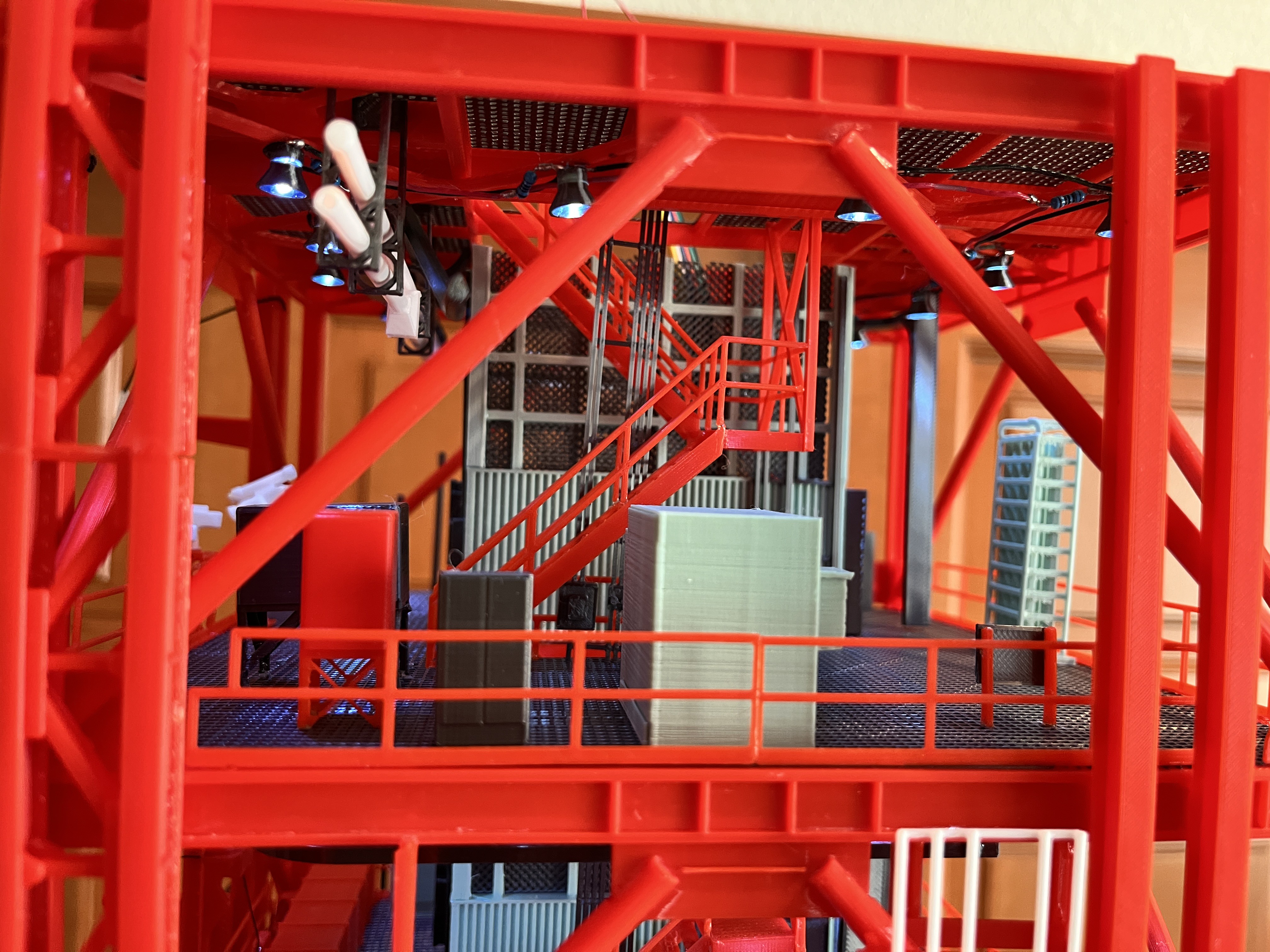
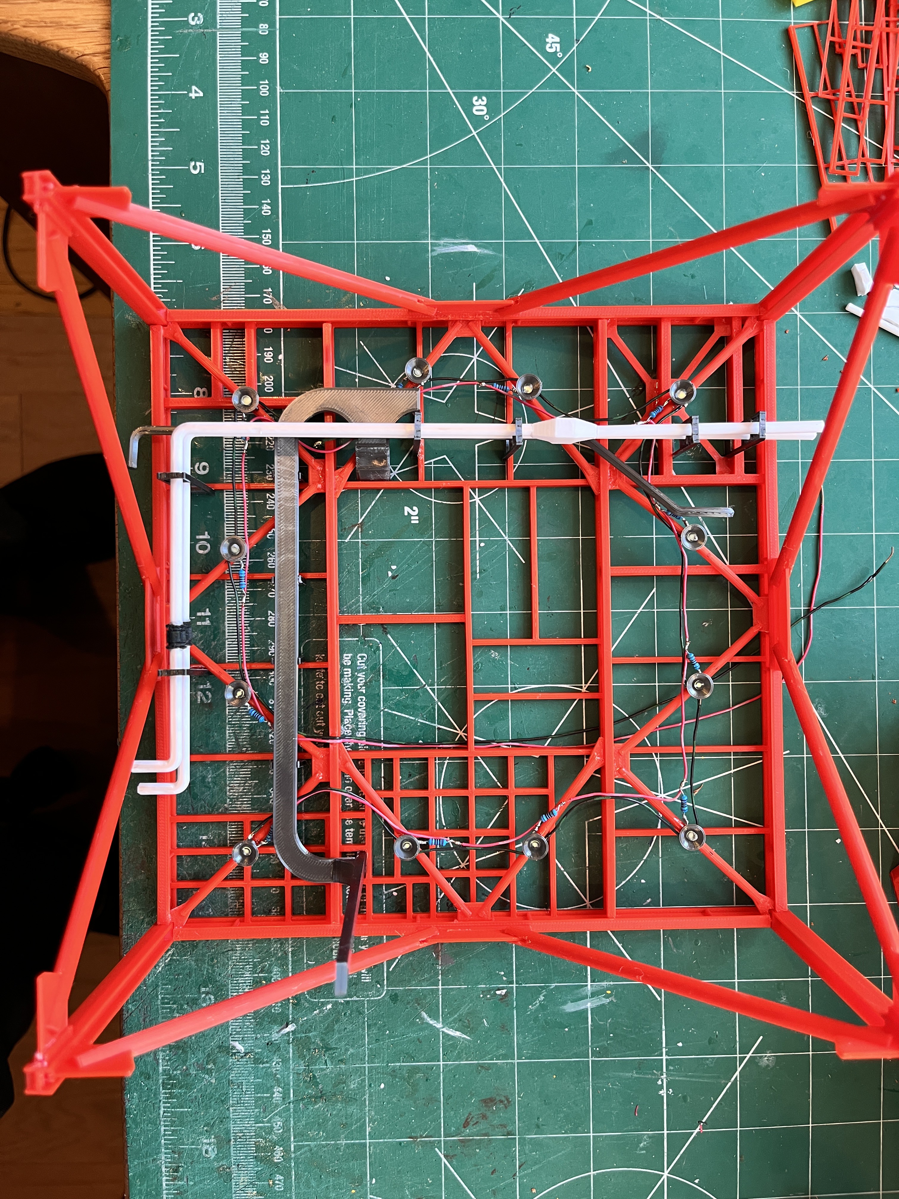
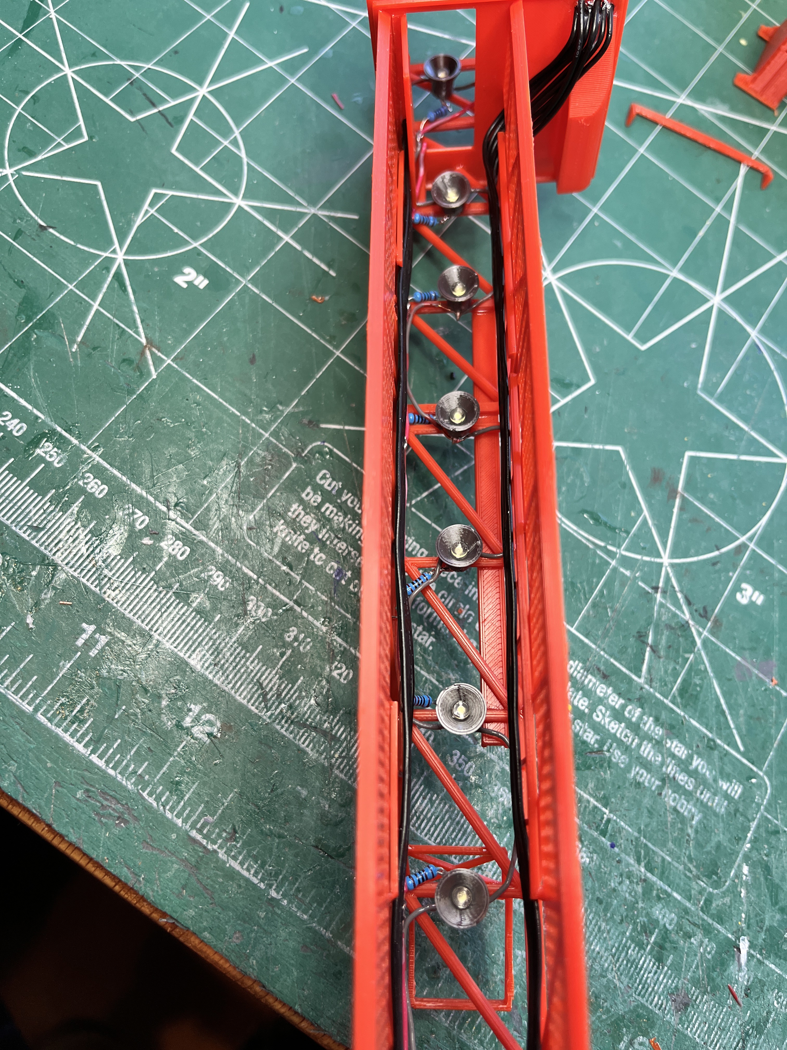
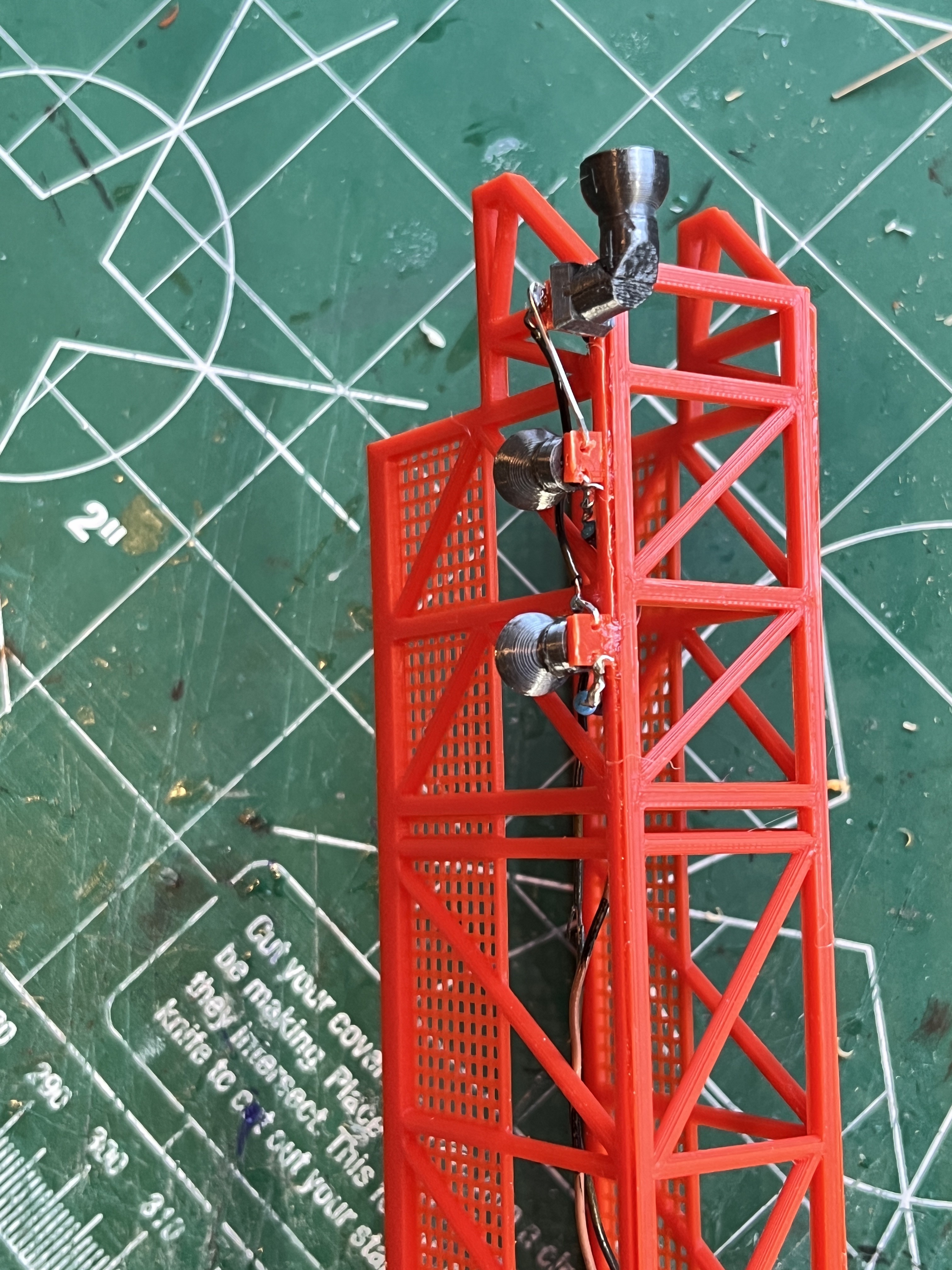
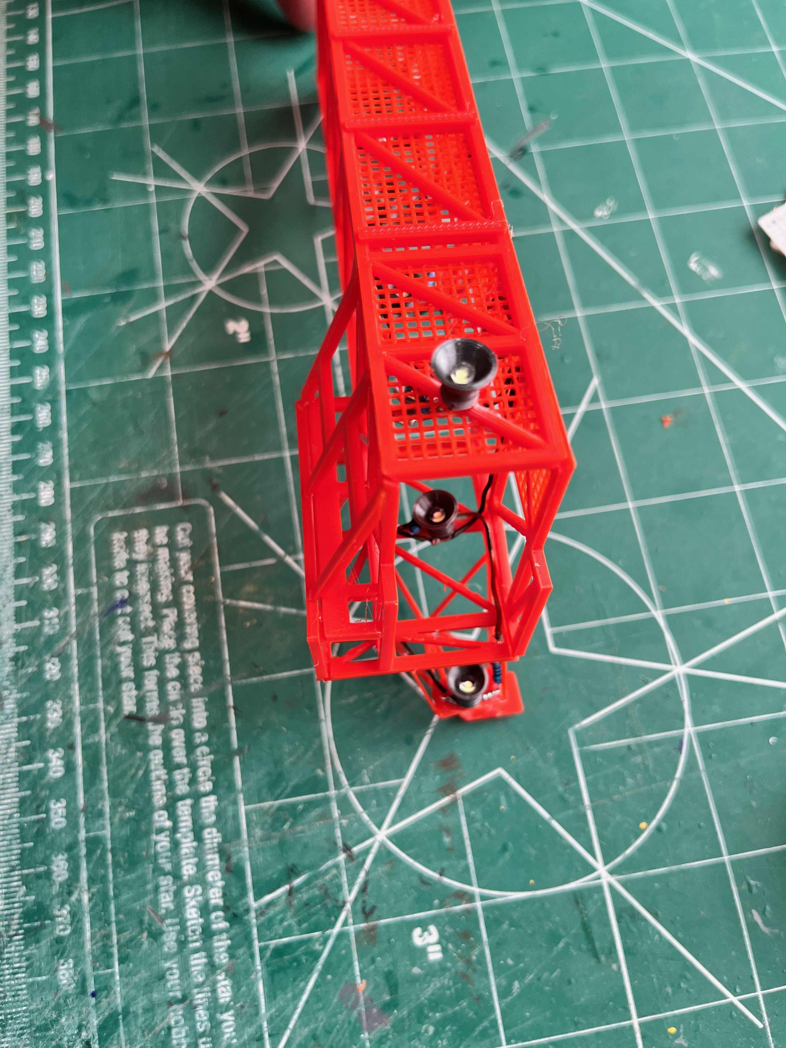
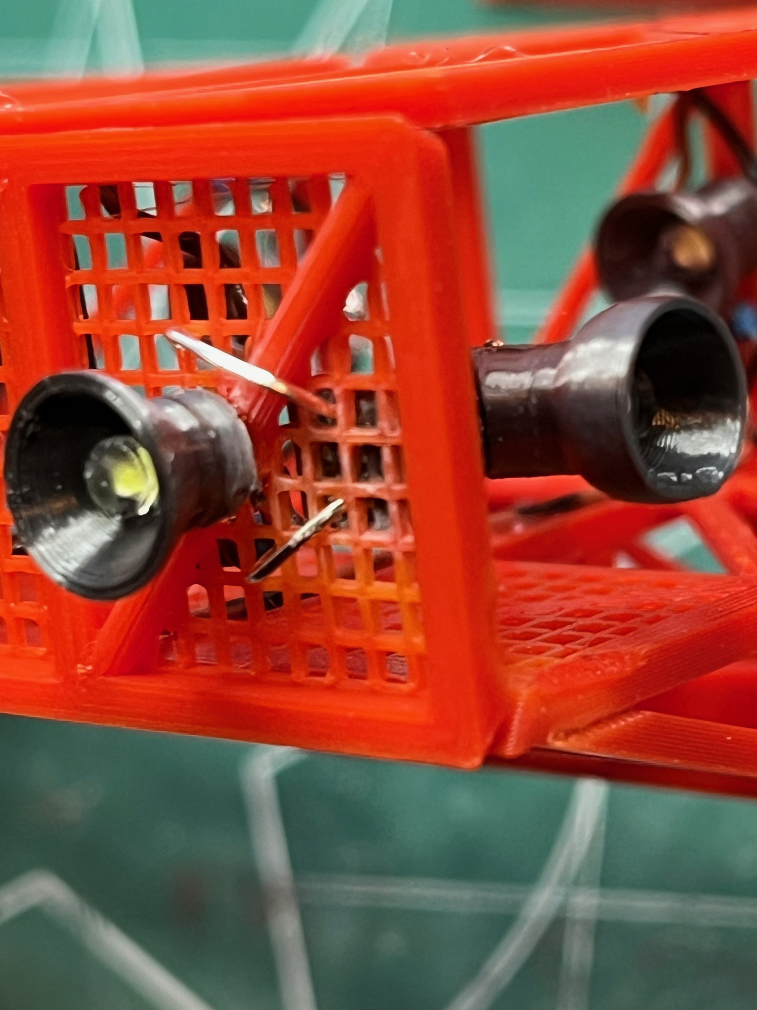
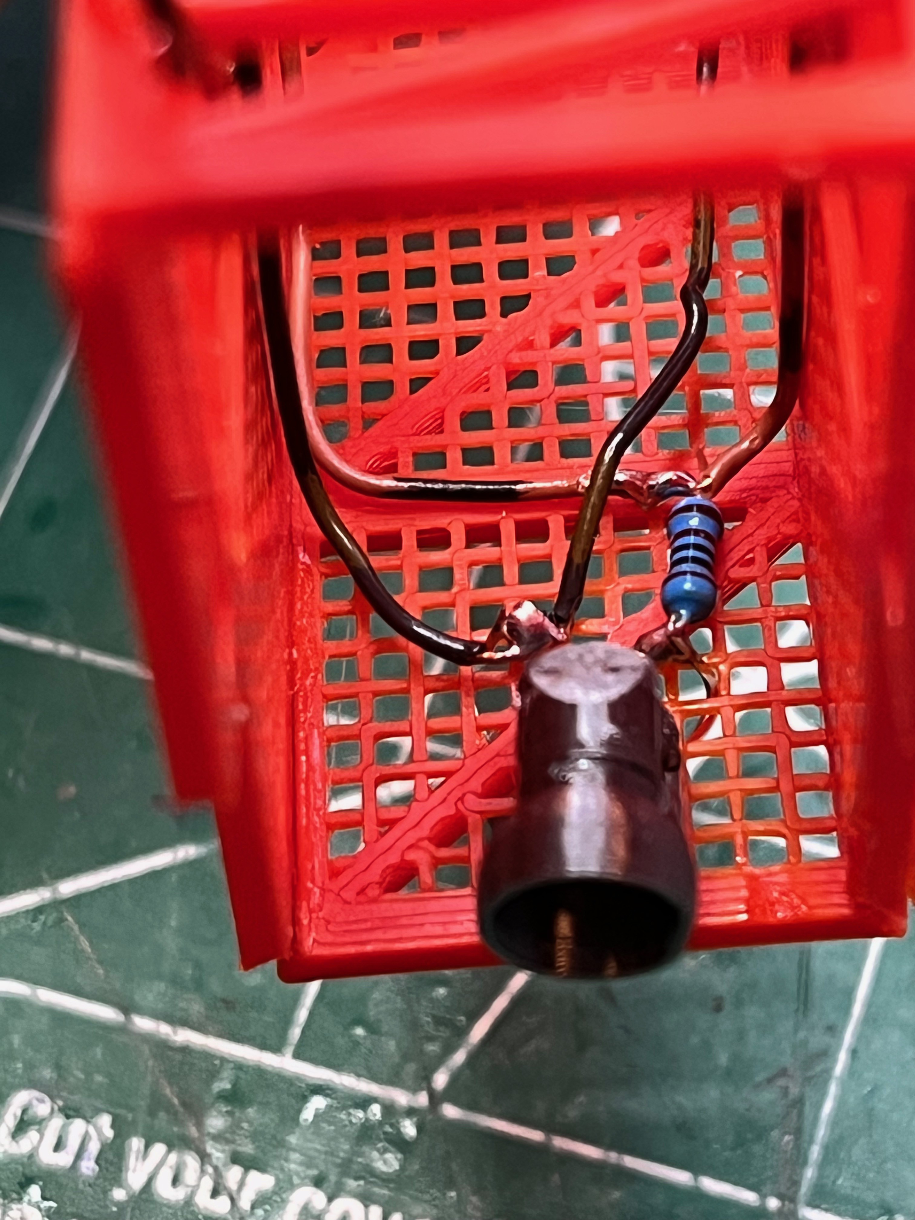
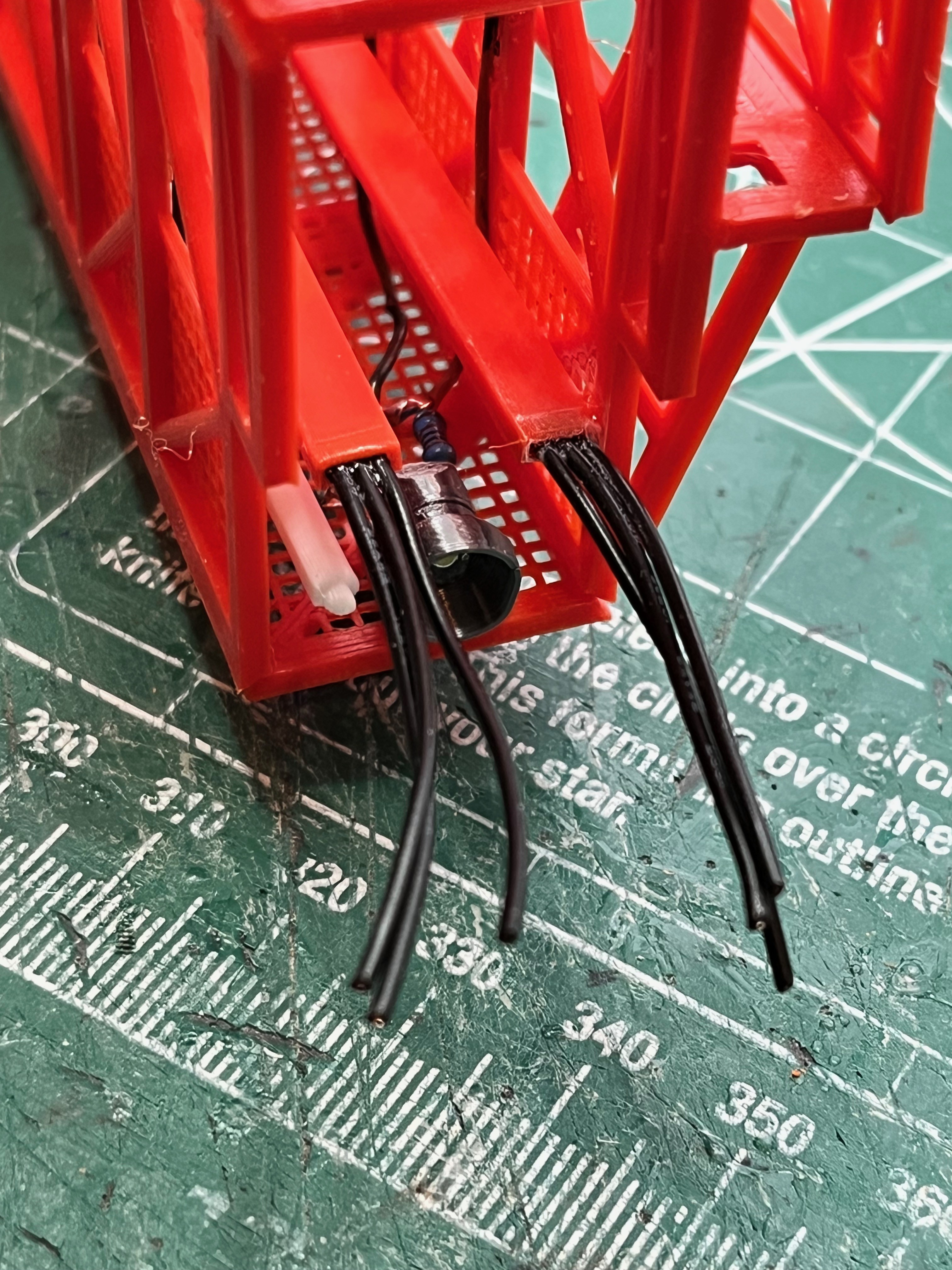
- Lights - Complete
- Cameras - Complete
- Anemometer - Complete
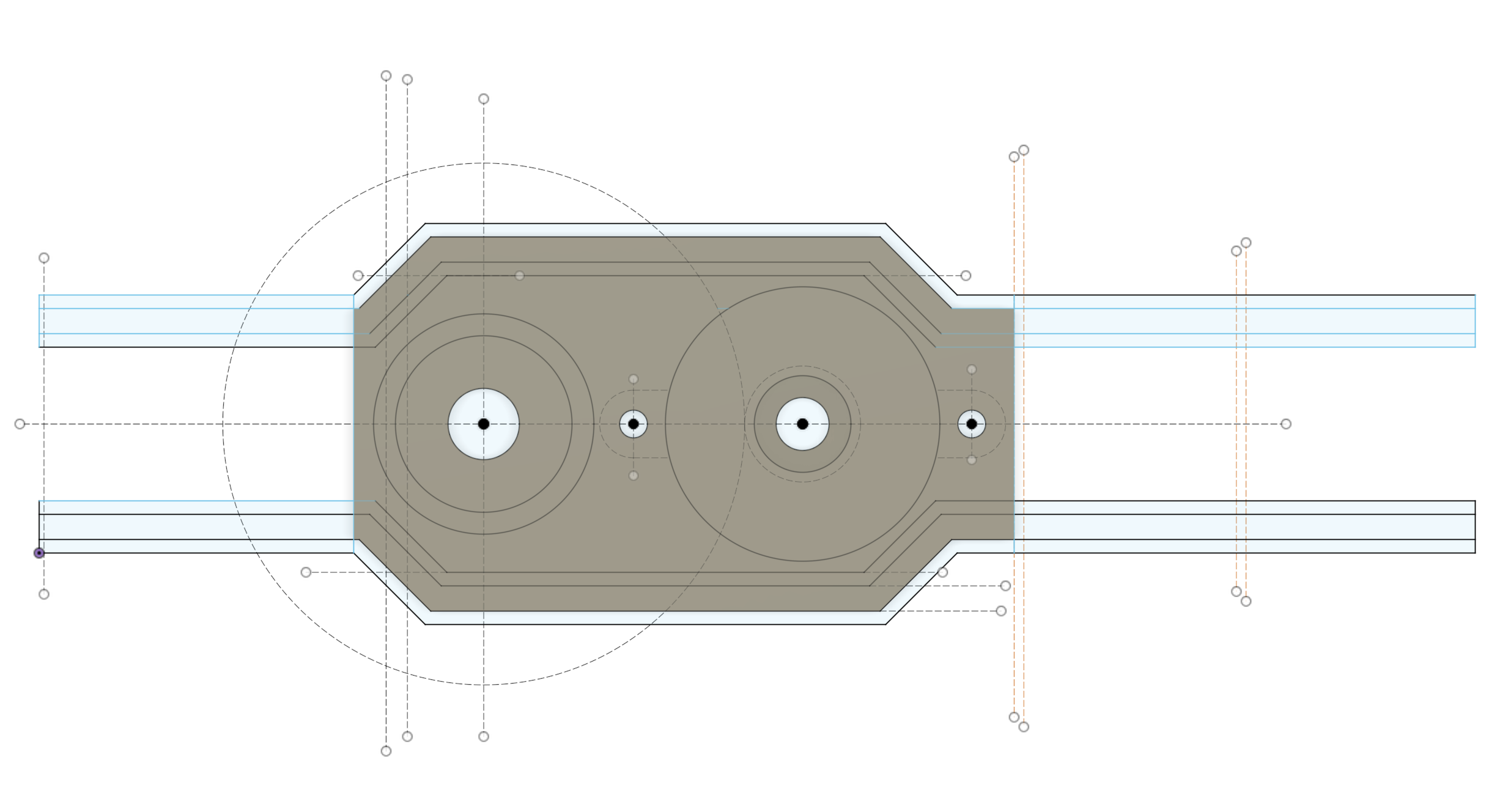
- Motor Housing - Complete
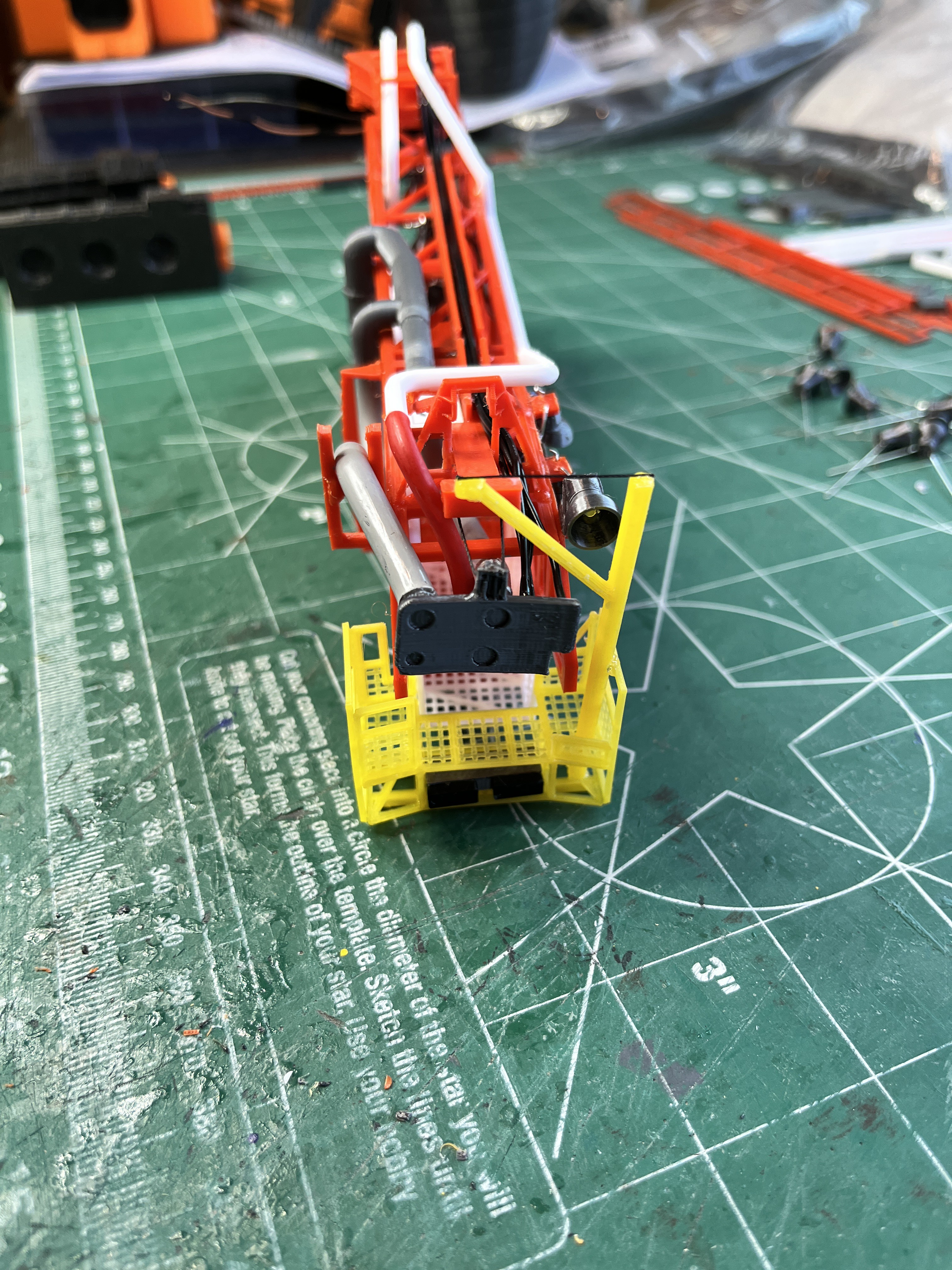
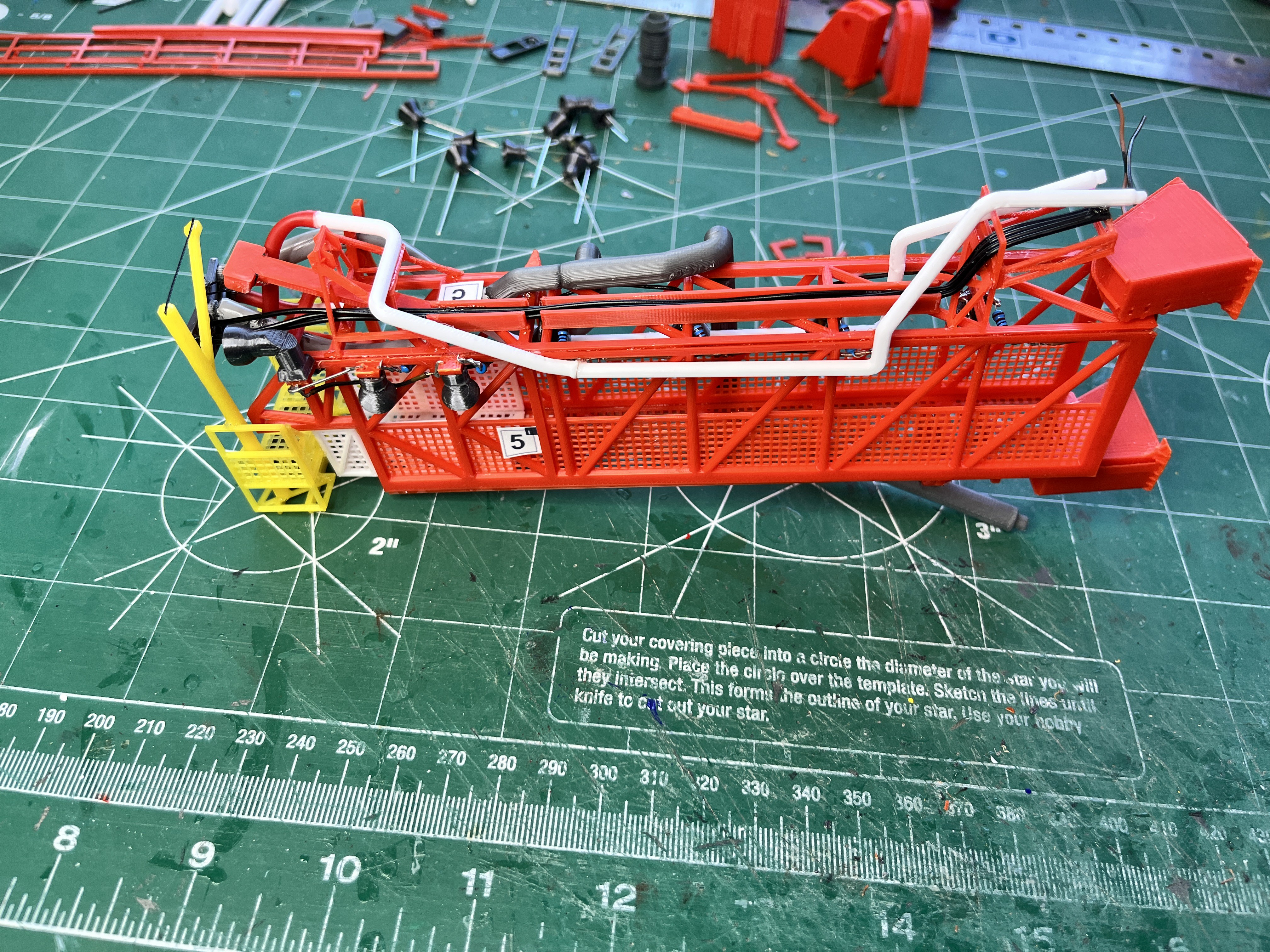
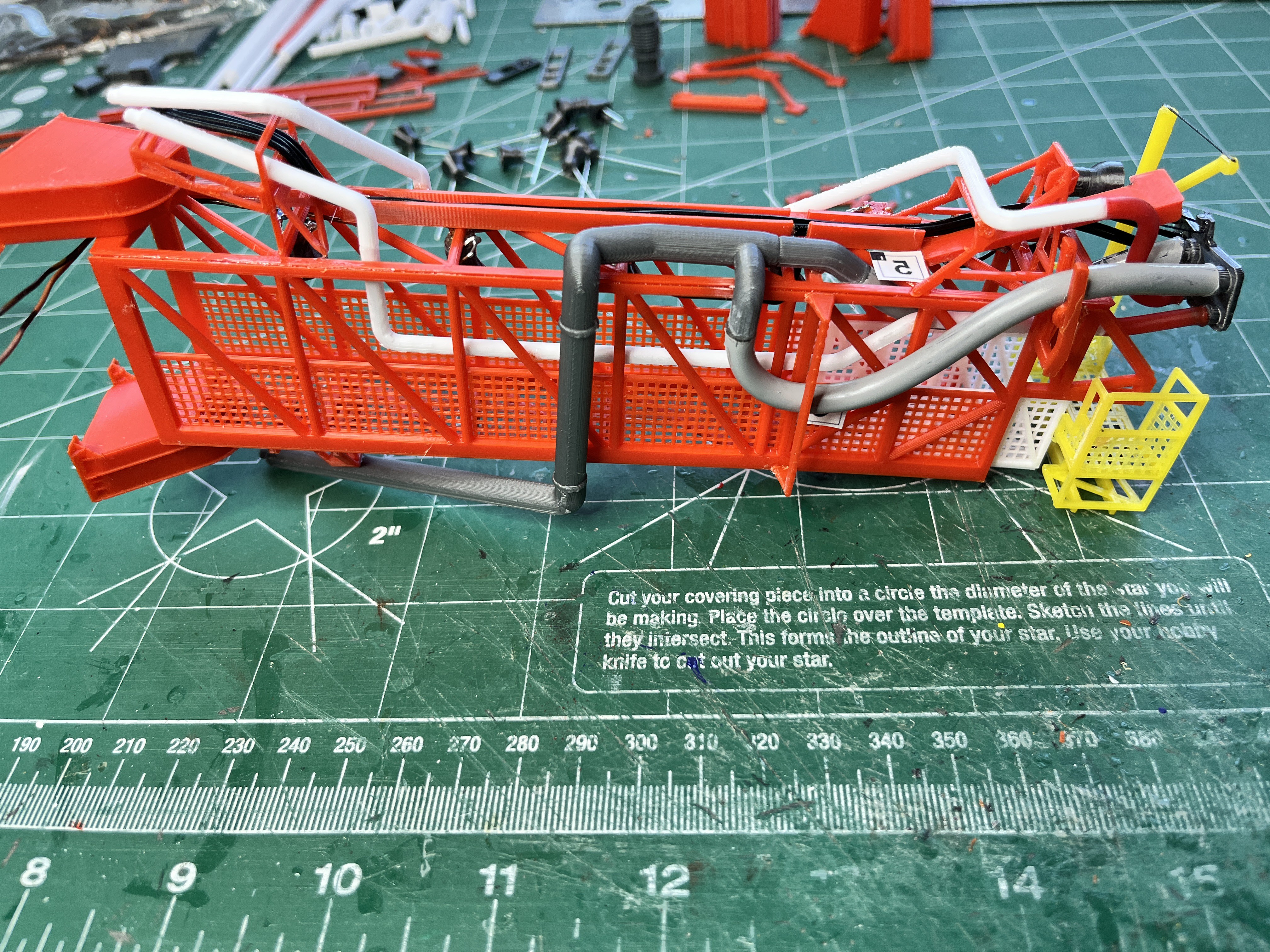
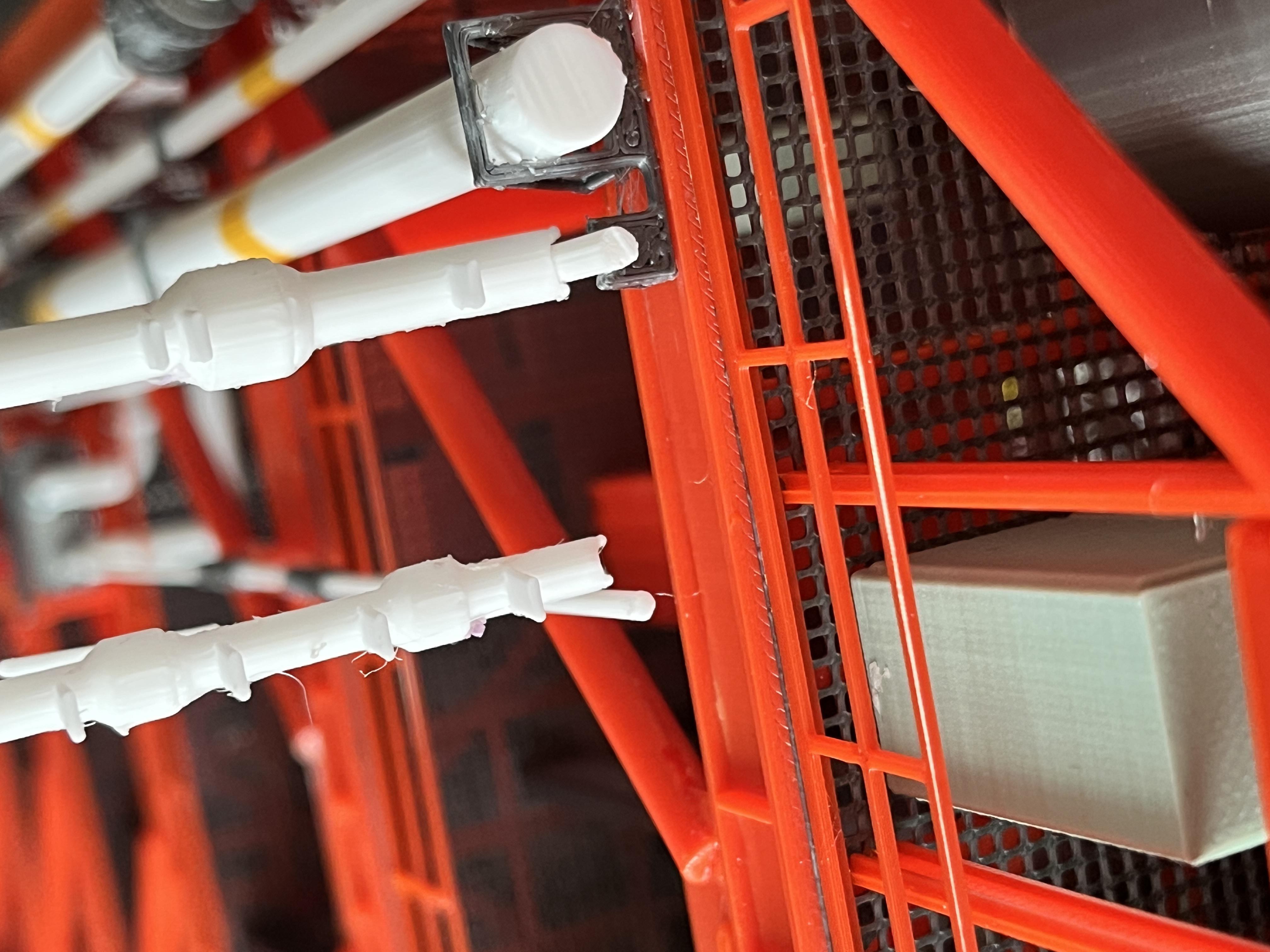
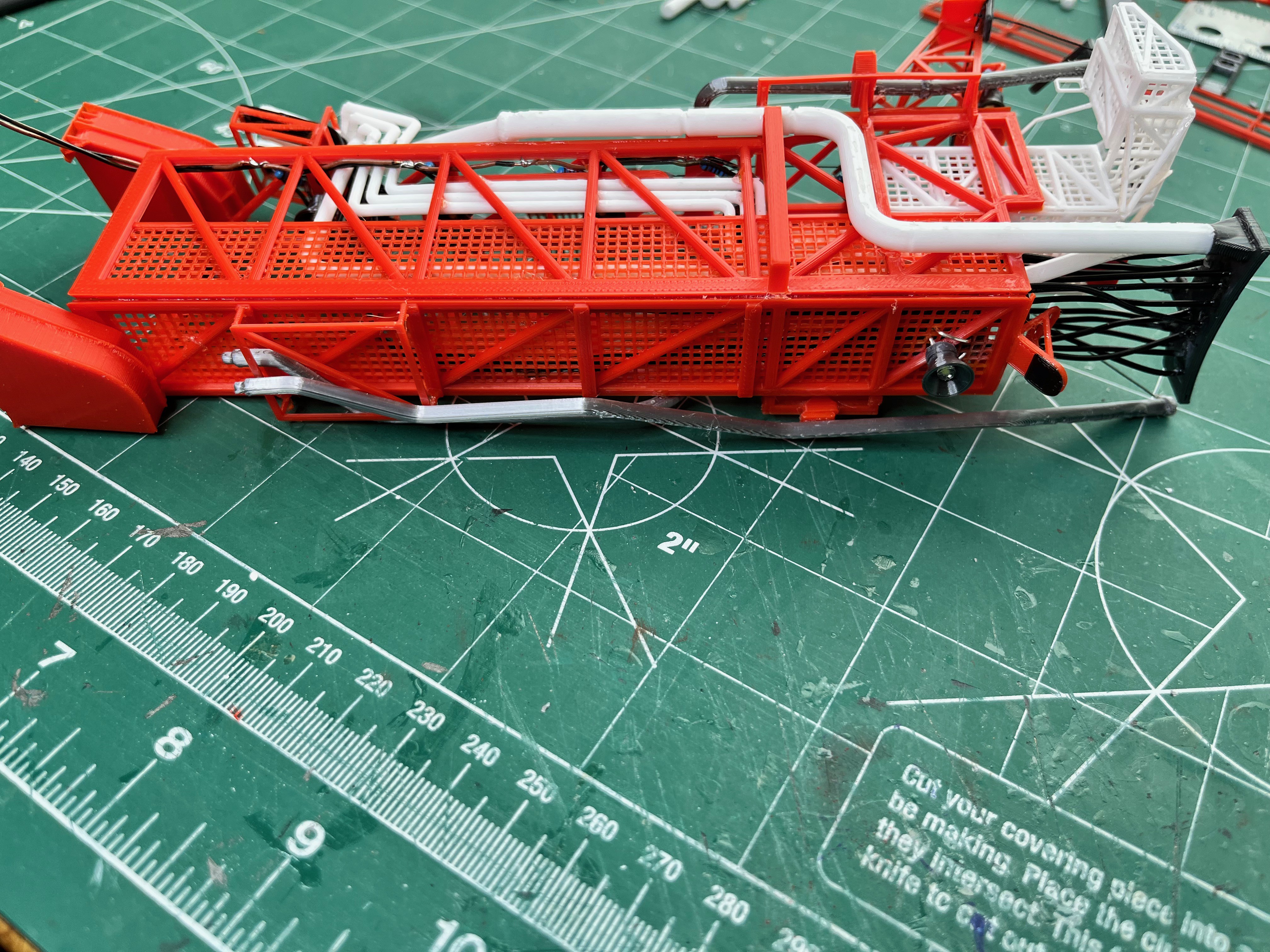
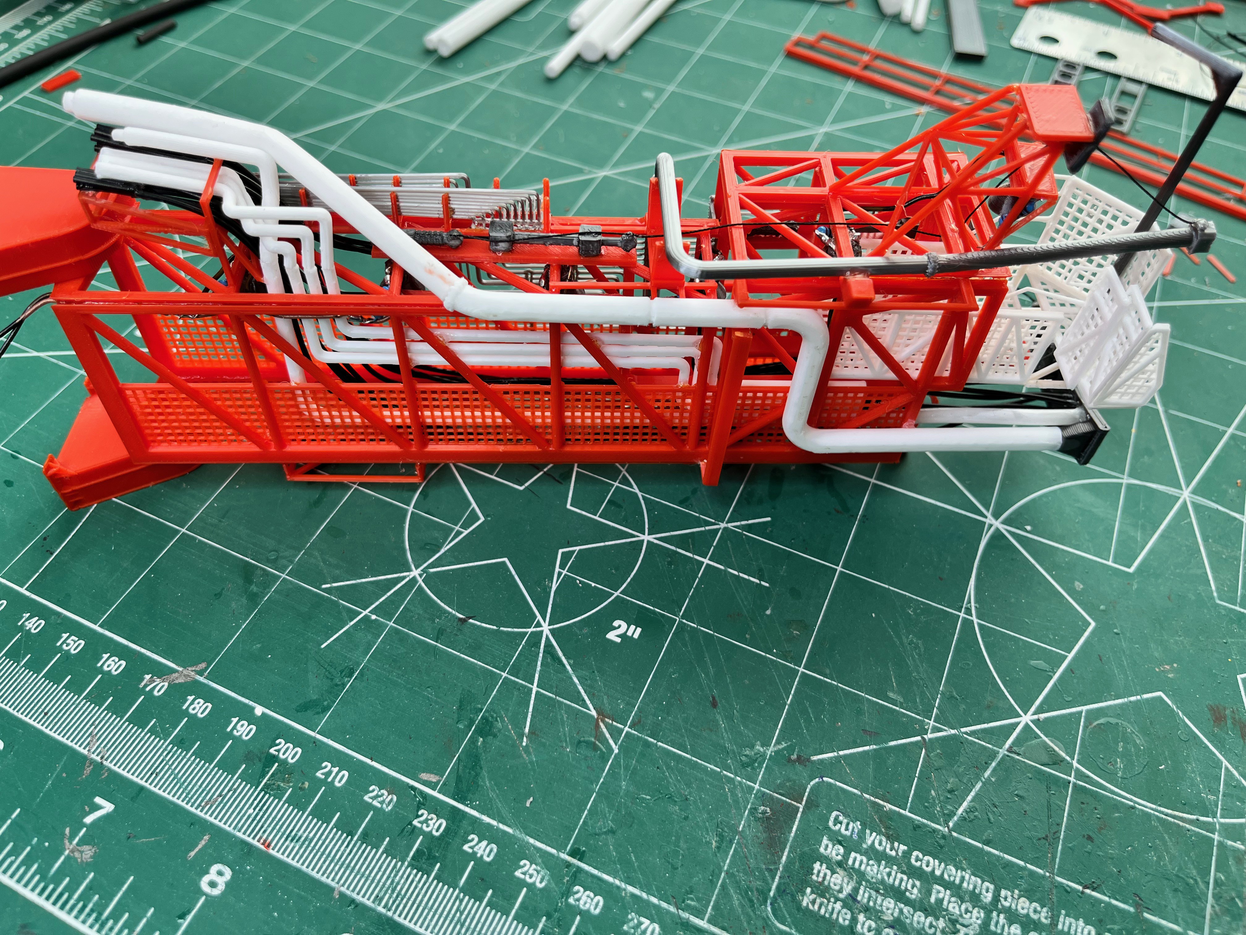
- Piping Side 1 - Complete
- Piping Side 2 - Complete
- Piping Side 3 - Complete
- Piping Side 4 - Complete
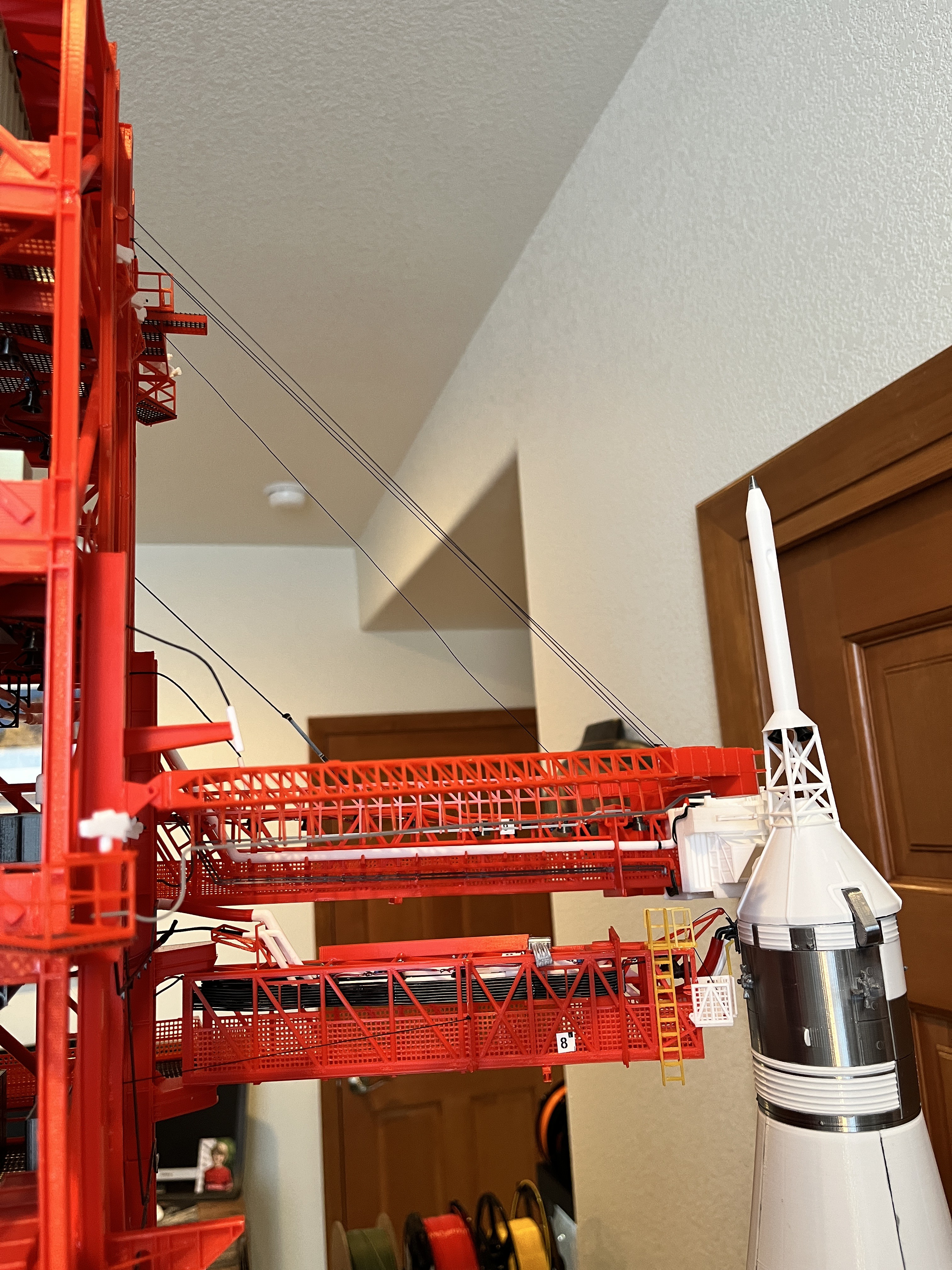
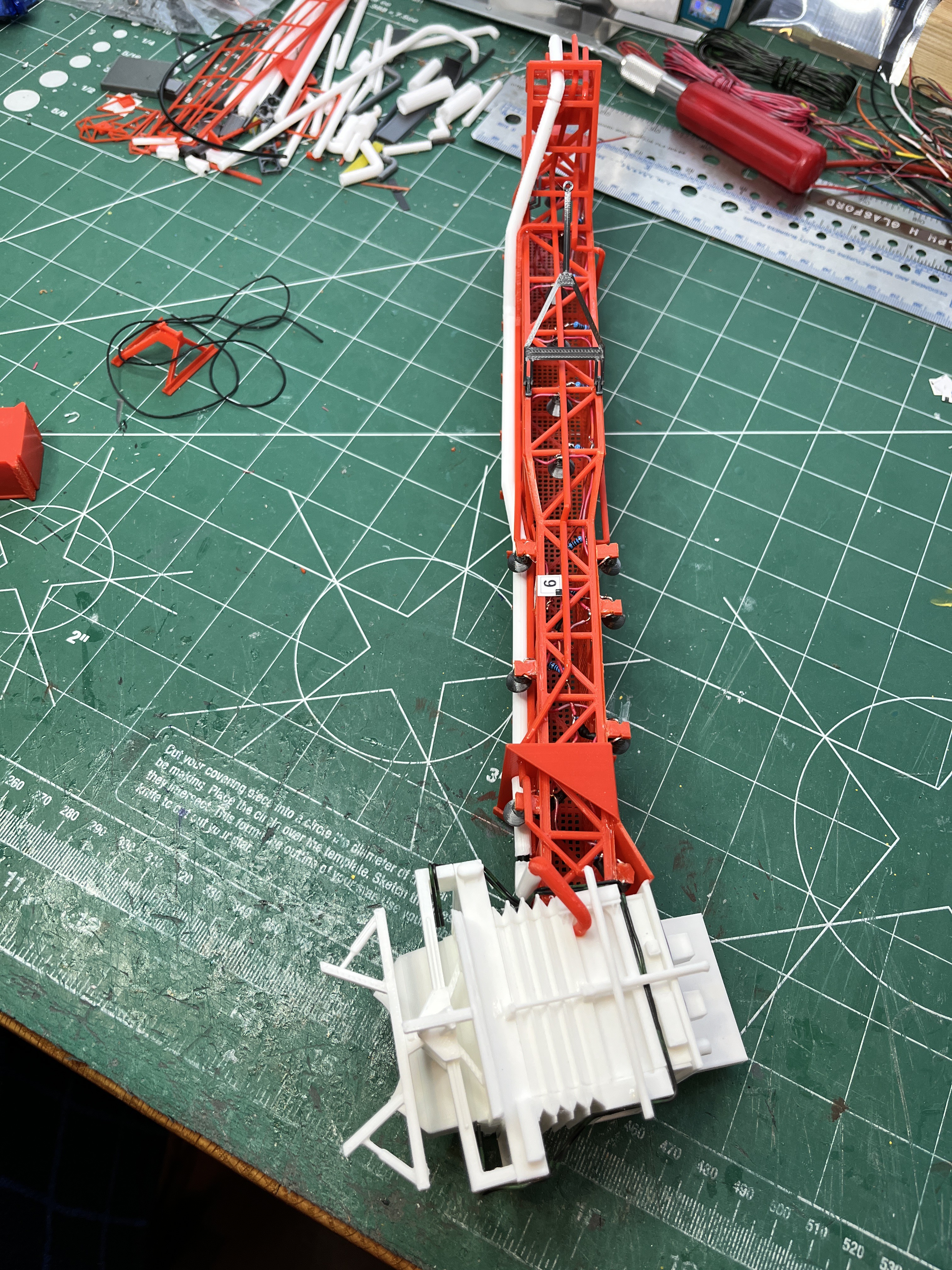
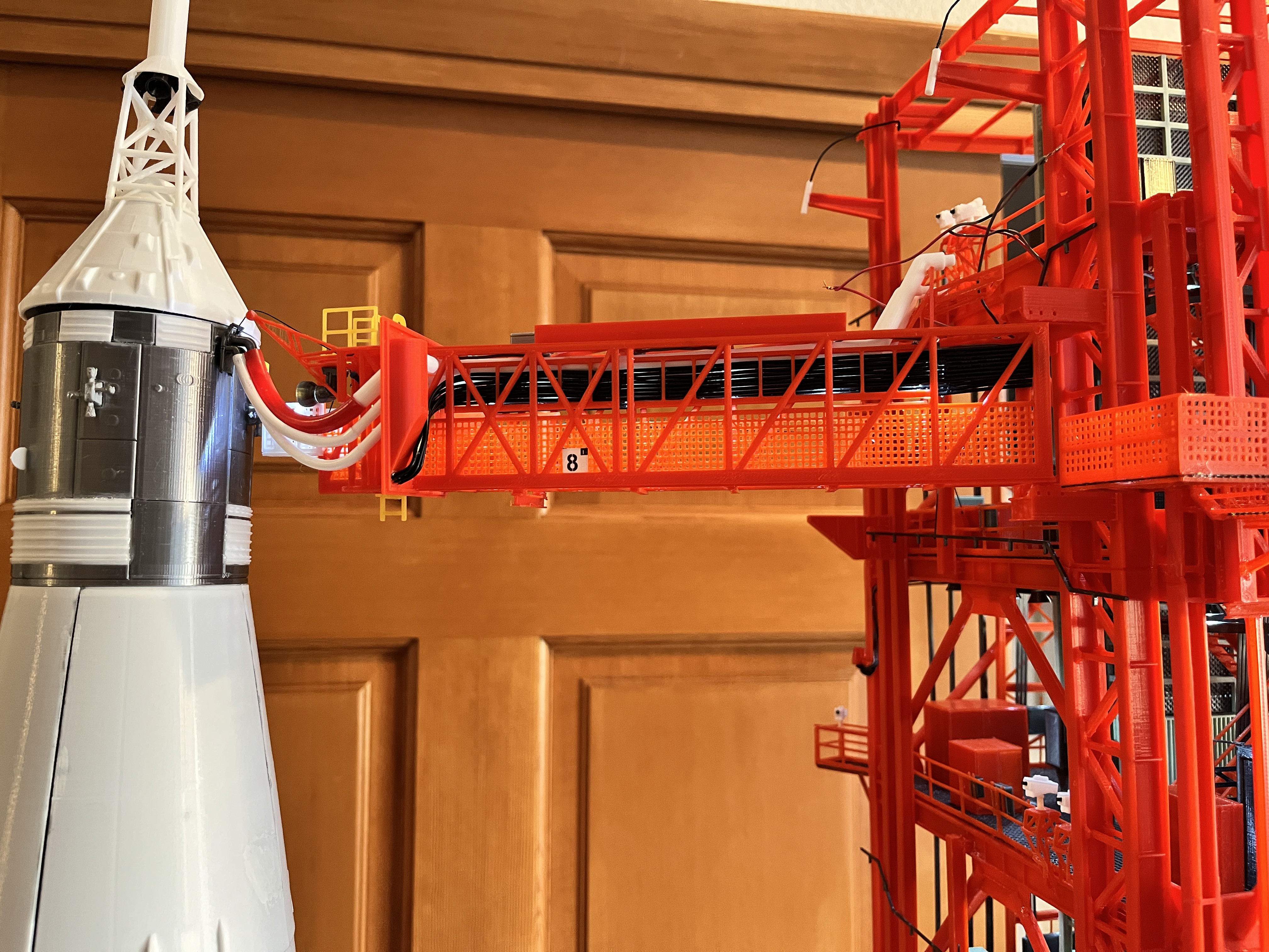
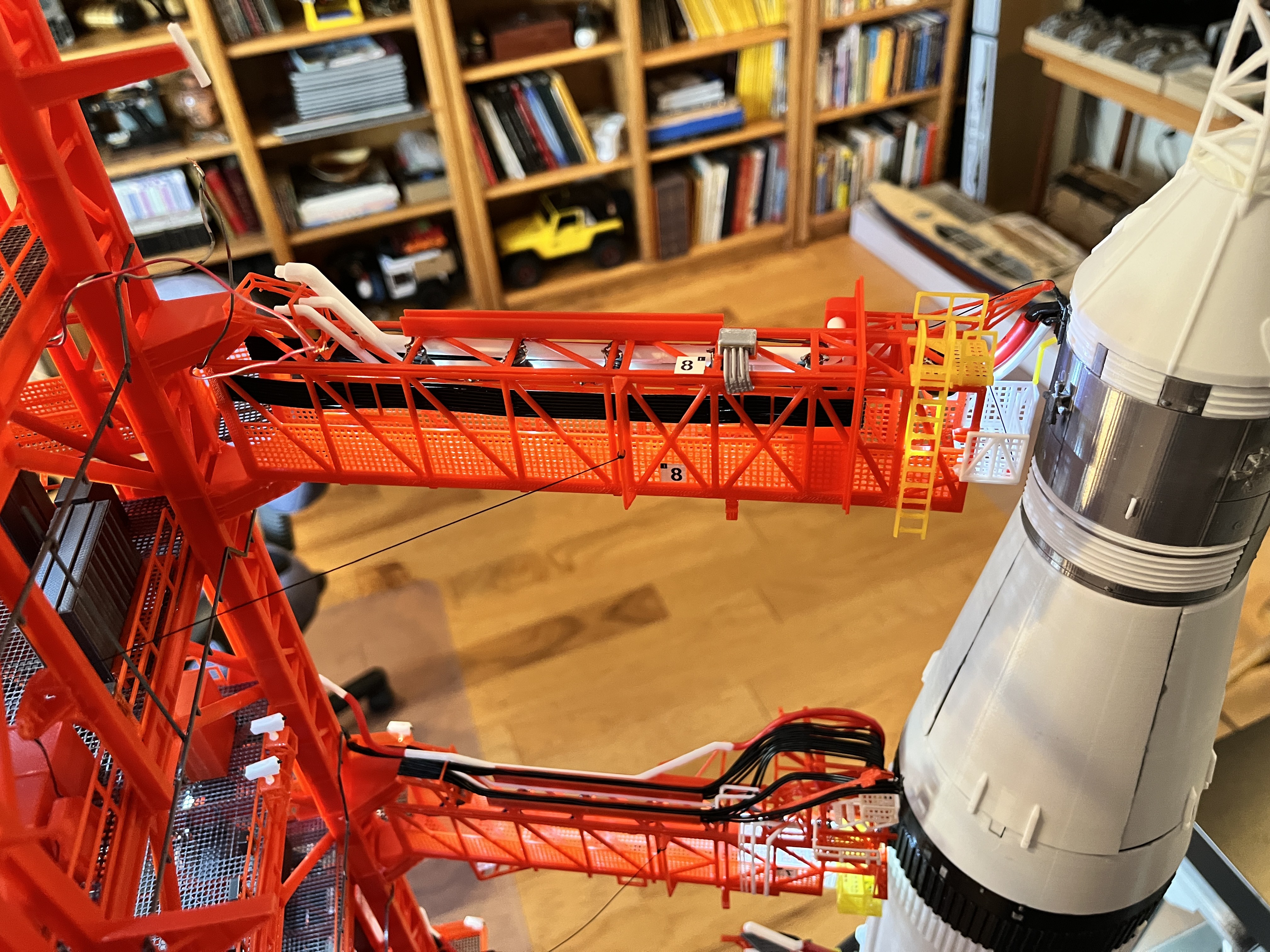
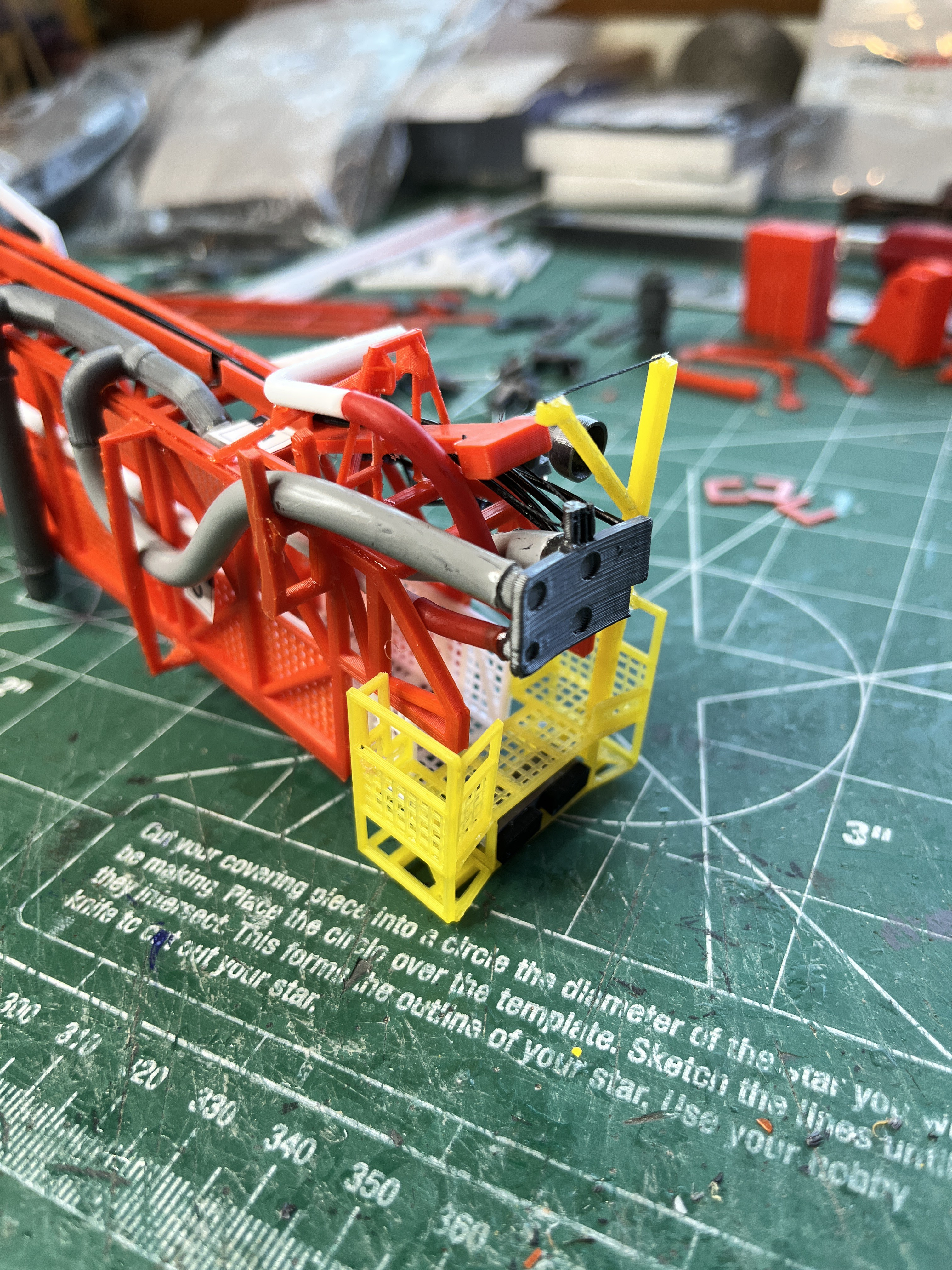
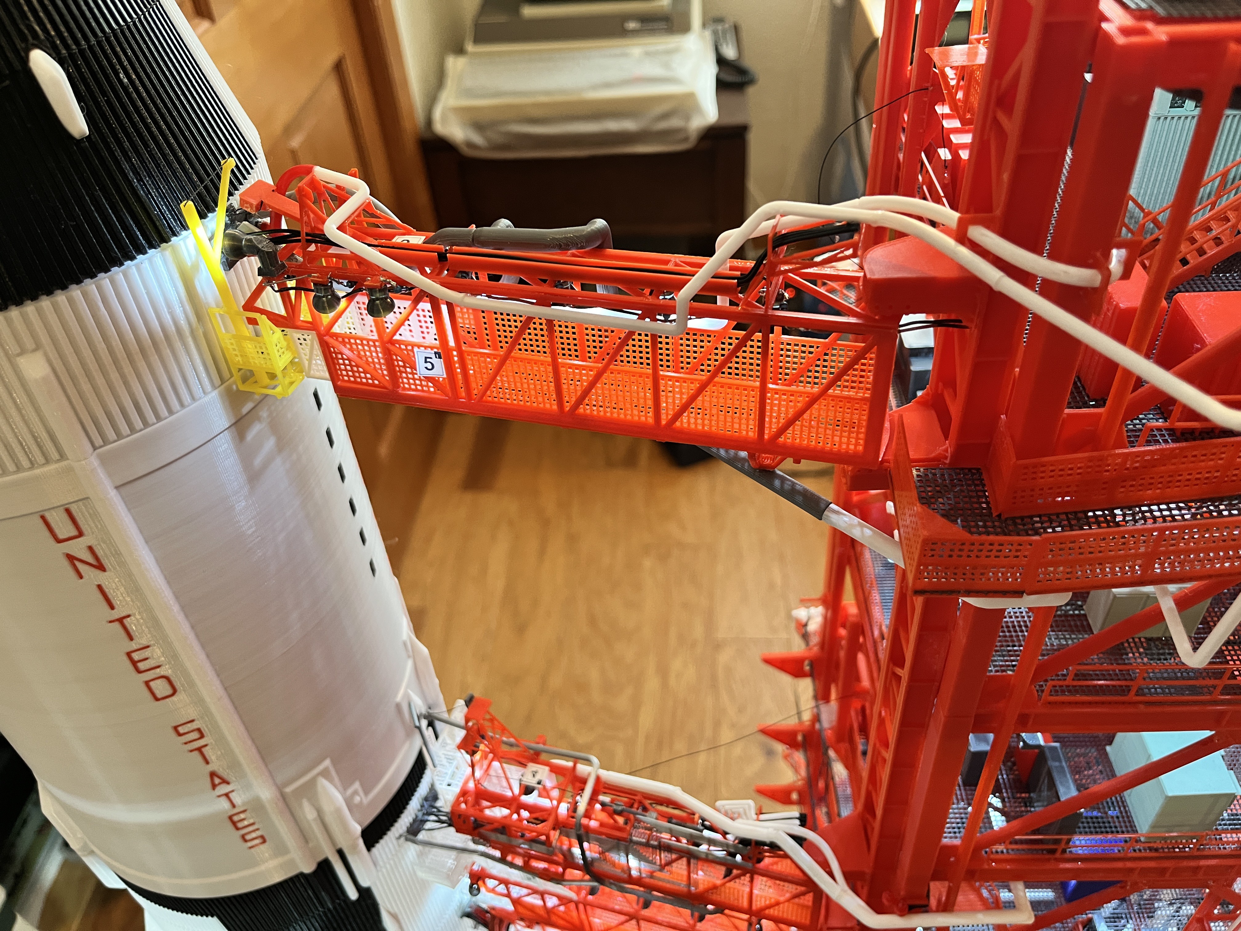
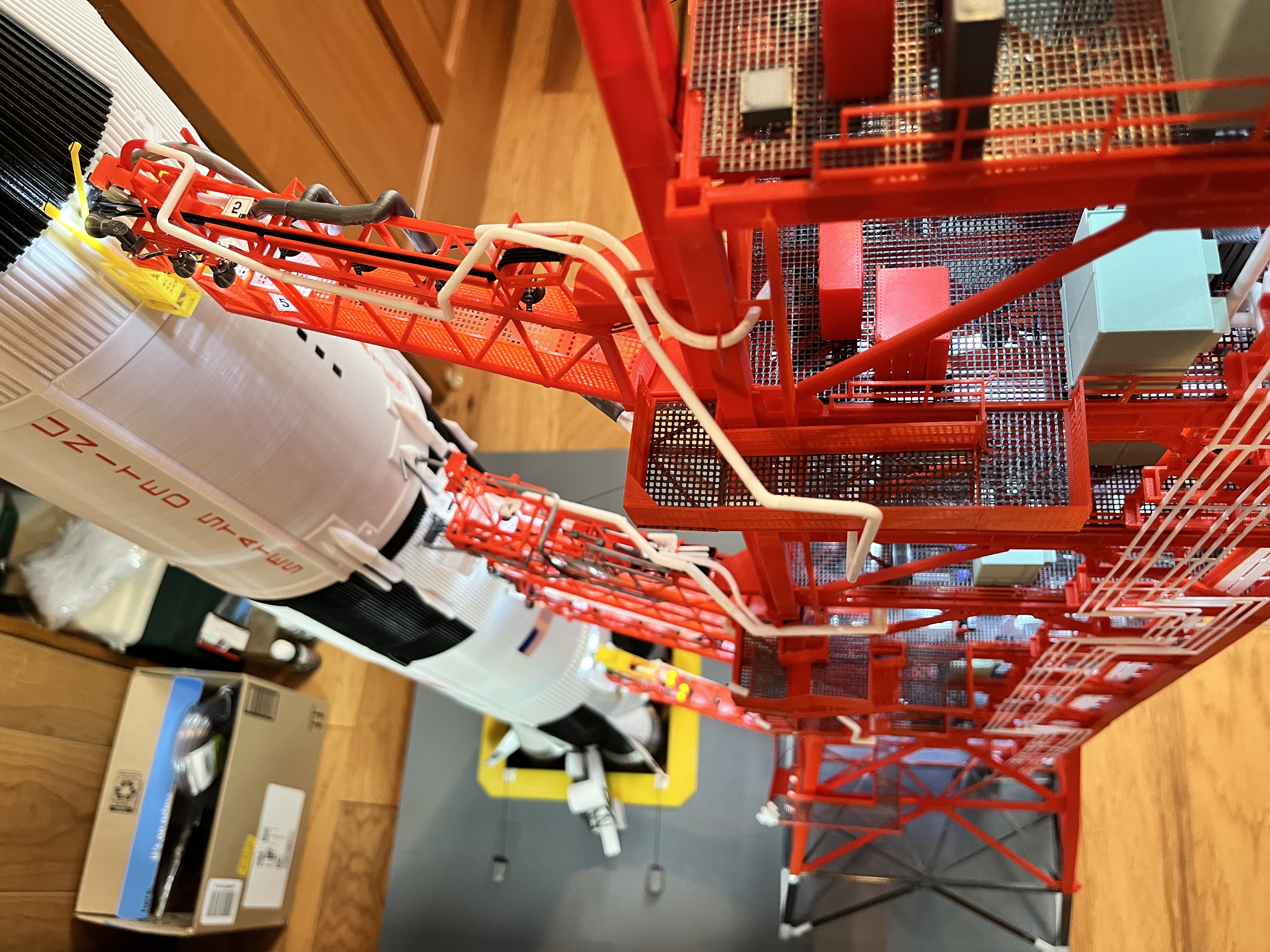
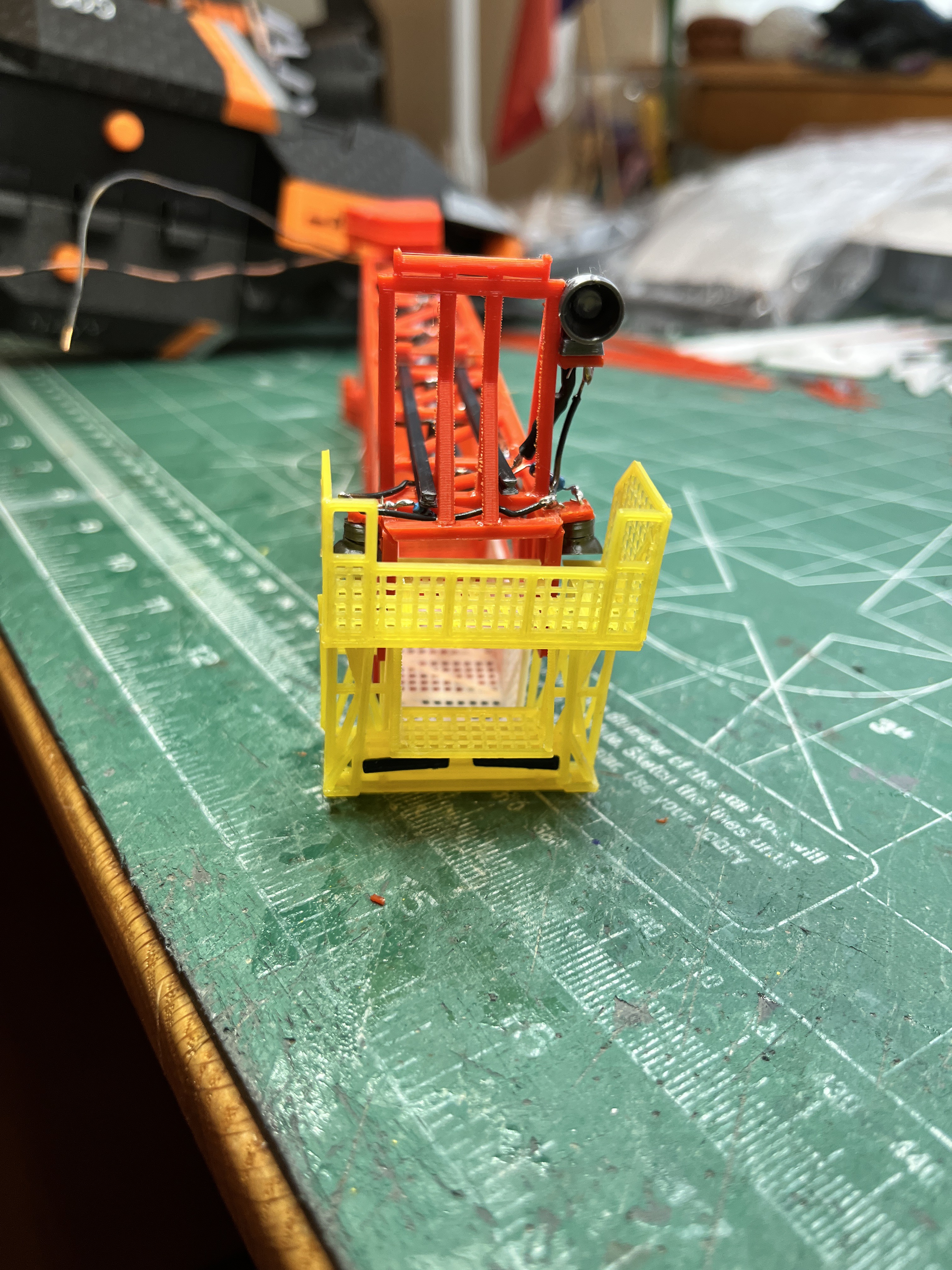
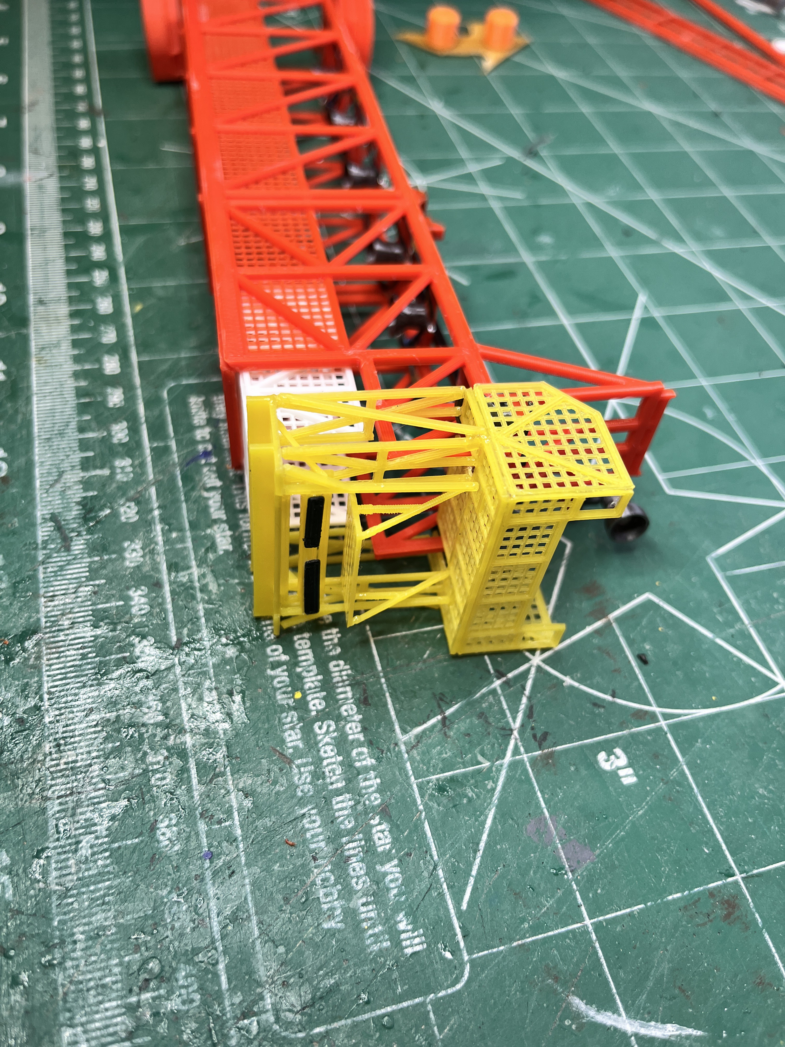
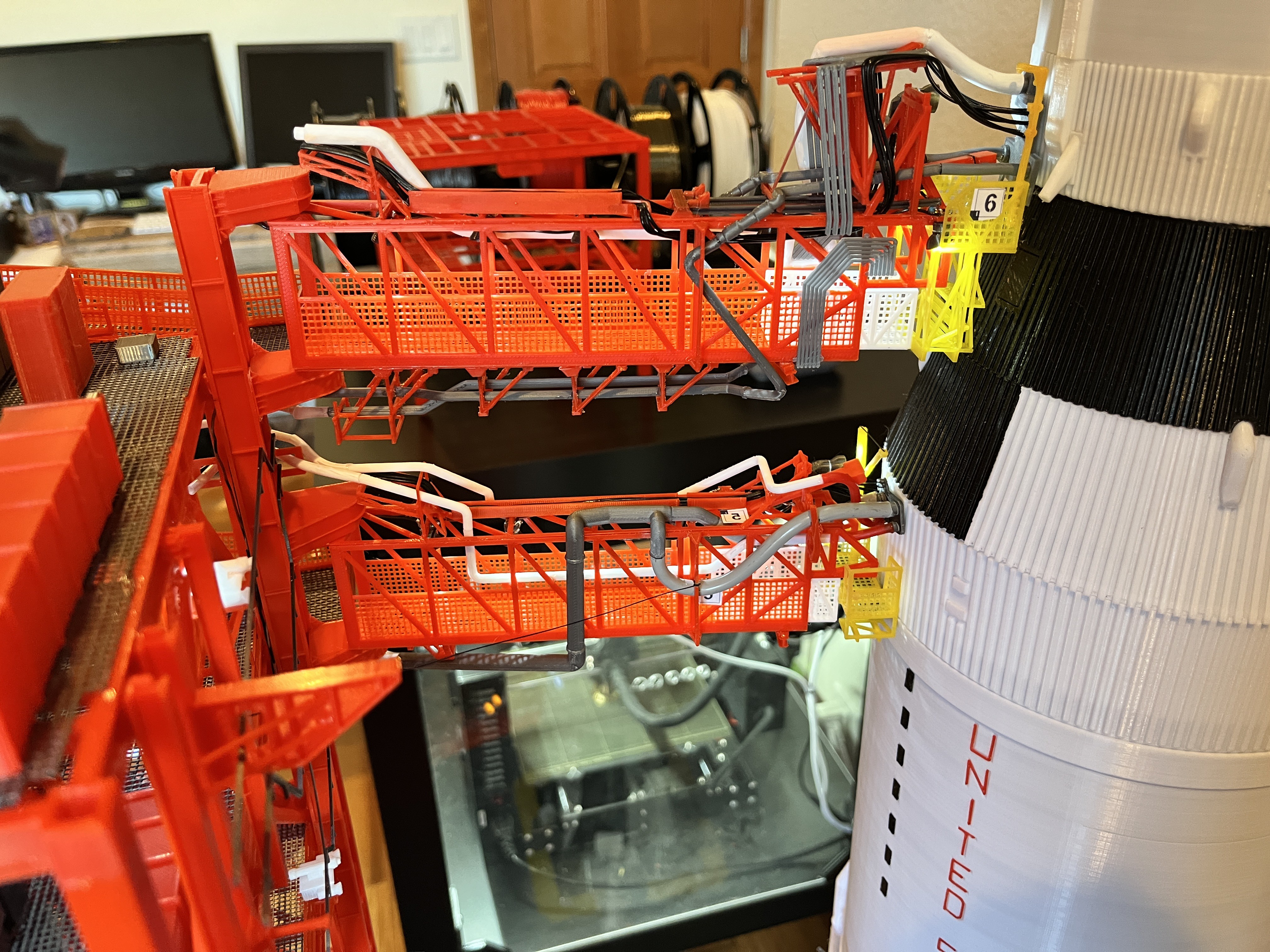
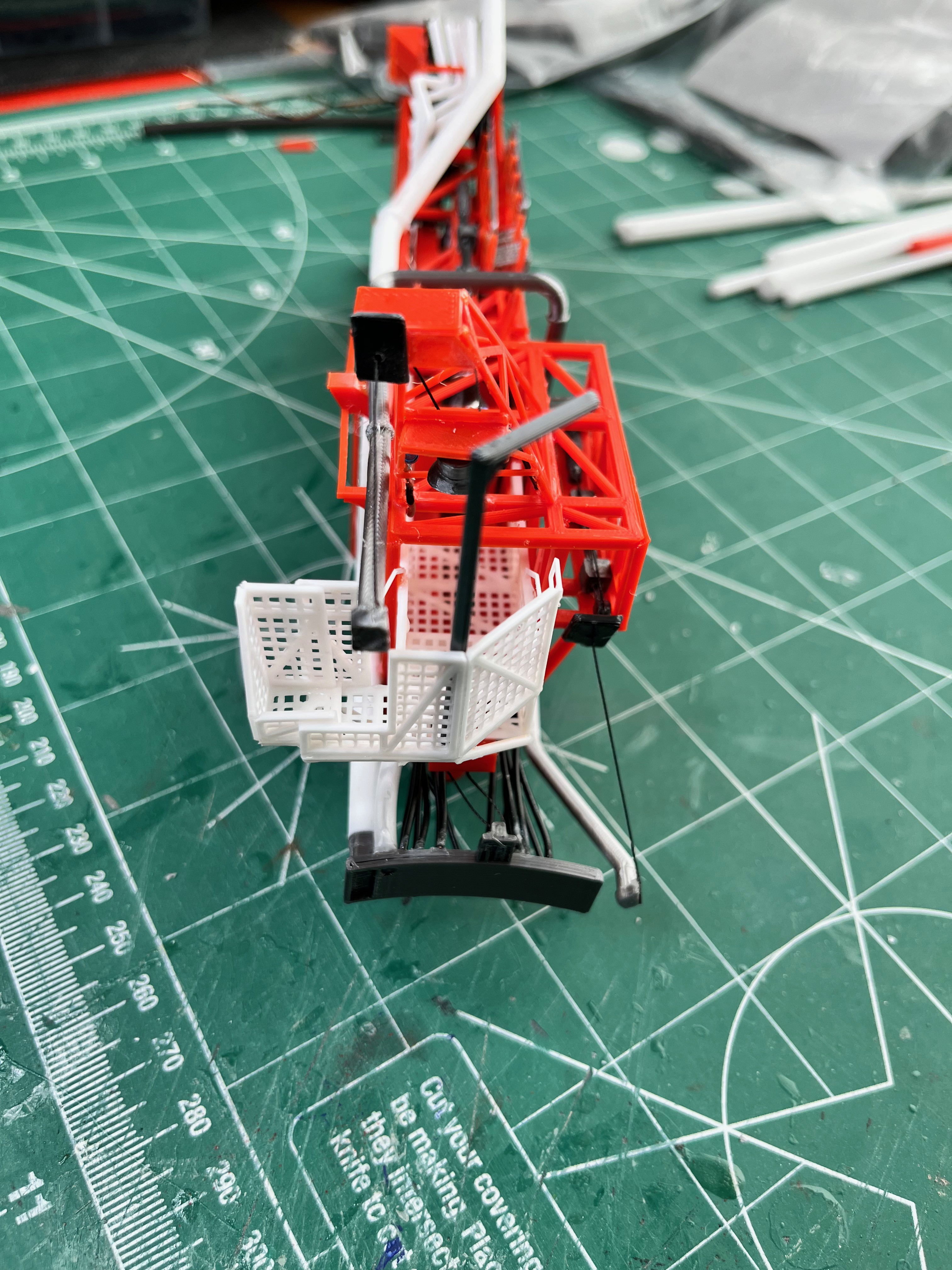
- Swing Arm Common - Complete
- Swing Arm #1 - Complete
- Swing Arm #2 - Complete
- Swing Arm #3 - Complete
- Swing Arm #4 - Complete
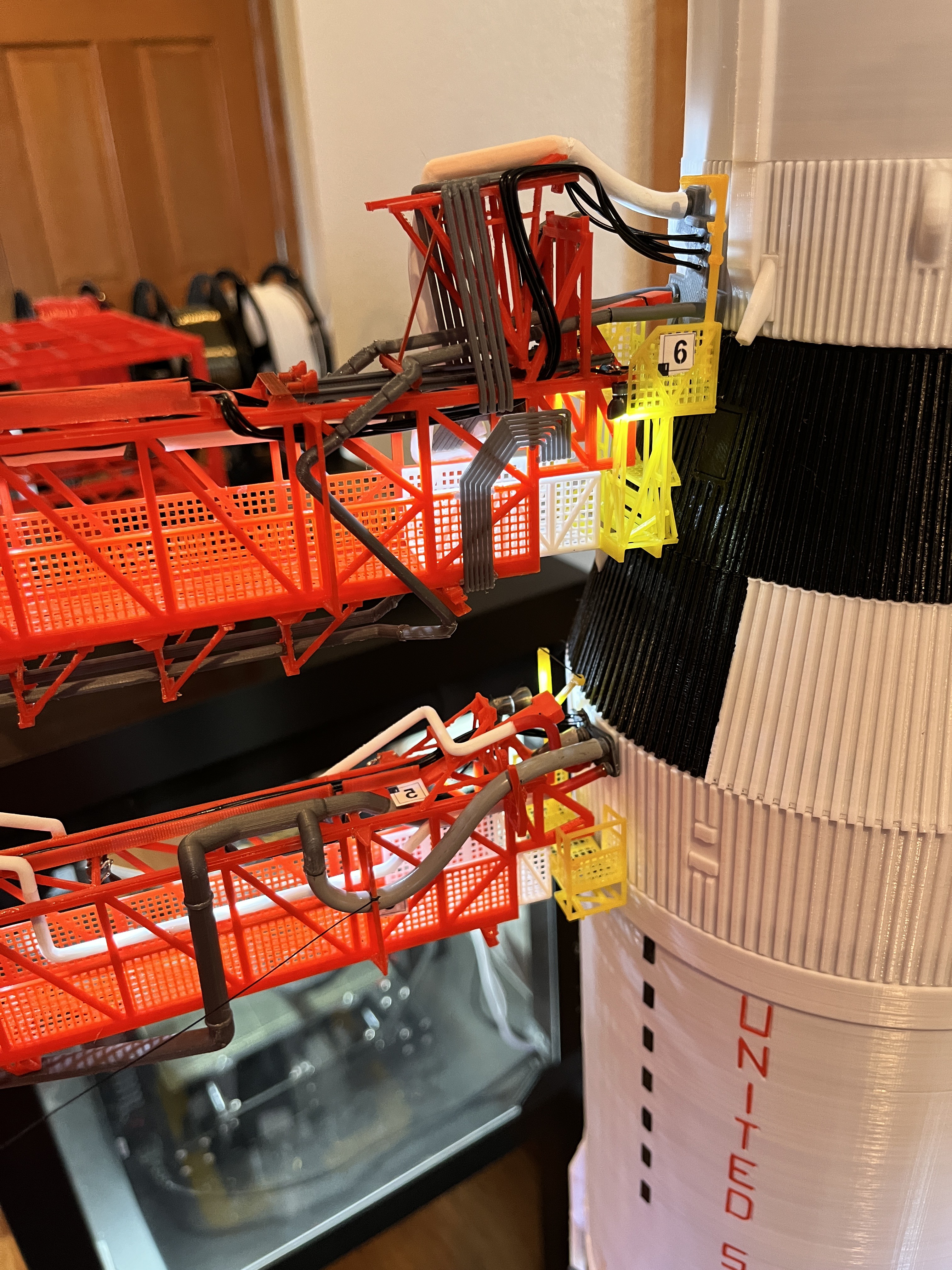
- Swing Arm #5 - Complete
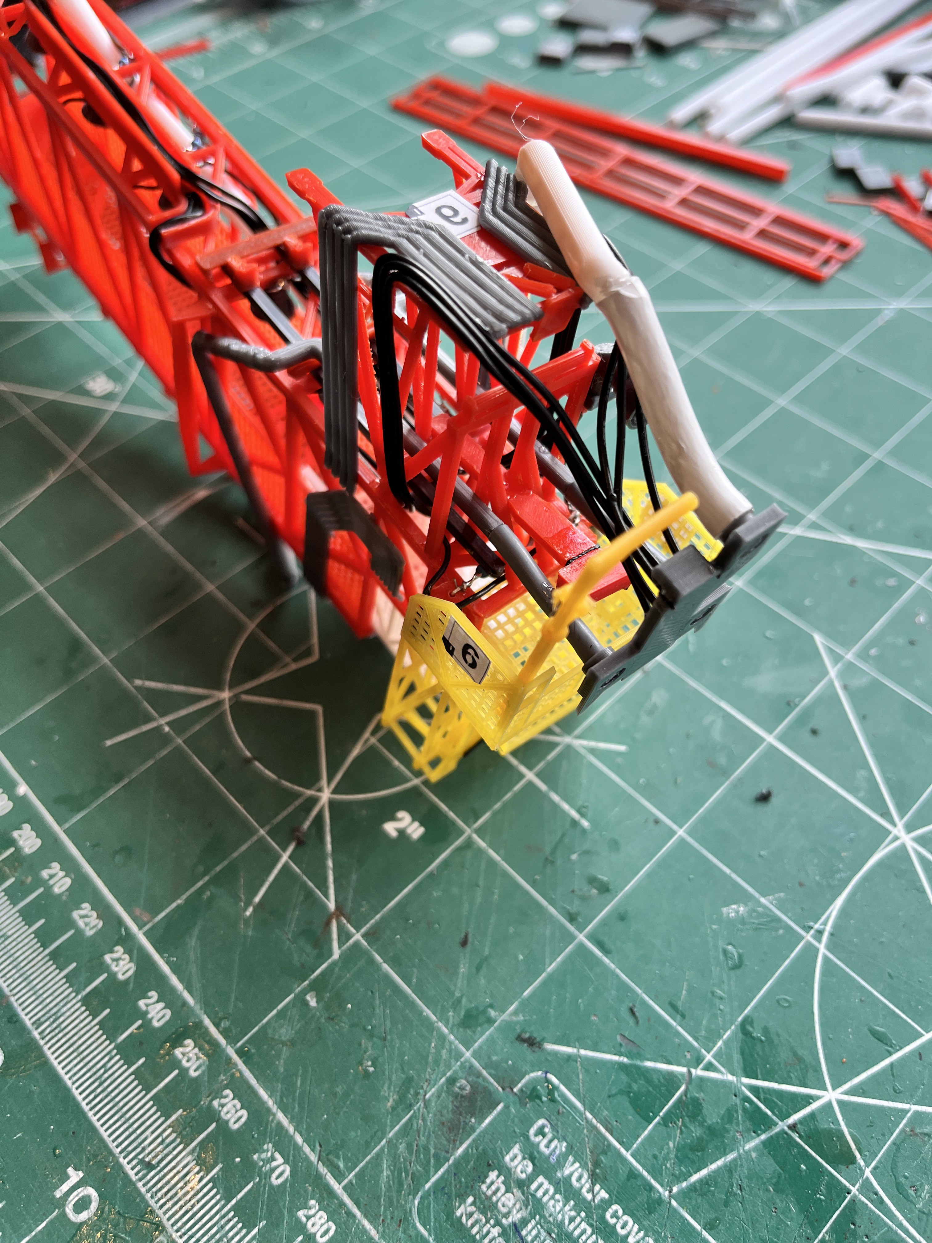
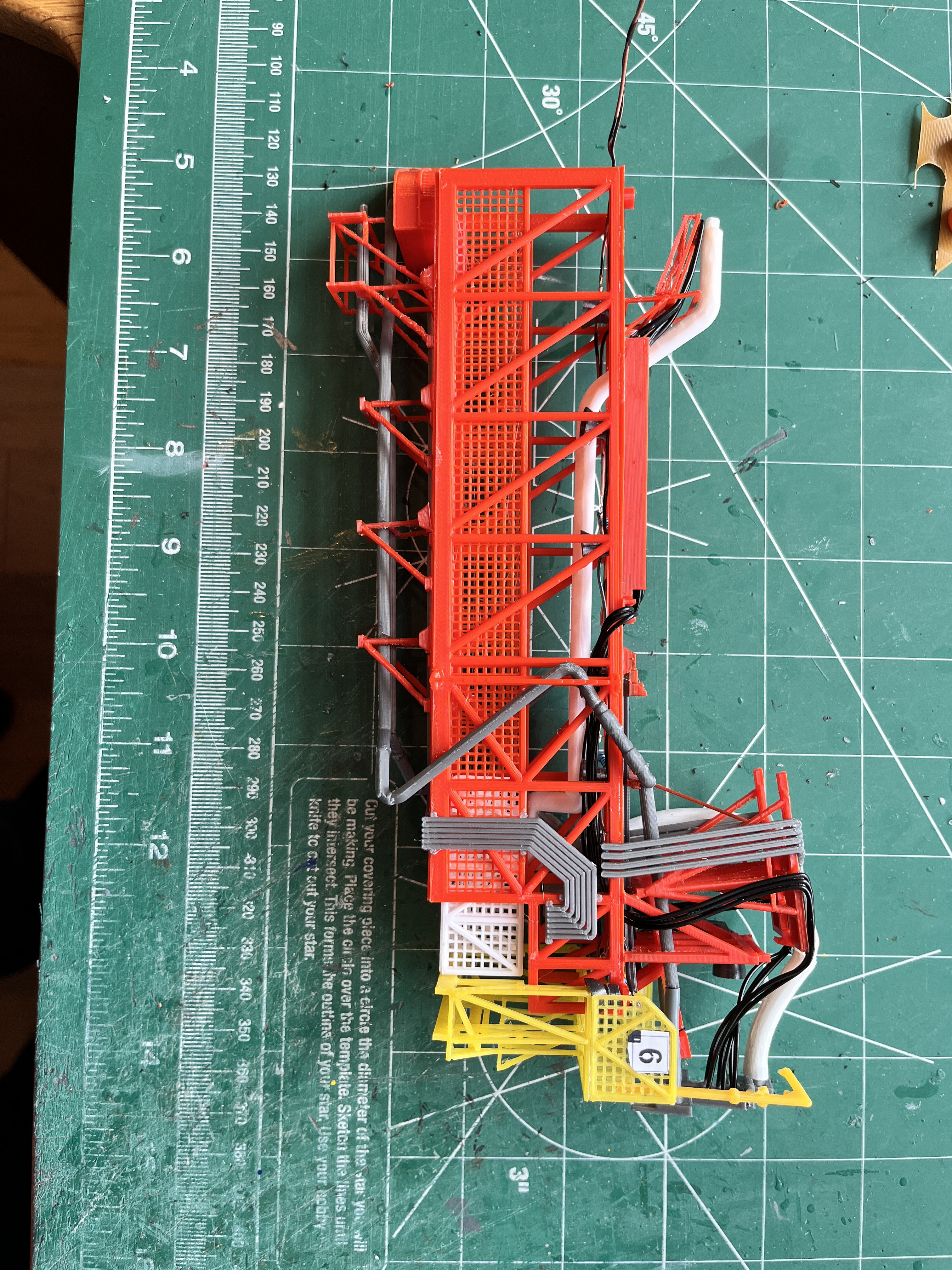
- Swing Arm #6 - Complete
- Swing Arm #7 - Complete
- Swing Arm #8 - Complete
- Swing Arm #9 - Complete
- DRRS - Complete
- Crane - Complete
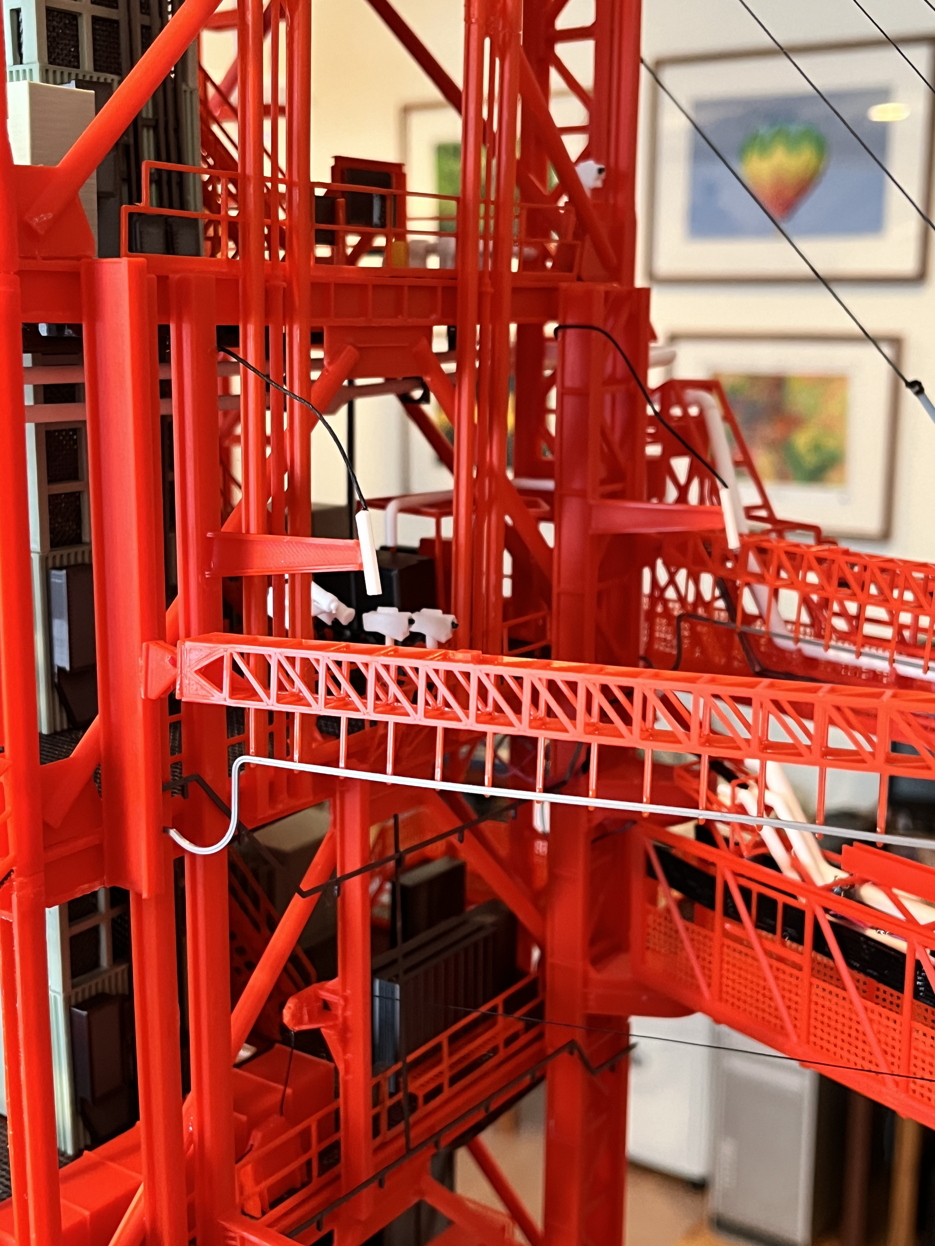
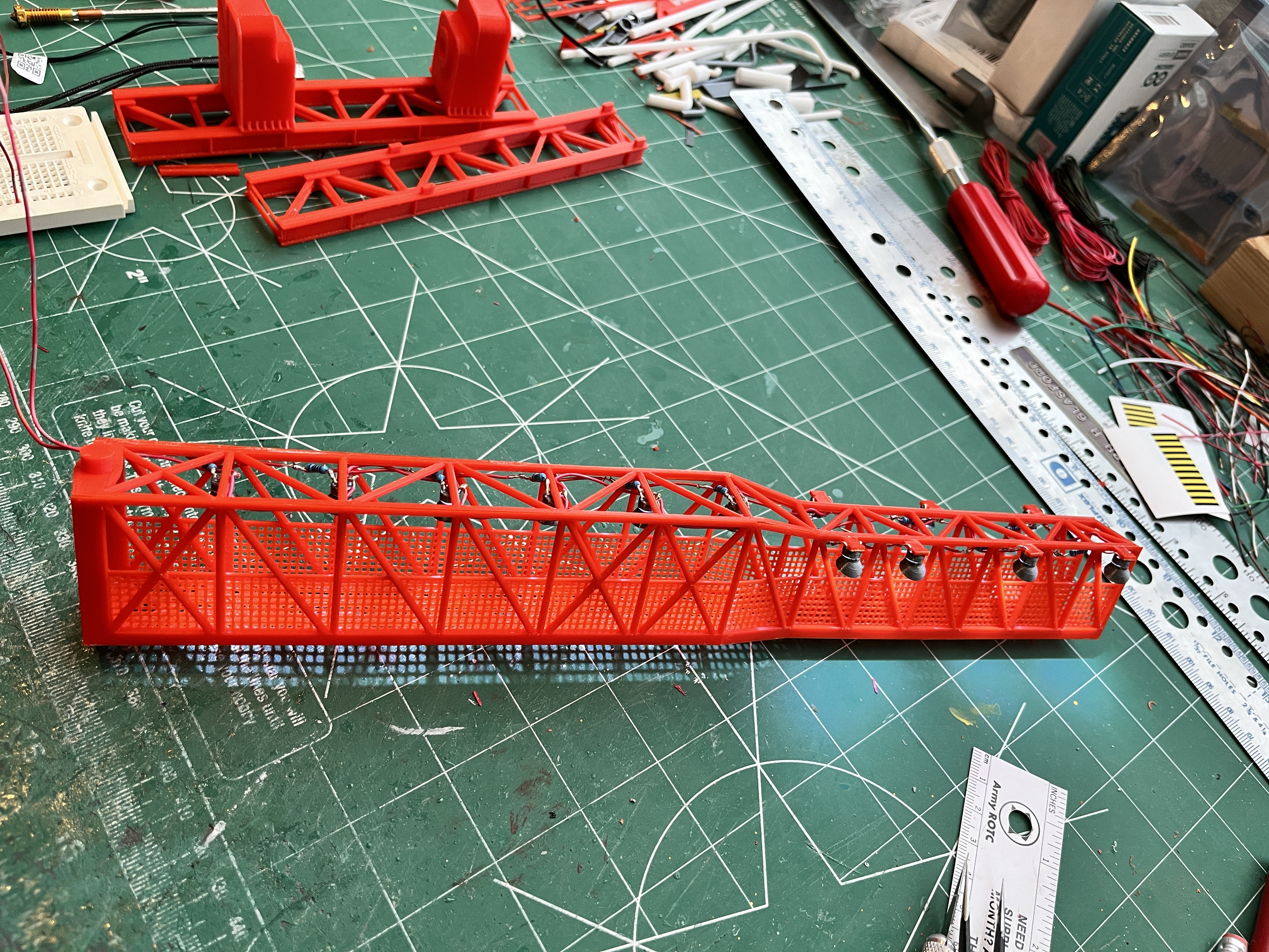
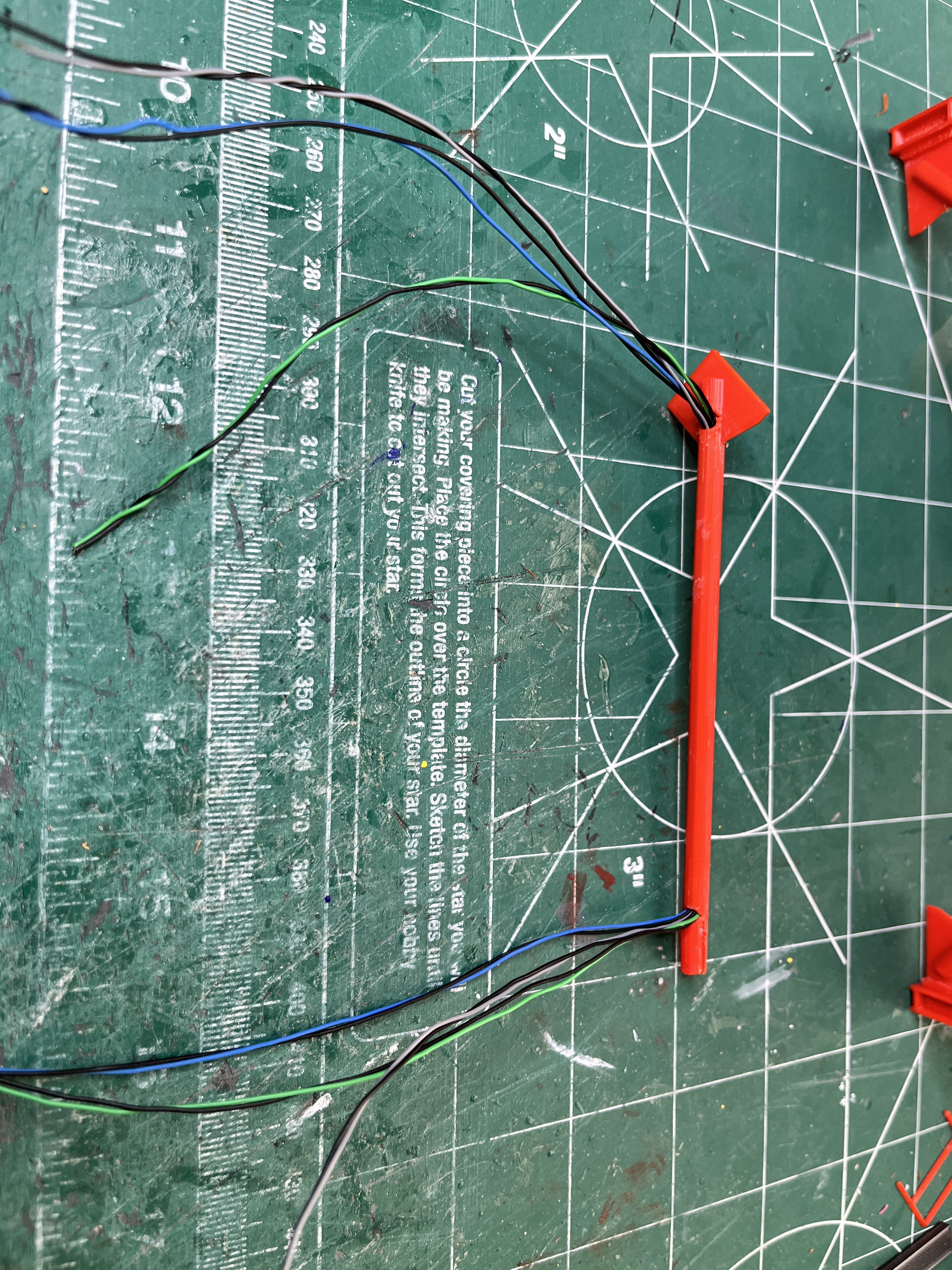
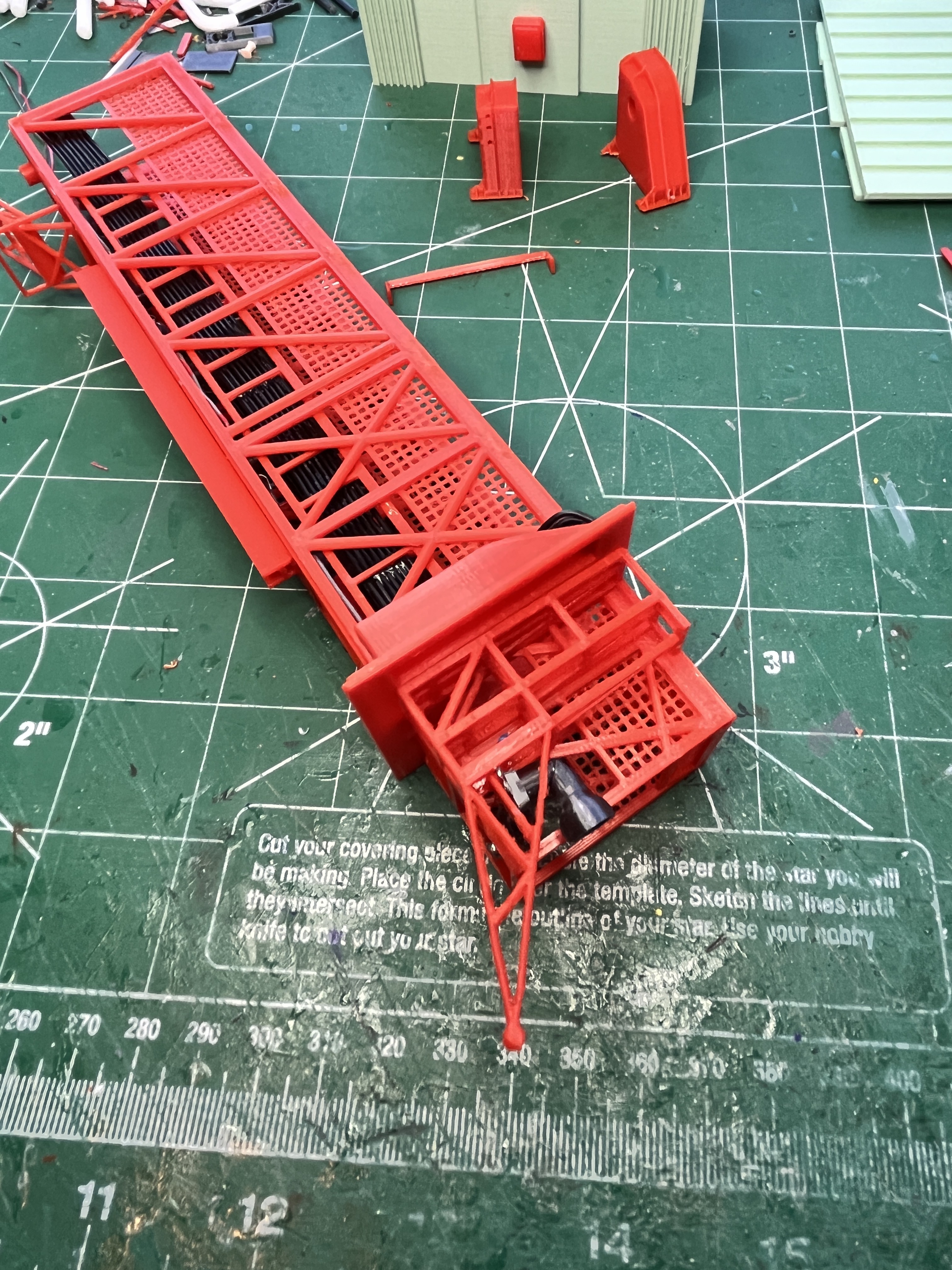
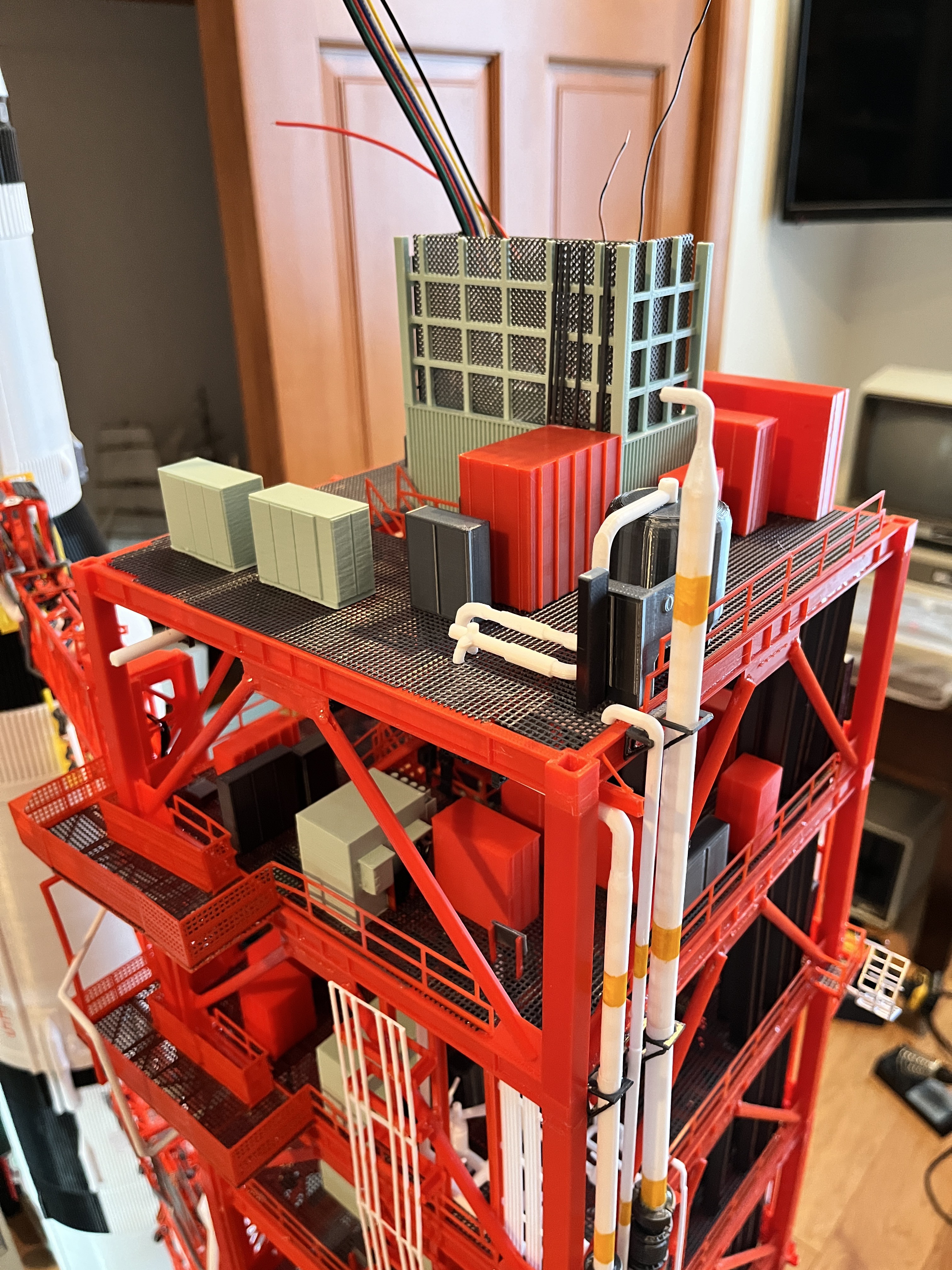
I would highly recommend lighting the model. The lights are not too hard to make and really add to the look of the model by lighting the dark interior of the levels, even in the daytime.


 Roger Cobra
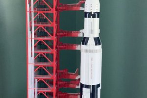
 Mark Howe
 Jordan Réjaud
You are welcome. i have been working on this for over 2 years. Fortunately there is a LUT Group that is providing me with all the original NASA technical documents and pictures.