 Jac Goudsmit
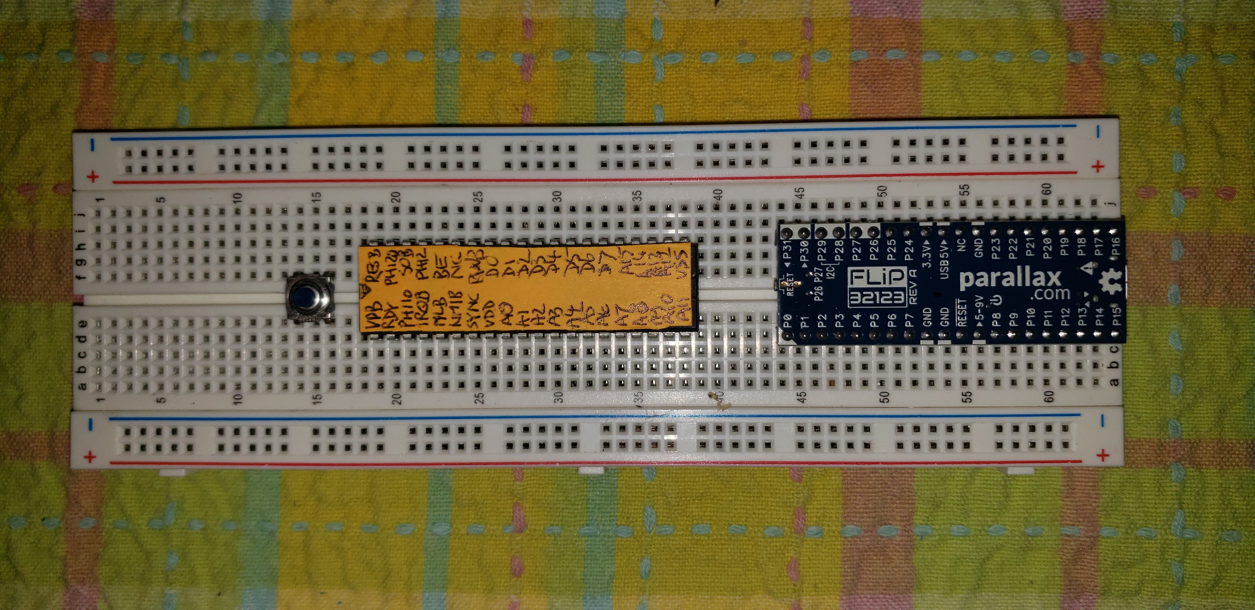
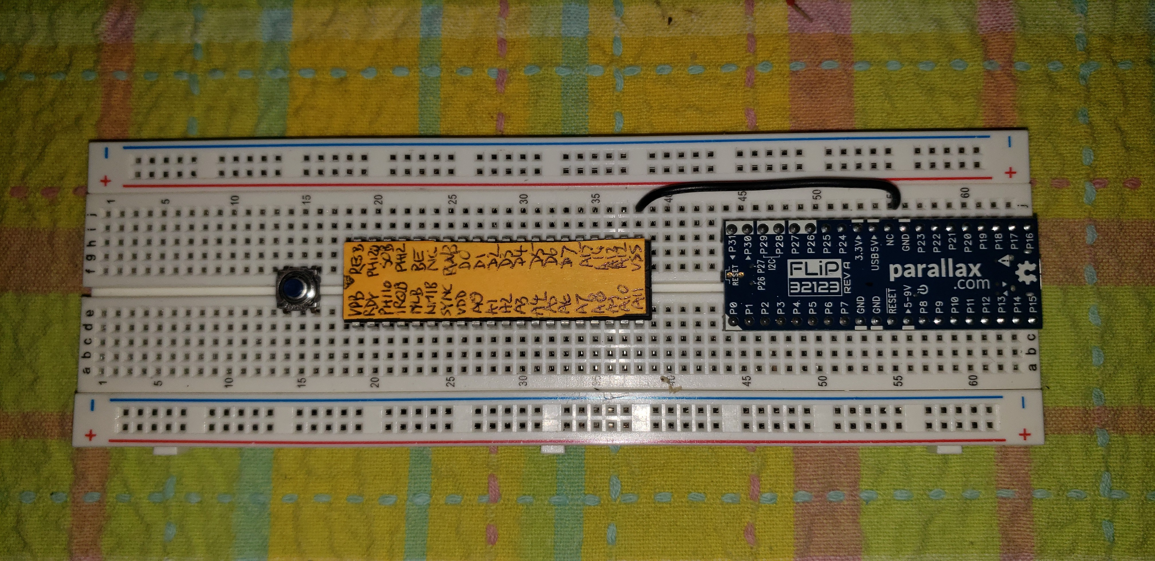
The L-Star project is an open-source single-board computer design that uses a Propeller microcontroller to control a 65C02 processor. You can use it to emulate early 6502-based computers such as the Apple-1 or the OSI Challenger, or you can invent your own 6502 computer.
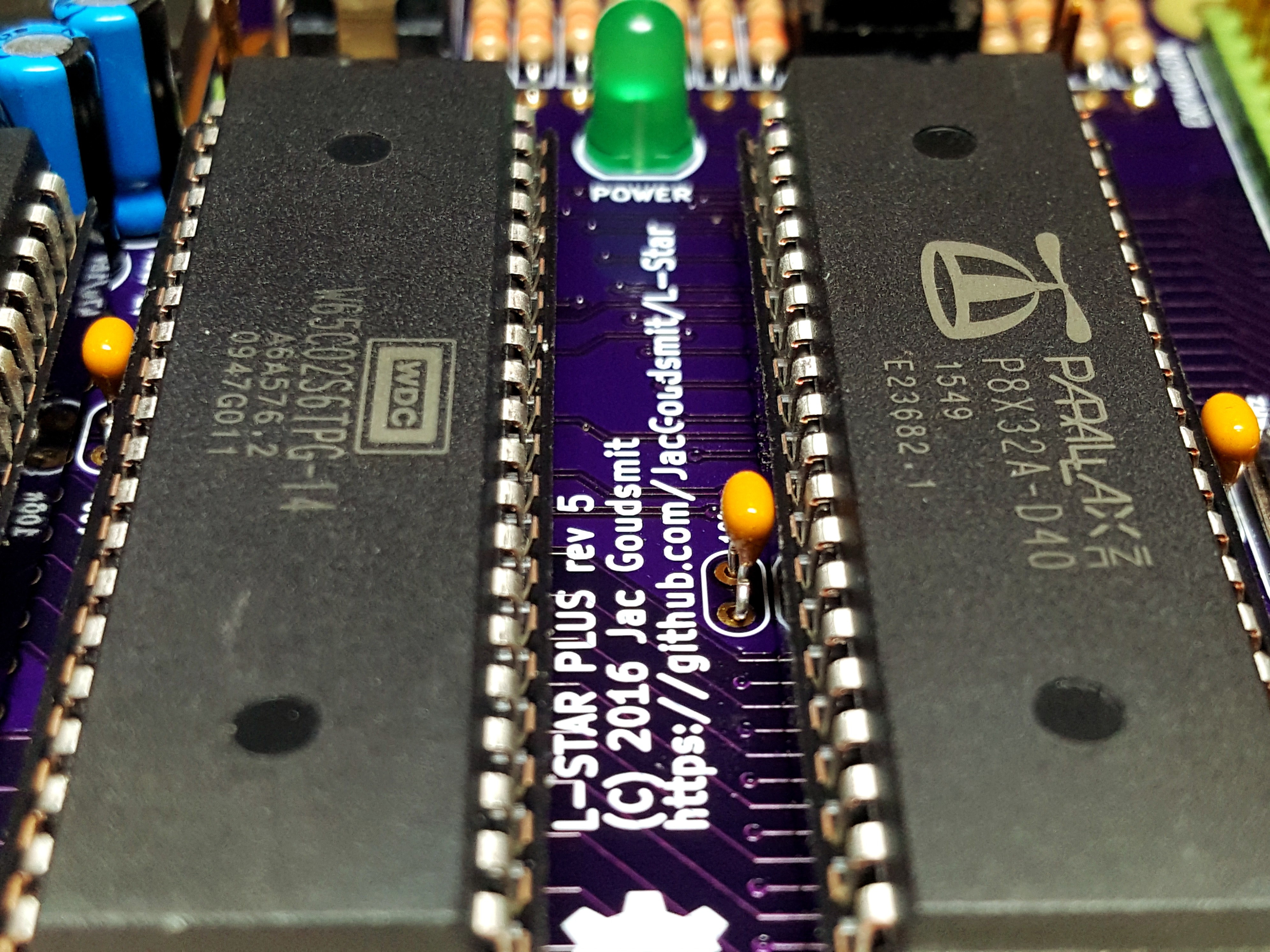
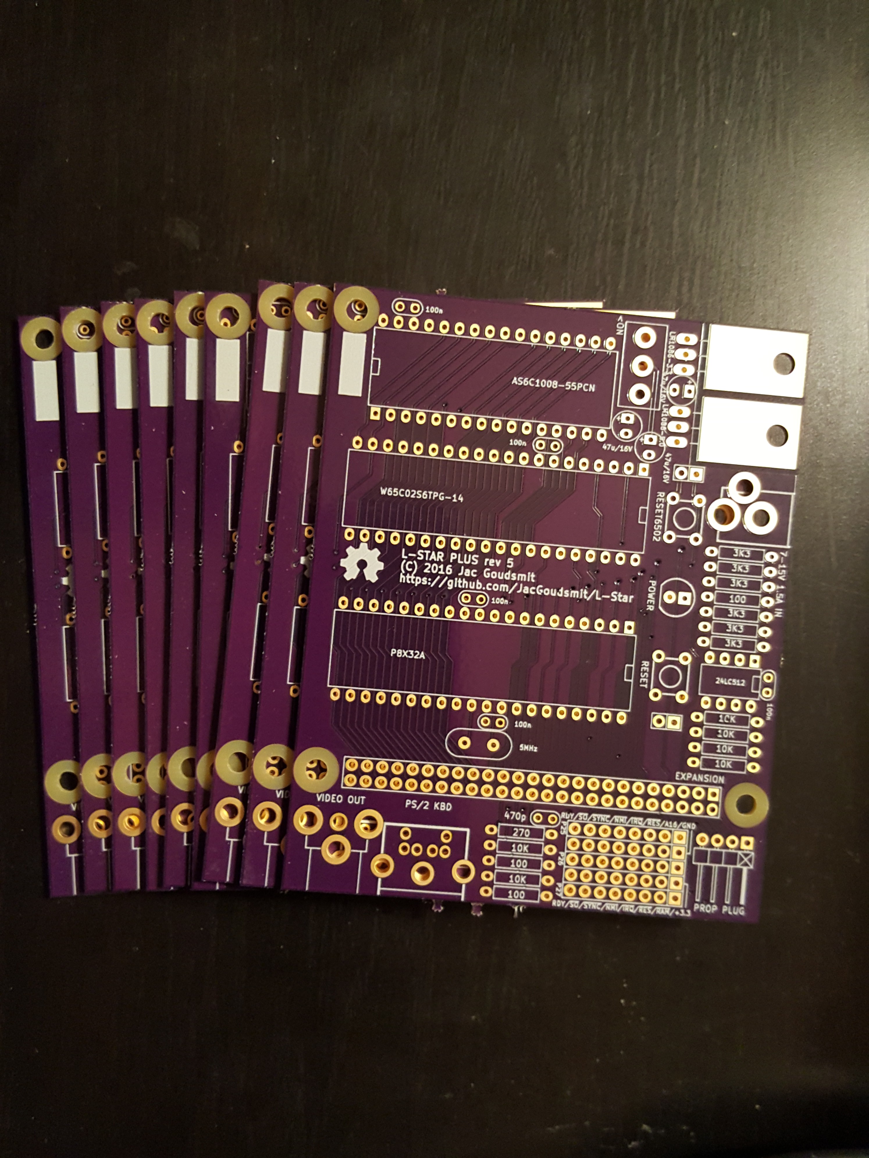
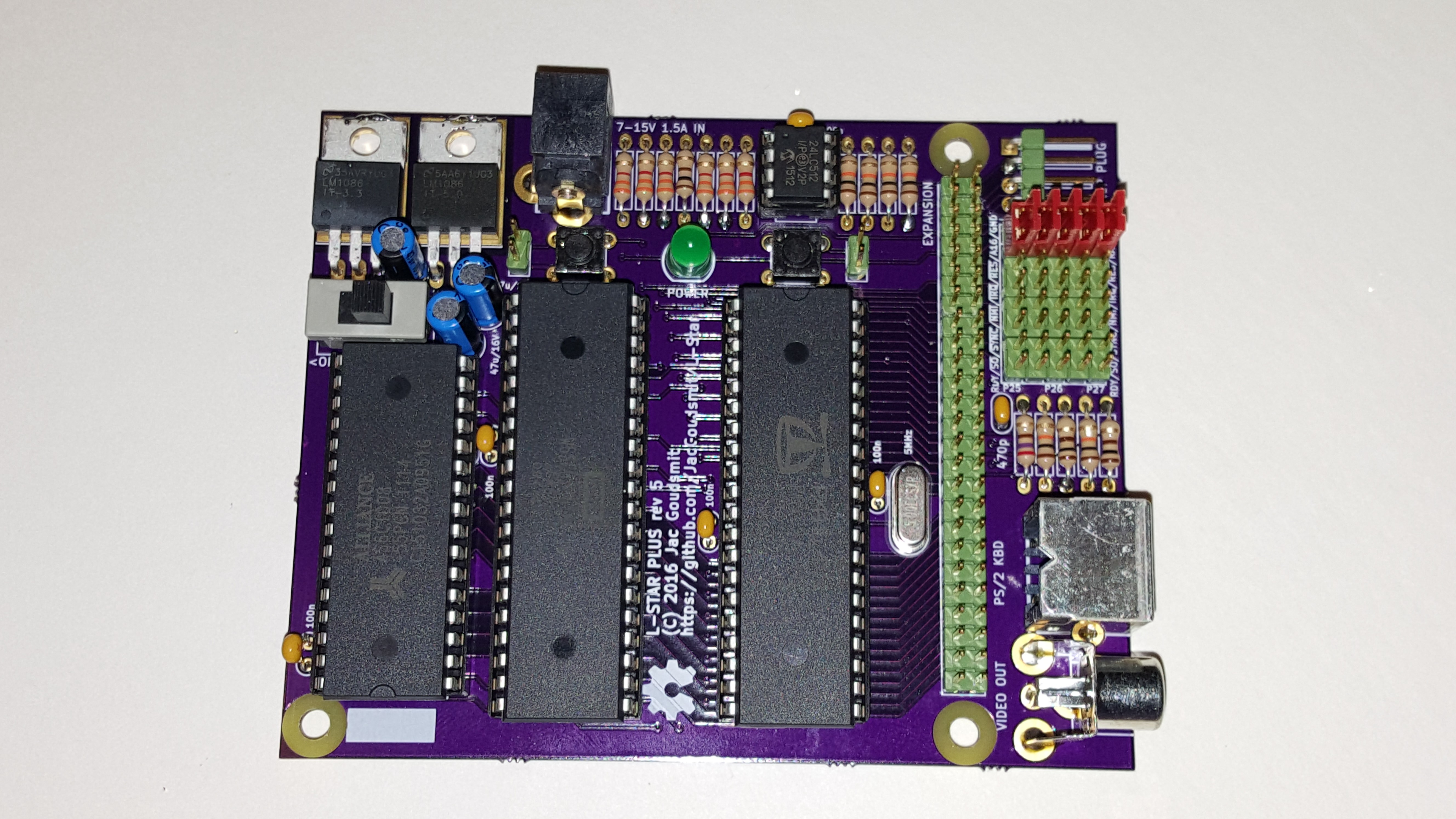
All the parts that are needed to put an L-Star together are available in through-hole packages, so you can build it on a breadboard, or on a Propeller proto board. Or you can order a kit on Tindie (click on the Tindie link on the project page), which has some extra features such as a 128KB static RAM chip and an expansion port.


 If you've followed me long enough, you know that my original purpose for the
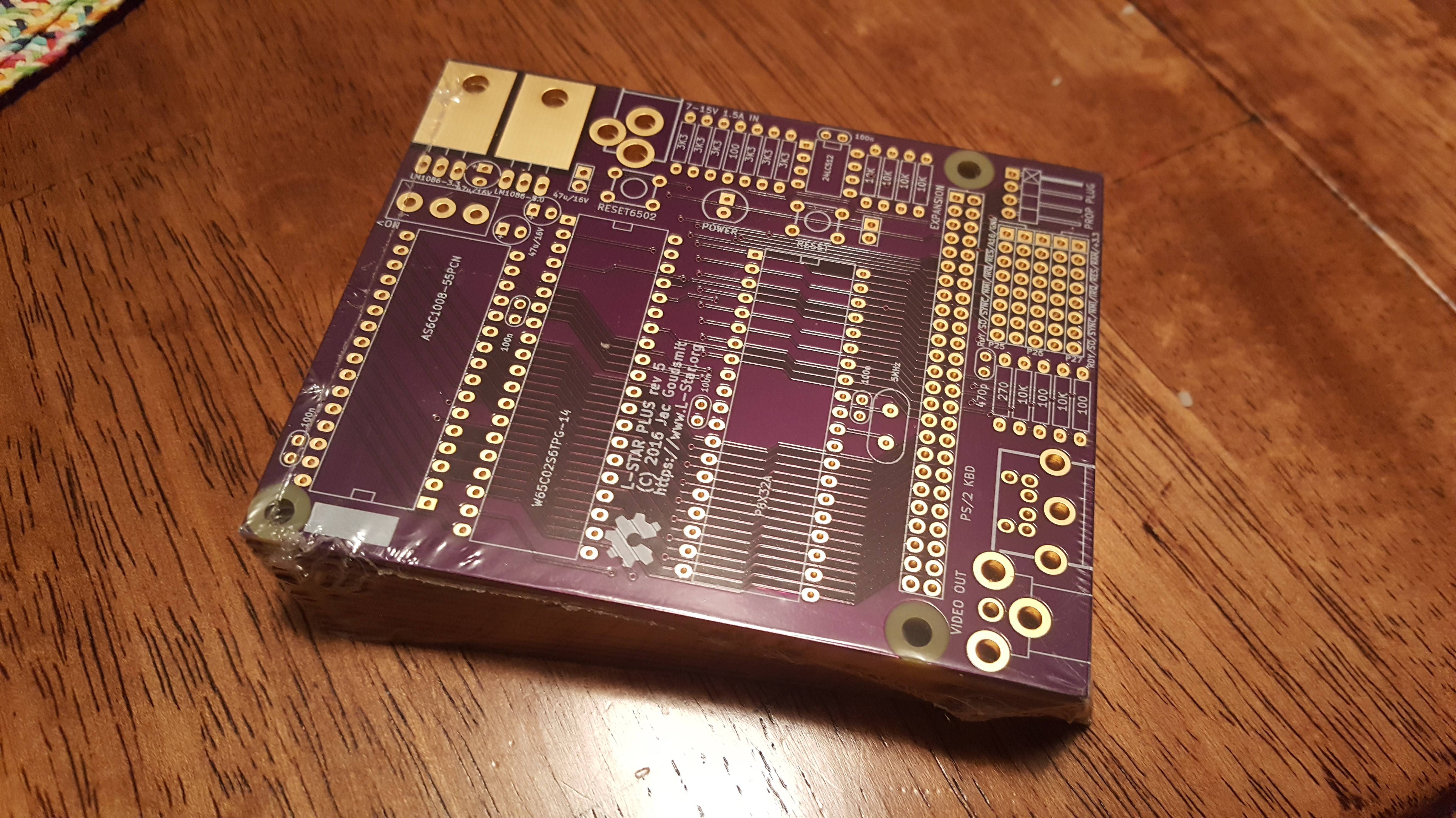

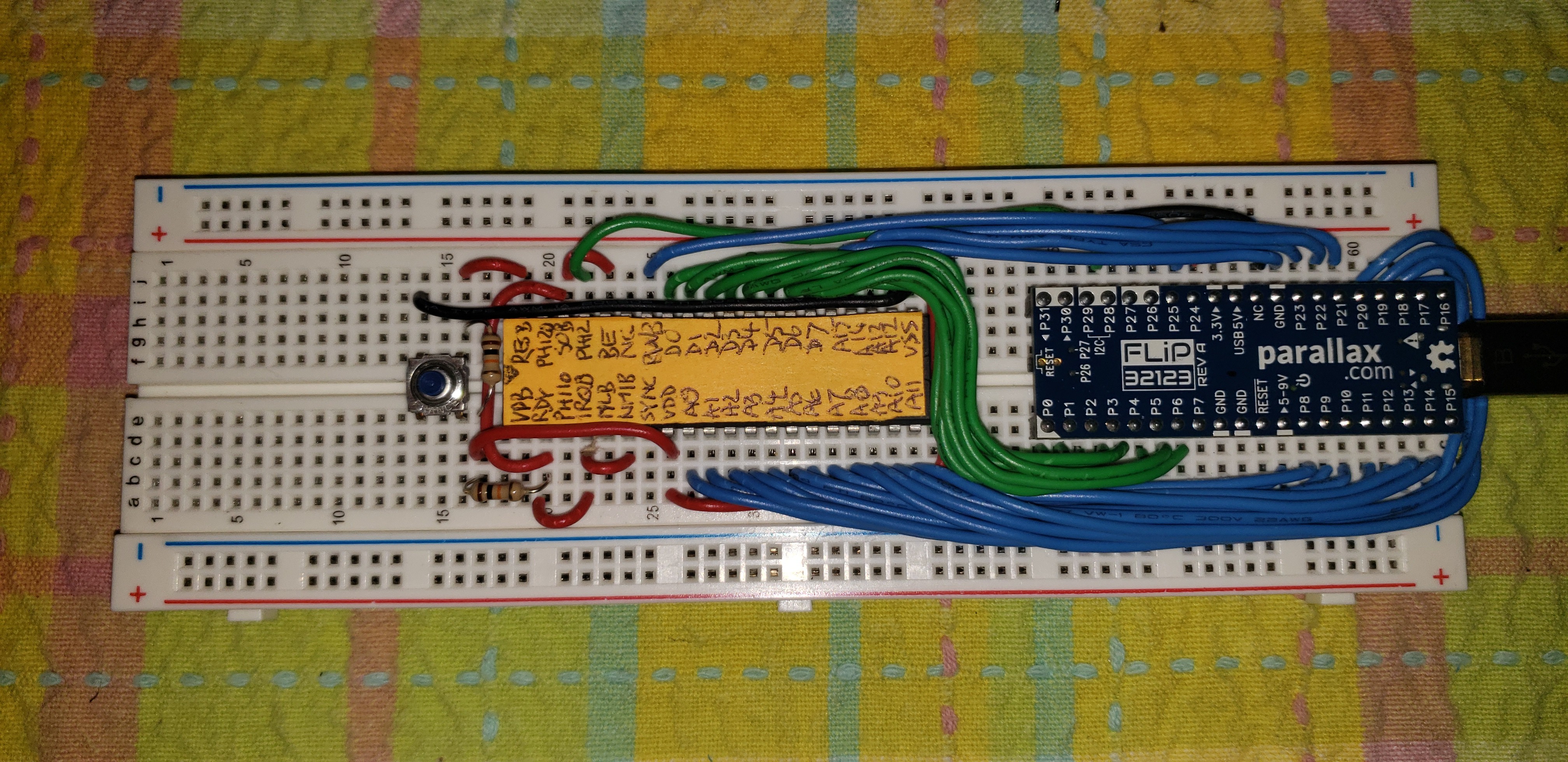 The Propeller microcontroller that I used for the L-Star project, needs quite a bit of peripheral hardware to make it useful. Parallax, the company that makes the Propeller, recognized this and they make the Propeller FLiP module available (their item number is 32123). The FLiP is more expensive than the Propeller of course, but it not only has the Propeller on board and gives you access to all I/O pins, but it also has an EEPROM, an FTDI chip for USB communication with a computer, a few LEDs for debugging, and a power supply that can use either the USB connection or an external power source as input, and generates 3.3V as well as 5V as output. The photo below shows two FLiP modules: one from the top and one from the bottom.
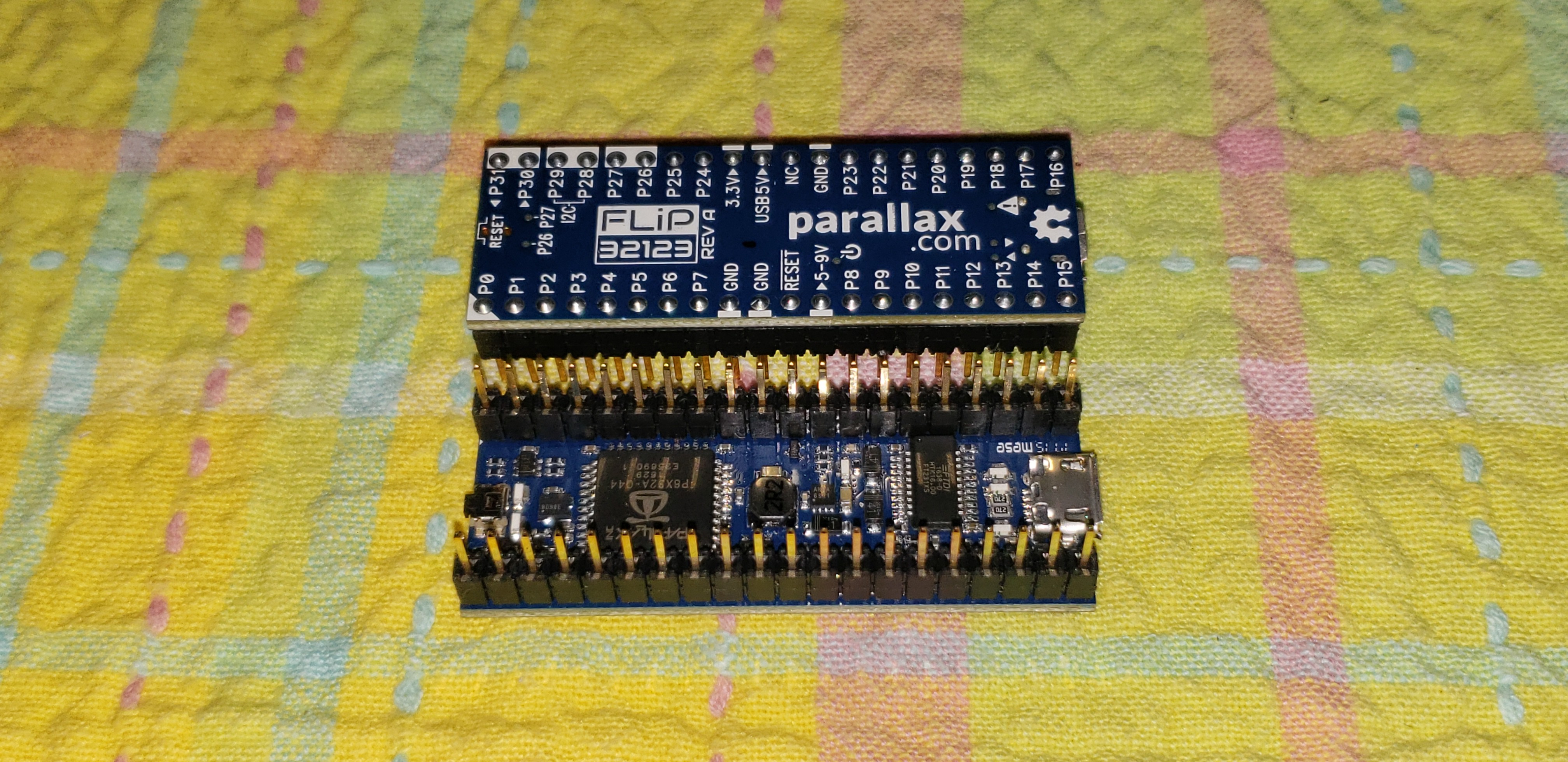


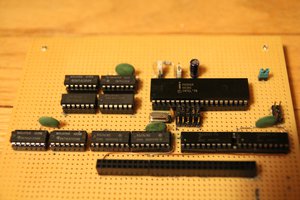
 Bentendo64
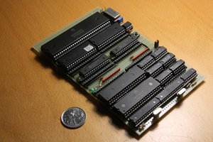
 Hayden Kroepfl
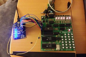
 Christian Bjelle
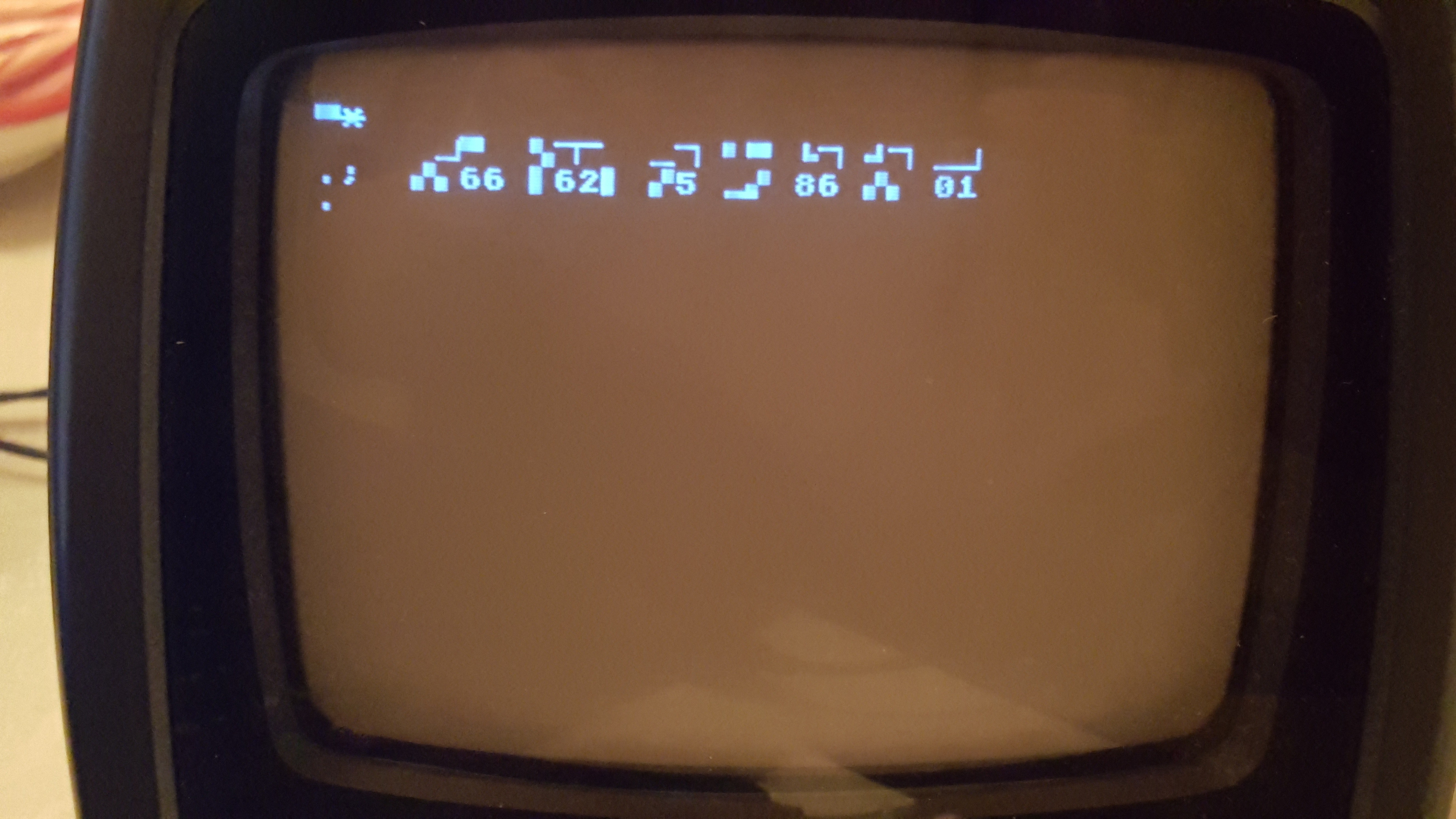
OSI emulation: in APR 2017 post indicated would be adding use of serial port to PC. Still planning to do so? :-)